
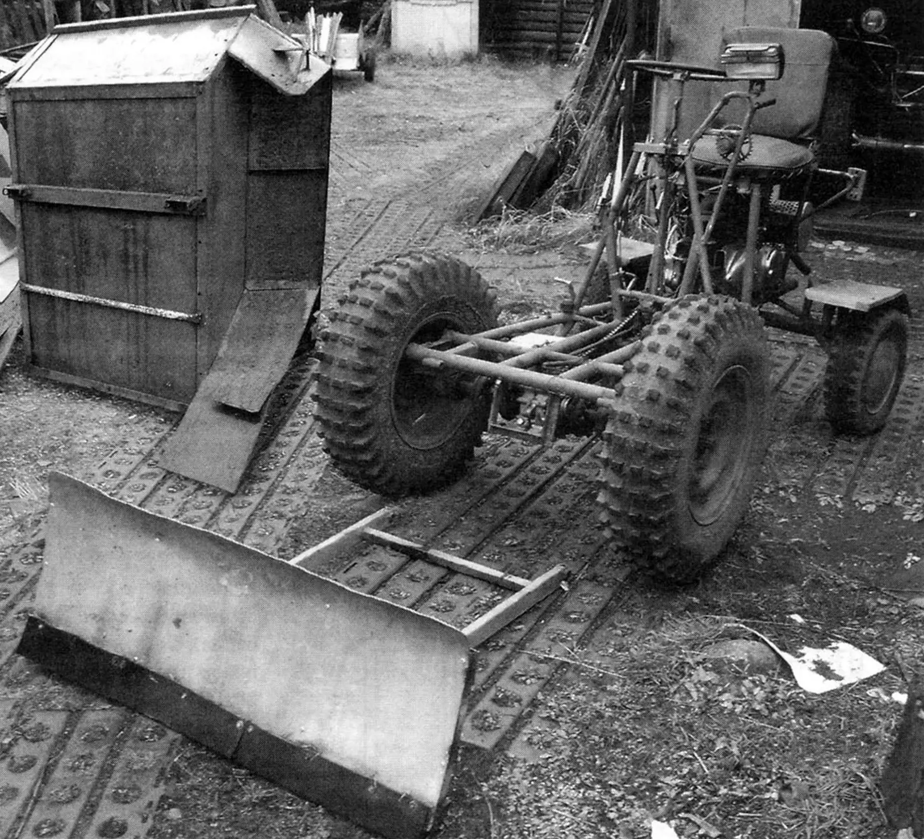
I am a long-time reader and regular subscriber to the magazine “Modelist-Konstruktor”. Over almost forty years, I have not only familiarized myself with machines and mechanisms of amateur designers, but also created my own. Therefore, I can count myself among the cohort of experienced “DIYers”. I mainly built agricultural and transport equipment (from walk-behind tractors to jeeps). Some of what I created earlier I disassembled or remade, some I sold, and some I still use, for example, a mini-tractor (or rather, a self-propelled chassis), the design of which I present to the readers.
The chassis is designed for transporting various loads for homestead use (both in its own body and in a towed trailer), and in winter — also for snow removal using a front-mounted bulldozer blade.
I will begin the description of the construction with the frame. It is welded mainly from steel water pipes of circular cross-section. In plan (top view), the frame has the shape of an elongated trapezoid with a large base at the front.

1 — front drive wheel (from UAZ vehicle with modified “checkerboard” tires, 2 pcs.); 2 — wheel hub (from UAZ vehicle); 3 — body sheathing (steel sheet 1 mm); 4 — white reflector (2 pcs.); 5 — yellow reflector (2 pcs.); 6 — body frame (angle No. 2.5 and No. 3); 7 — instrument panel; 8 — headlight (from tractor); 9 — steering wheel; 10 — intermediate chain reducer; 11 — intermediate shaft chain drive housing (steel sheet 1 mm); 12 — air filter; 13 — tool box; 14 — seat; 15 — ignition coil; 16 — carburetor; 17 — seat back; 18 — fuel tank; 19 — engine (from Izh-Planeta-3 motorcycle); 20 — muffler (from Buran snowmobile); 21 — rear wheel fender (steel sheet 1 mm, 2 pcs.); 22 — rear steerable wheel (from SZD motorized wheelchair, 2 pcs.); 23 — longitudinal steering rod; 24 — chains; 25 — steering mechanism (from SZD motorized wheelchair); 26 — frame; 27 — front wheel splash guard (rubber 5 mm, 2 pcs.); 28 — main drive — reverse reducer (from Ant cargo scooter); 29 — half-shaft (cardan joints from motorized wheelchair, 2 pcs.); 30 — red reflector (2 pcs.); 31 — front fender (steel sheet 1 mm, 2 pcs.); 32 — rear lamp (purchased item); 33 — rear axle; 34 — steering knuckle posts (channel No. 5, 2 pcs.); 35 — transverse steering rods; 36 — engine mounting bracket — engine frame (2 pcs.); 37 — forced air cooling system for the engine.
The frame base consists of two straight parallel longitudinal members made from pipe with an outer diameter of 42 mm and wall thickness of 3 mm. A pair of front cross members are also made from the same pipe: the first is solid, and the second is made of three parts. At the rear, the longitudinal members are connected by three short cross members. The remaining frame parts are made from thinner pipe — with an outer diameter of 32 mm and wall thickness of 2.5 mm. Auxiliary elements (posts, spacers, struts, etc.) are made from round pipes 22×2 mm. Various brackets for mounting units and assemblies are made from suitable rolled stock.
For the most part, they were welded to the frame “in place” during the layout of units and mechanisms of the structure, and therefore are not shown on the frame drawing.
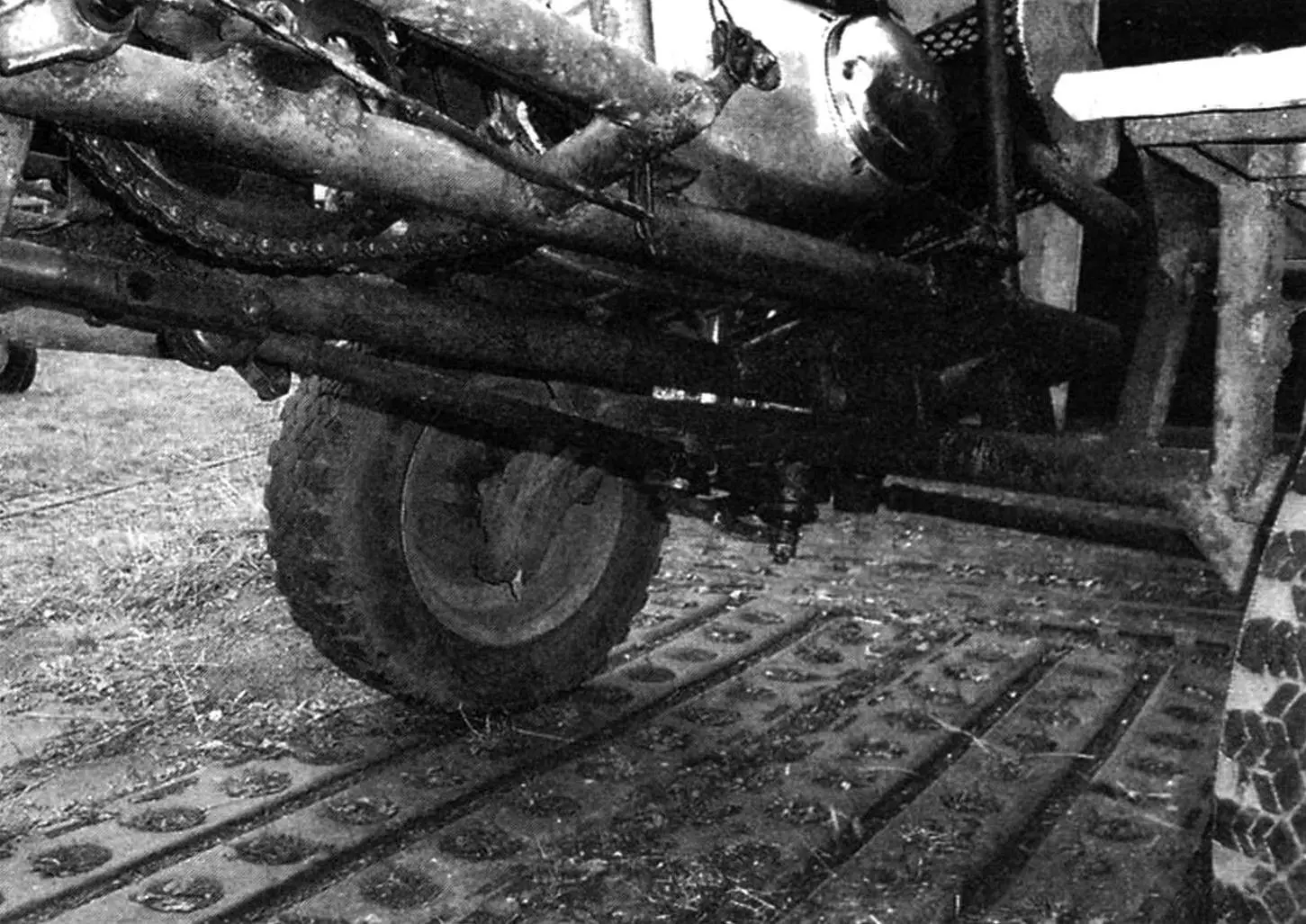
Between the front cross members, two brackets made from U-shaped profile 50x25x50 mm are welded at the ends. The front drive wheel hubs are bolted to them. Ribs (from 25×25 angle) of the reducer frame box for mounting the main drive reducer are welded to the longitudinal members.
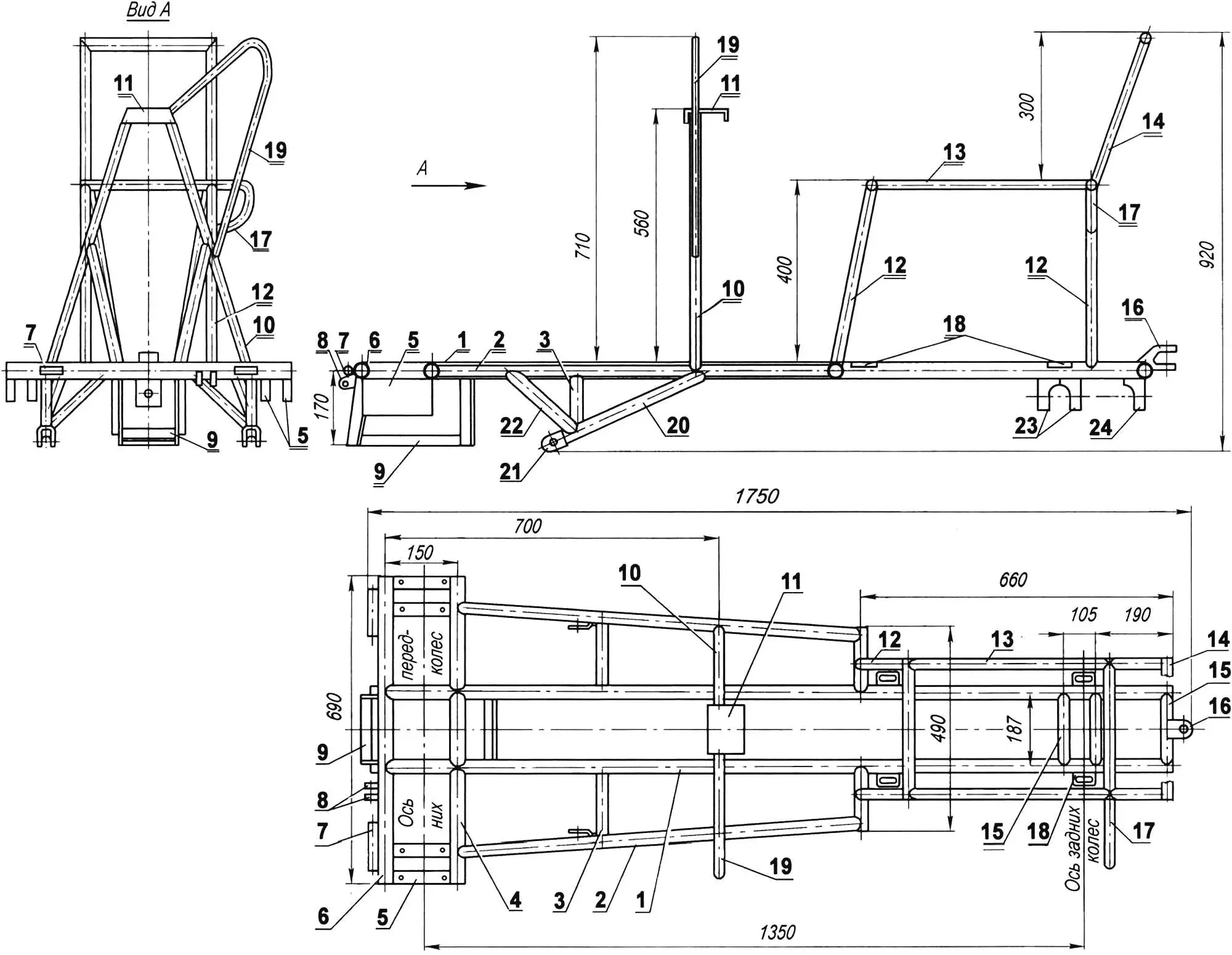
1 — longitudinal member (pipe 42×3, 2 pcs.); 2 — longitudinal beam (pipe 32×2.5, 2 pcs.); 3 — transverse strut of blade mounting post (pipe 32×2.5, 2 pcs.); 4 — second front cross member (pipe 42×3); 5 — hub mounting bracket (U-shaped profile 50x25x50, 2 pairs); 6 — first front cross member (pipe 42×3); 7 — body suspension bushing (pipe 22×2, 2 pcs.); 8 — cable roller mounting lugs for body lifting (sheet s5); 9 — reverse reducer frame box (angle 25×25, 2 pcs.); 10 — steering post (pipe 32×2.5); 11 — post crosspiece — instrument panel (bent channel No. 10); 12 — seat legs (pipe 32×2.5, 4 pcs.); 13 — seat frame (pipe 22×2, 2 pcs.); 14 — seat back frame (pipe 22×2, 2 pcs.); 15 — rear cross member (pipe 42×3, 3 pcs.); 16 — towing device — fork; 17 — rear lamp mounting console; 18 — engine subframe mounting lug (sheet s5, 4 pcs.); 19 — headlight mounting console-loop; 20 — hanging blade post (pipe 42×3); 21 — blade suspension eye (U-shaped profile 40x50x40, 2 pcs.); 22 — longitudinal strut of hanging blade post (pipe 32×2.5, 2 pcs.); 23 — rear axle beam suspension brackets (U-shaped profile 40x50x40, 2 pcs.); 24 — rear axle strut suspension bracket (U-shaped profile 40x50x40)
U-shaped profile brackets for rear axle suspension are welded to the rear cross members, and two more lugs forming a fork are welded to the closing cross member at the rear.
A steering post with a headlight bracket is welded to the top of the frame (approximately in the middle of its length), and in the rear part — seat legs and frames for the seat and its back. The upper (horizontal) part of the steering post — the crosspiece is made from a wide channel — it serves as the instrument panel. Hanging blade posts with eyes (reinforced with struts) are also welded from below in the front part, to which the bulldozer blade is suspended.
Later, brackets for the cable winch handle for raising (lowering) the blade, reverse shift levers, and the mechanism to prevent body tipping (locking) were welded to the steering post “in place”. The mechanism itself is a lever with a slot that engages the protruding flange of the body frame angle, and a locking button. I draw special attention to the necessary reliability of the entire unit — spontaneous body tipping while moving threatens serious trouble, especially when moving downhill. The steering mechanism from the SZD motorized wheelchair is mounted under the post between the longitudinal members on two brackets.
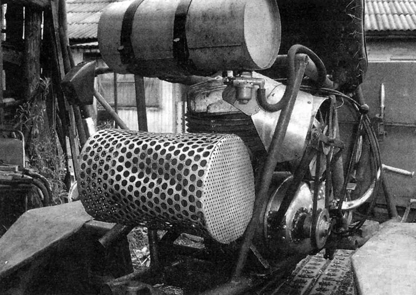
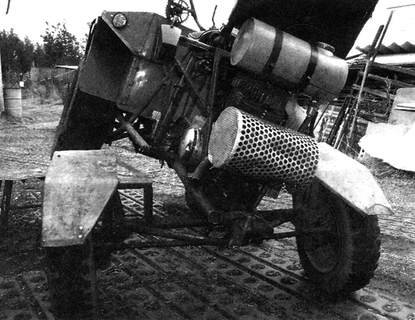
An engine from the Izh-Planeta-3 motorcycle with a power of 18 hp is used as the power unit of the chassis. I equipped its cylinder with a homemade forced air cooling device with an 8-blade fan in a housing. The fan is driven in rotation from the extended engine crankshaft through a V-belt drive (from a washing machine). The engine is located under the seat and is attached to the frame through special welded brackets that allow it to be moved using a screw to tension the transmission chains.
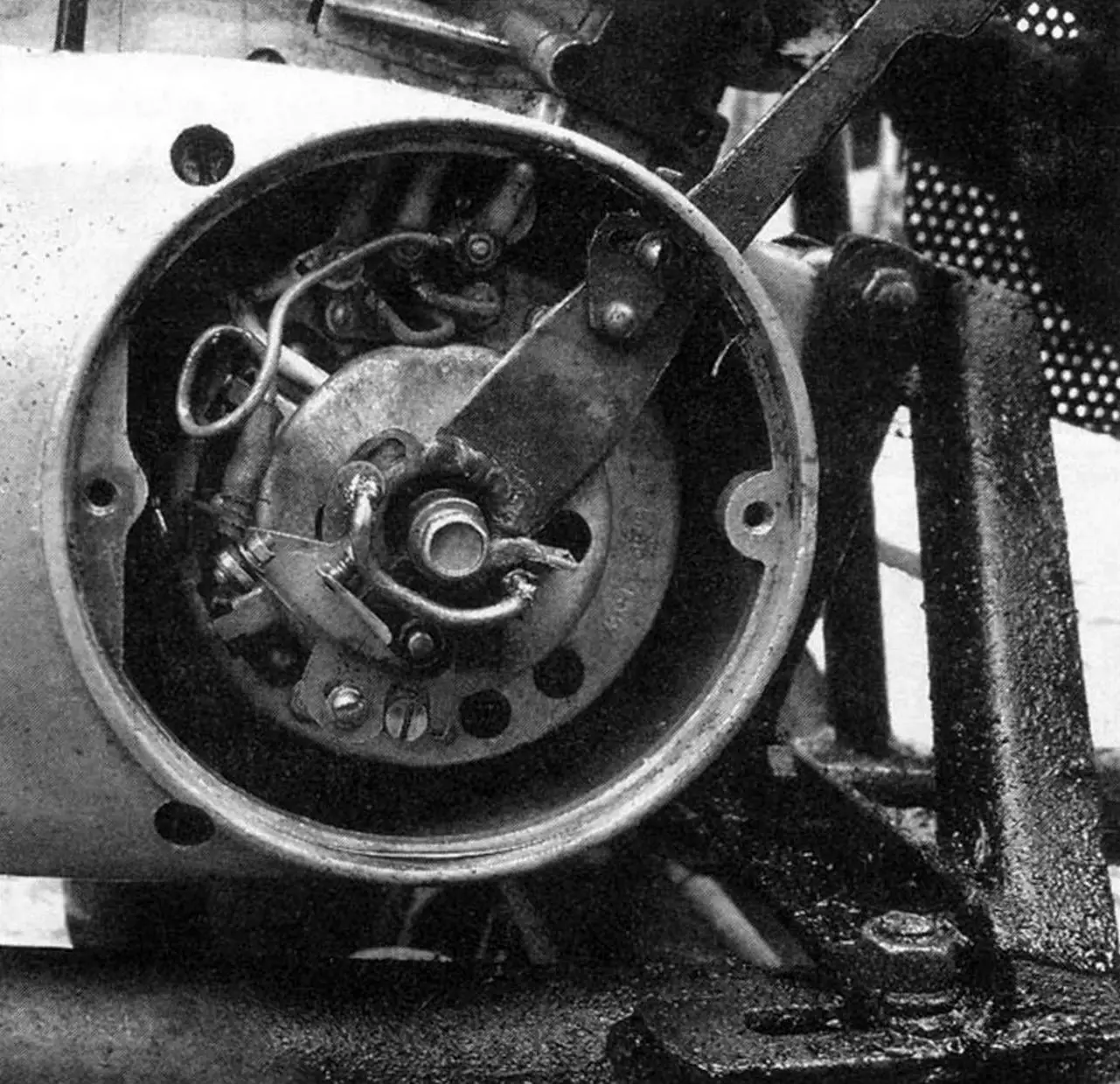
The engine’s standard ignition system has been modified. Instead of a “single-spark” coil, a “double-spark” one from a K-750 motorcycle is installed, and accordingly, a second spark plug on the cylinder head.
Operation has shown that the decompressor is no longer needed for the engine; it is sufficient to monitor the cleanliness and serviceability of the fuel system and carburetor. Engine failures due to lack of spark in the ignition plug have practically disappeared, which was common before. The breaker plate mounting has also been changed — it is now mounted on the generator shaft with a sliding fit and can rotate through a certain angle, thereby adjusting the ignition. The breaker plate is attached to the generator stator using extended screws, which are then secured using wire brackets soldered to them.
Owners of single-cylinder “Izh” motorcycles are well familiar with kickstarter lever kickback, which sometimes leads to serious injury. This modification completely eliminates this unpleasant phenomenon. Before starting the engine, the plate is moved to “late” ignition using a lever extended through the generator housing, and after the engine warms up, it is returned to place. On the lever, at the point where it exits the generator cover, there is a locking flag that engages a slot on the cover with its protrusion, thereby ensuring a stable position of the plate lever at the required ignition angle. For precise adjustment of the breaker contact opening moment, the flag is made movable. All single-cylinder “Izh” engines I use have been modified according to this principle.
The muffler is from the Buran snowmobile; it is compact and quite effective. Pieces of exhaust pipes with union nuts from the “Izh-P3” are welded to the standard inlet pipes of the muffler.
Since the engine is located in the rear part of the chassis frame, and the drive wheels are at the front, the transmission of torque from the power unit to the main drive had to be accomplished through a two-stage chain drive with an intermediate reducer. The chains are widened, combine-type. From a combine harvester comes the large (Z = 53 teeth) sprocket on one end of the intermediate shaft. A sprocket Z = 15 from the rear wheel of an Izh motorcycle is installed on the other end of the shaft. In addition, a brake drum (welded to the motorcycle sprocket) from a Vyatka scooter wheel is mounted on the intermediate shaft.
The brake cover is homemade, and the pads are standard scooter ones. The shield is attached to the frame through two brackets in the form of legs. At the same time, the possibility of orientation (slight movement and rotation) of the shield with pads relative to the drum is provided. The intermediate reducer itself can also be moved along the frame longitudinal members to tension the chain going to the main drive.
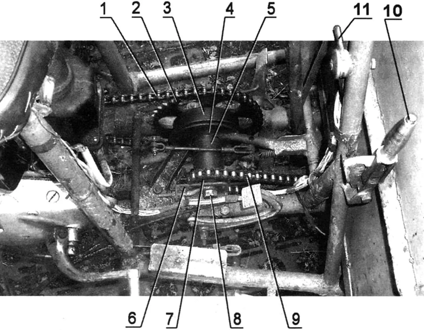
1 — first stage chain (t = 19.05); 2 — large sprocket (Z = 53, from combine); 3 — brake drum (from SZD motorized wheelchair); 4 — brake shield with pads; 5 — bearing housing (from combine); 6 — tensioning device; 7 — small sprocket (Z = 15, from Izh motorcycle); 8 — intermediate shaft; 9 — second stage chain (t = 19.05); this photo clearly shows the body locking lever (item 10) and the “throttle” control (item 11)
The main drive (or reverse reducer) is from the Ant cargo scooter. It has been modernized: instead of standard narrow differential and reverse gears, widened ones from the SZD motorized wheelchair are installed. Of course, if you strictly monitor the load mass each time and do not abuse the traction forces of the power unit (and it, by the way, is capable of heavy loads), then these modifications to the reverse reducer are not required. The drive sprocket of the main drive (which is also the driven sprocket of the second stage of the chain drive) is also taken from the motorized wheelchair.
In principle, the reverse reducer can also be used from the SZD wheelchair. However, its reverse idler gear is mounted on the shaft on a sliding bearing (bronze bushing). With intensive use of reverse (which is not uncommon in homestead tractor operation), such a bearing quickly fails, and it is better to immediately replace the bushing with a rolling bearing.
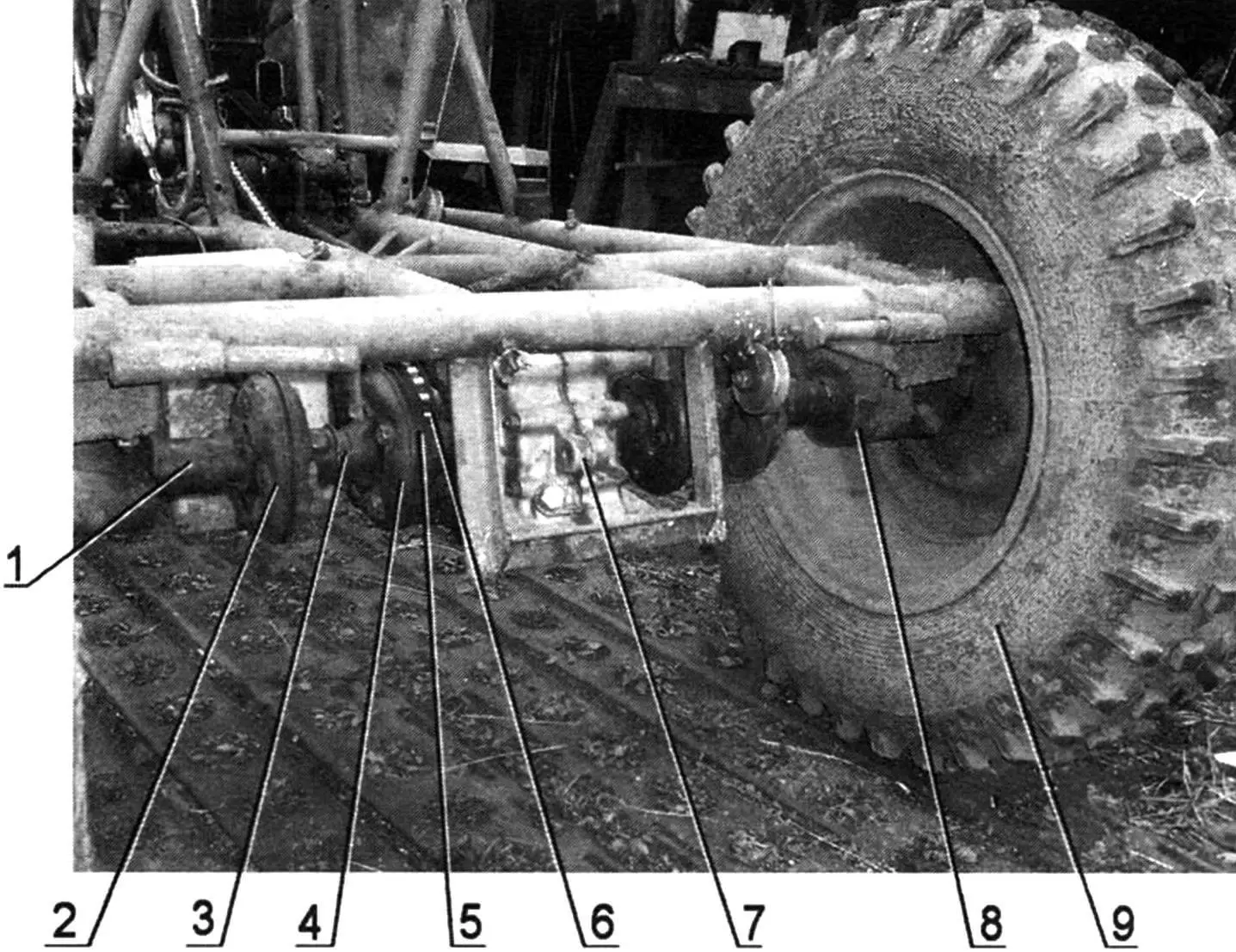
1 — splined coupling segment (2 pcs.); 2,4 — Hooke’s joints (4 pcs.); 3 — splined shaft segment (2 pcs.); 5 — main drive drive sprocket — second stage chain drive driven sprocket (Z = 21); 6 — second stage chain drive chain (t = 19.05); 7 — main drive—reverse reducer; 8 — hub (from DT-75 tractor, 2 pcs.); 9 — drive wheel
The transmission of rotation from the main drive to the drive wheels is accomplished through a pair of rather complex half-shafts, each consisting of two standard flexible cardan joints with a short splined shaft between them, with a splined coupling segment welded to the second joint (closer to the wheel), which connects to the hub shaft. The latter parts (splined coupling, shaft, and hub) are from a DT-75 tractor starter. A flange with studs for mounting the drive wheel is welded to the end of the hub shaft.
Of course, the half-shaft is quite complex, and if, for example, an extended hub is made, then the second joint would not be needed. But I proceeded from what was available.
The front drive wheels are from a UAZ vehicle. But their tires have been modified into a deep “checkerboard” pattern for better traction on plowed land, off-road, and in mud. At the same time, the tires have also become significantly lighter. I believe that such tires are very suitable for all-terrain vehicles. The technology for their manufacture is described in No. 9’2008 of “Modelist-Konstruktor”.
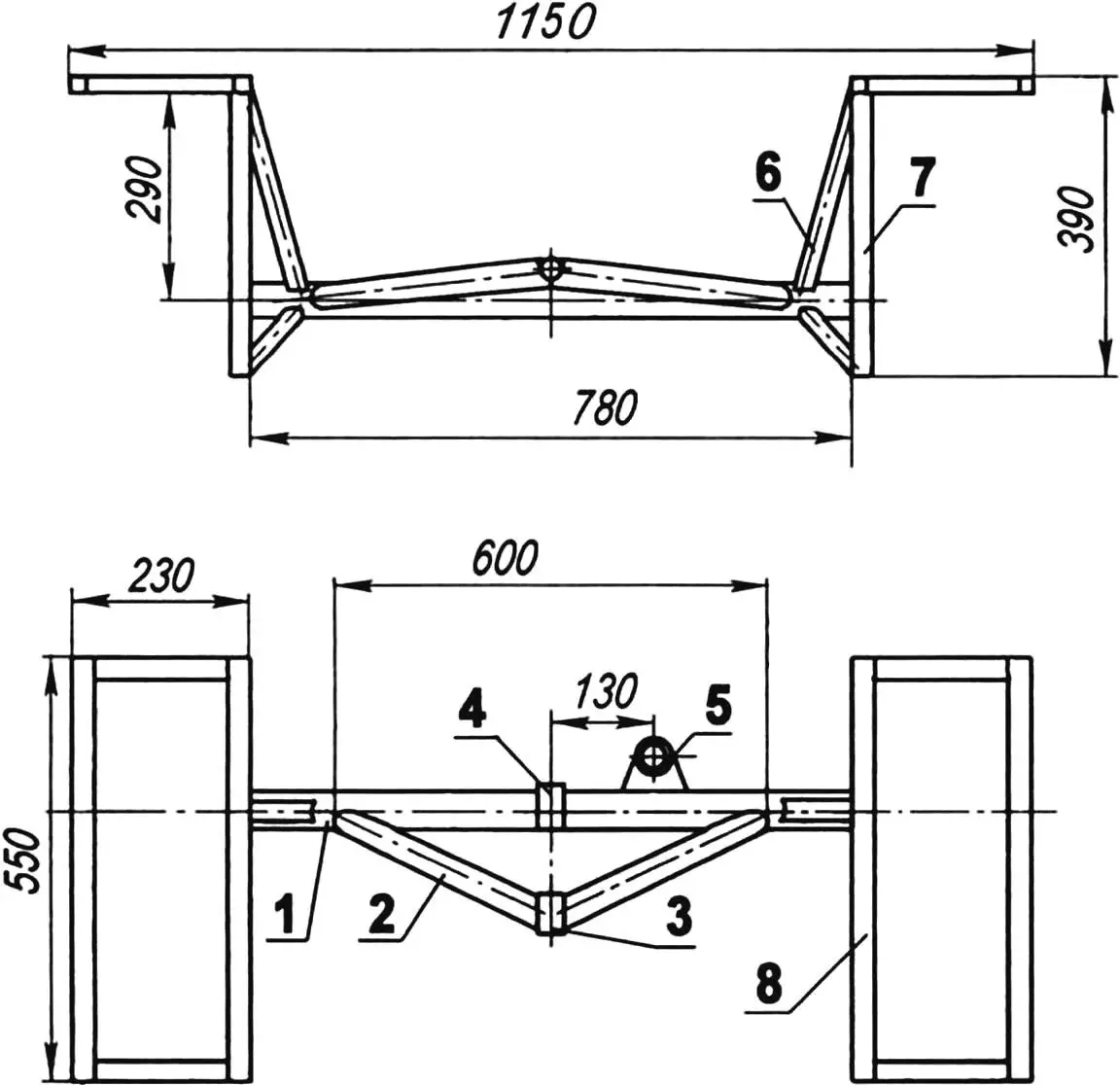
1 — beam (pipe 42×3); 2 — strut (pipe 32×2.5, 2 pcs.); 3 — strut suspension bushing (pipe 22×2); 4 — beam suspension bushing (pipe 22×2); 5 — L-shaped steering rod lever bearing housing (from combine); 6 — steering knuckle post strut (pipe 20×20, 4 pcs.); 7 — steering knuckle post (channel No. 6, 2 pcs.); 8 — rear fender-splash guard frame (pipe 20×20, 2 pcs.)
The rear axle of the chassis has the shape of an isosceles triangle, because two identical struts made from 32×2.5 mm pipe with a bushing at the convergence point are welded to the beam (42×3 mm pipe). Exactly the same bushing is also on the middle of the beam at the top. Through these bushings, the rear axle is suspended on frame brackets using cotter-pinned kingpins. Such suspension allows the rear (and front) wheels to well follow the path profile without twisting the frame, and prevents any of them from hanging over depressions.
Posts made from channel are mounted on the ends of the rear axle beam, to which the steering knuckles are attached, and brackets made from angles are welded to the top of the posts for mounting rear fenders-splash guards here.
The rear steerable wheels and steering knuckles (as well as the steering mechanism and steering rods) are from the SZD motorized wheelchair. Brake mechanisms have been removed from these units as unnecessary. Of course, the wheelchair wheels are much smaller in diameter than the UAZ ones, which reduces cross-country ability, but with them maneuverability is higher, and this is much more important for a homestead machine.
A cup is welded to the rear axle beam, to the right of the middle, in which an L-shaped lever is mounted on bearings, one end of which is actuated by a longitudinal rod from the steering mechanism rack, and the other end moves two transverse steering rods of the corresponding wheels. Due to the large travel of the beam when the tractor moves over difficult sections of the path, the diameter of the rear wheels cannot be increased without increasing the width of the rear axle due to the fenders hitting the engine at extreme positions.
The tractor body is welded. Its frame is made from various angles and sheathed with sheet steel 1.5 mm thick. All corners along the top of the body are rounded to prevent injury.
Approximately 1/3 of the body length from the front side, two bushings are welded from below to the transverse angle of the frame, through which it is suspended via kingpins to eyes welded to the first cross member of the tractor frame. The front drive wheel fenders are welded directly to the body, have several functions — they expand the loading area, serve as protection from splashes, and increase the rigidity of the body itself, since the tractor sometimes has to transport loads of significant mass.
For transporting bulk materials, I place most of the volume on the front part of the body, which allows it to be easily tipped forward almost vertically without additional devices. The inclined front side and fenders installed with an inward tilt promote almost complete unloading of materials, especially if the tractor is put in reverse.
The electrical equipment is standard 6-volt. The carburetor and air cleaner are also standard. The ignition switch toggle simultaneously connects the battery. A toggle switch for the headlight and rear lamp is also located on the panel. Control lamps for “neutral” and generator operation are also installed on it. Reflectors installed on the body also increase safety.
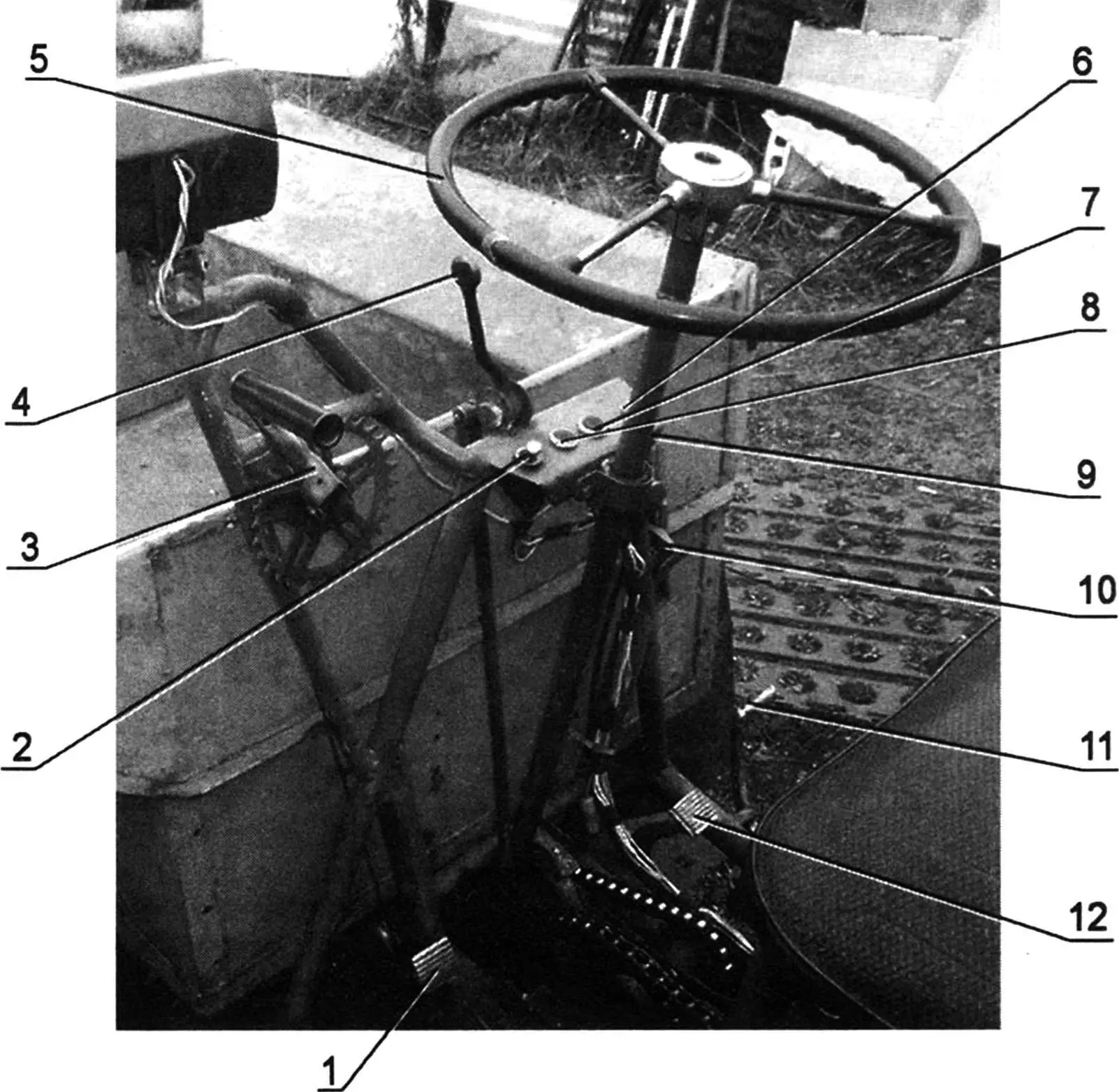
1 — clutch pedal; 2 — ignition switch toggle; 3 — body lift-lower winch; 4 — reverse control lever; 5 — steering wheel; 6 — headlight and rear lamp switch toggle; 7 — generator operation indicator lamp; 8 — neutral indicator lamp; 9 — air corrector control location; 10 — body locking lever; 11 — “throttle” pedal; 12 — brake pedal
The controls include pedals: “throttle”, brake, and clutch. It should be noted that the “throttle” pedal is additionally spring-loaded: this is necessary for more precise engine speed control under dirty conditions and when driving off-road. A reverse control lever is installed on the panel in front of the steering wheel. Switching of the reverse reducer is performed through two rigid rods and an intermediate L-shaped lever installed above the steering mechanism. The lever on the reverse is spring-loaded for better fixation in extreme positions under vibration conditions.
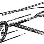
The manual winch for raising and lowering the blade is a roller with a small drum with flanges that prevent the cable from coming off. The roller rotates in a cup with bearings; the cup is welded to the “headlight” bracket. The winch control handle is pressed by a leaf spring against a gear wheel welded to the roller cup-hub and serves to lock the handle using a tooth that engages the gear depressions (the gear itself is from a children’s bicycle). The cable is wound onto the winch drum through a roller installed at the bottom near the edge of the body and then through the same roller located on the first cross member of the tractor frame, pulls the blade frame cross member. The blade is suspended to the tractor frame in two bracket-eyes of the hanging posts. For this, there are bushings on the ends of the blade suspension supports, which are inserted into the bracket eyes and secured here with kingpins with cotter pins. The blade itself is simple; I only want to note that increasing its mass is undesirable — this leads to increased effort on its lifting handle.
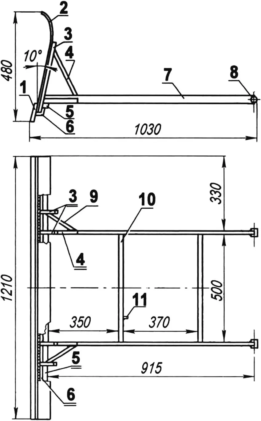
1 — scraper (rubber strip s10); 2 — shield (AMC s3.5); 3 — post (pipe 25×25, 4 pcs.); 4 — post strut (pipe 25×25, 2 pcs.); 5 — additional cross member (pipe 50x25x2, L= 1210); 6 — main cross member (angle 45x45x3, L=1210); 7 — suspension support (pipe 50x25x2, 2 pcs.); 8 — blade suspension bushing (pipe 30×8, 2 pcs.); 9 — additional cross member strut (pipe 25×1, 2 pcs.); 10 — movable support cross member (pipe 30x25x1.5, 2 pcs.); 11 — cable mounting eye
For this reason, the suspension supports with cross members that make up the blade frame are made from thin-walled pipes except for the lower angle of the main cross member, and the shield is made from duralumin. Removable rubber strips are attached along the bottom of the blade; they have a 30 — 40 mm extension at the bottom to soften impacts against bumps. In the upper position, the blade is pressed against the body and does not swing when the tractor moves. Of course, with the blade installed, the body can no longer tip, but in winter, transporting bulk loads is extremely rare, and if needed, the blade can be removed in five minutes. For better wheel traction when clearing snow, ballast (20 — 30 bricks) is placed in the body. Anti-slip chains can also be used.
As mentioned, the driver’s seat folds down, providing access to the spark plugs, tool box, and coil, as well as facilitating access to the carburetor. The standard relay-regulator and terminal block are also secured inside the seat frame. Behind the seat, a 6-liter fuel tank is secured using clamps on a plate bracket welded to the seat frame. Fuel supply is by gravity, through a standard tap.
The kickstarter lever is from “Izh-Jupiter”; it can fold, not interfering with the driver engaging gears with an extended lever. The fuel corrector control is mounted on the vertical tube of the steering post; the drive from the corrector to the carburetor throttle valve is by Bowden cables. The clutch pedal is connected by a rod to an L-shaped lever; the lever pulls the clutch release cable with its other end. The brakes are actuated from the pedal through two rods with an intermediate rocker. Both rods have length adjustment. To replace the pads, the brake cover can move along the second rod tube.
In conclusion — about the features of chassis control. One should not brake sharply, as this leads to peak loads in the transmission. “Spiked” tires in summer have high traction (especially on a loaded tractor), and the brake drum is easily locked. It is dangerous to maneuver in reverse at high speed: with rear-steered wheels, “steering feel” disappears. It should be taken into account that reverse is noticeably faster than forward, and therefore, traction is less. On loose soils, an unloaded tractor can dig in on climbs. In such cases, one should move in reverse or place ballast in the body.
The tractor’s dimensions and maneuverability allow it to literally “squeeze into” any “gap”, and forward unloading by tipping the body and subsequent backing away are very convenient on a personal homestead, where, as usual, all area is maximally utilized. The low body height from ground level is convenient for loading-unloading, and the low center of gravity location contributes to tractor stability on slopes.
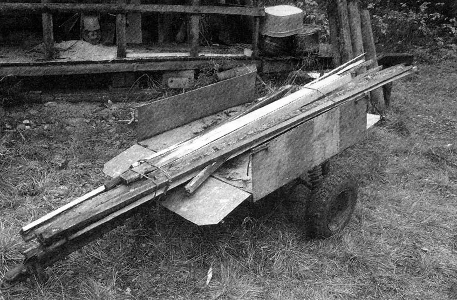
The mini-tractor is also capable of towing a trailer with a load capacity of up to 500 kg. The front and rear sides of the trailer are foldable, so it can also be used as a log trailer for transporting long loads.
I tried mounting a plow on the chassis and plowing. It worked out quite well. But I also have a motor winch for these purposes.
A. KOKSHAROV
Recommend to read
 THE CAR JUNIOR
The model aircraft easier... Bought a compression motor, collected from reechek Yes nervures wing, planed boards from lime simplest fuselage and fly the model! And this is the simplest...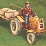 WE MADE A TRACTOR!
Building a tractor-little young designers not deny myself the pleasure to use his own name initials. So there on the hood of metaphora three polished letters SAP, which means Sergei and...
