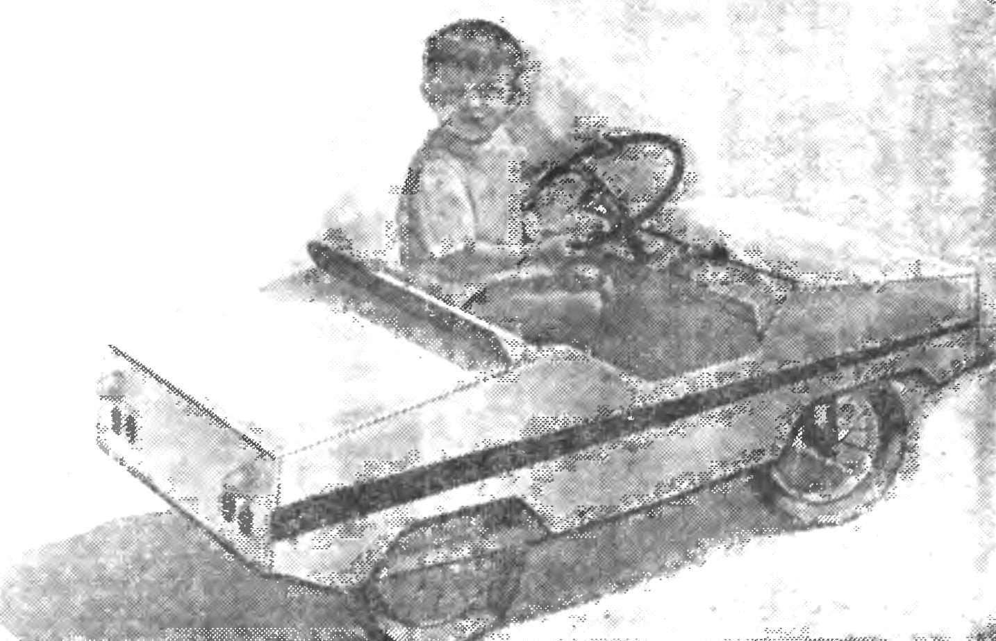
 This little car (Fig. 1) I did back in 1972, and it is already my second son, Sasha. He was only three years, but he leads the electric car is almost like a real chauffeur. The car became a favorite toy of kids all around, and how else — steering, brakes, lighting, sound signal, turn on the rear — all on this car!
With a fully charged battery the electric car can run for about ten hours and drive during this time 50 km.
Machine frame structure. The frame is welded from steel angles 20×20 mm. Rear axle is attached directly to it, and the front — to pivotally connected to frame cross beam (Fig. 2). On it with two pins pivotally mounted two axles of the steel strip 25 mm wide and 4 mm thick. Steering lever type directly into the steering trapezoid. Steering column — from scooter, as the steering shaft with cut plug (instead welded oneplace lever). Traction as cross-section, and oneplace connecting the lever with the a-line is made of eight millimeter steel rod. On lever steering column mounted universal joint.
The drive wheel of the electric car is the right rear; unlike other, standard samokatnaya, it has a solid disc.
On a driving wheel with four bolts with M8 thread pinned homemade sprocket Z = 60.
As engine I used the alternator from the car “Moskvich-400”, but in principle it would fit any other voltage 6 V and a current of 20 A (e.g., from motorized С3А). It should, however, replace the wire winding on the thicker.
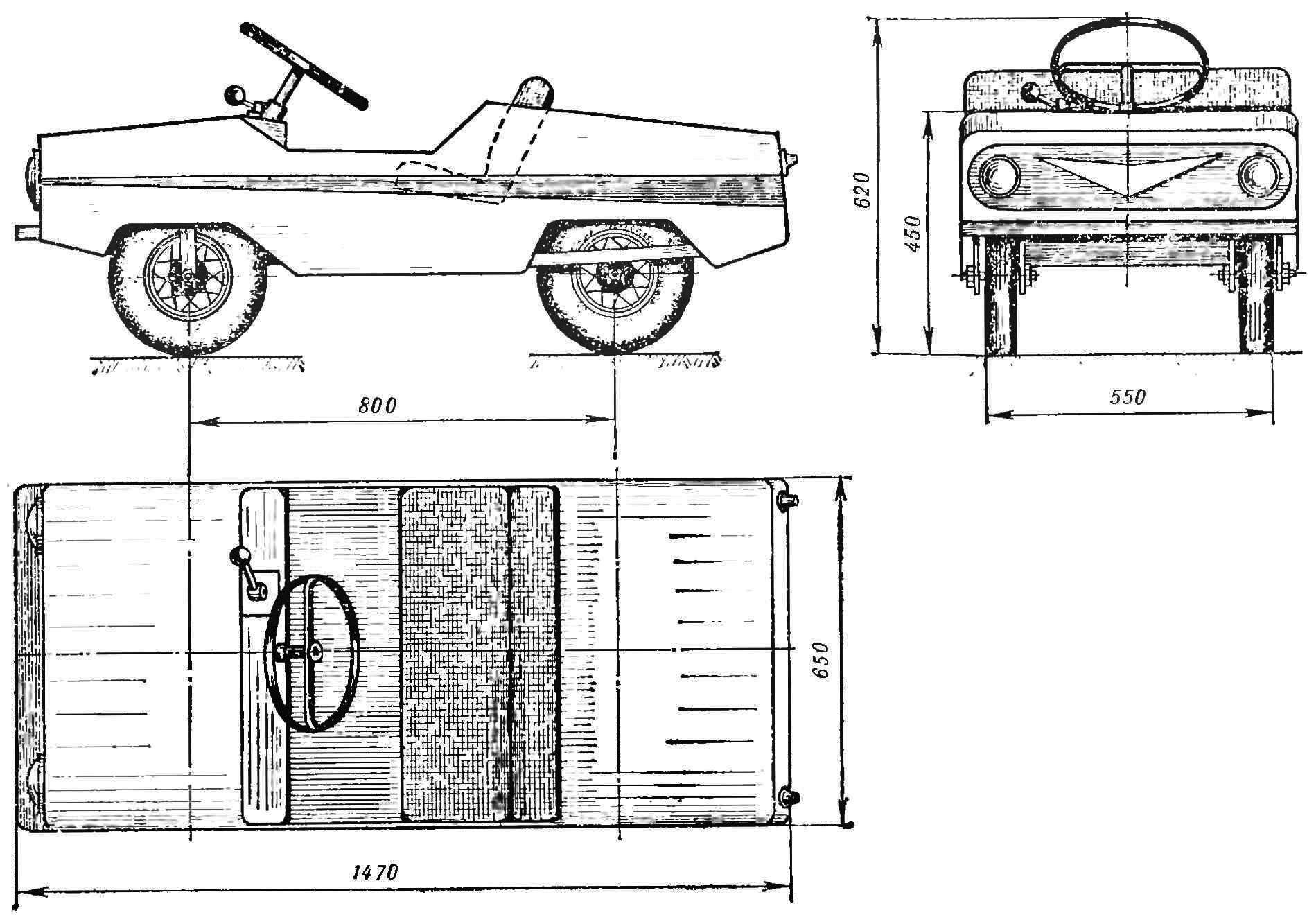
Fig. 1. Scheme of the electric vehicle A. Stepanyugin.
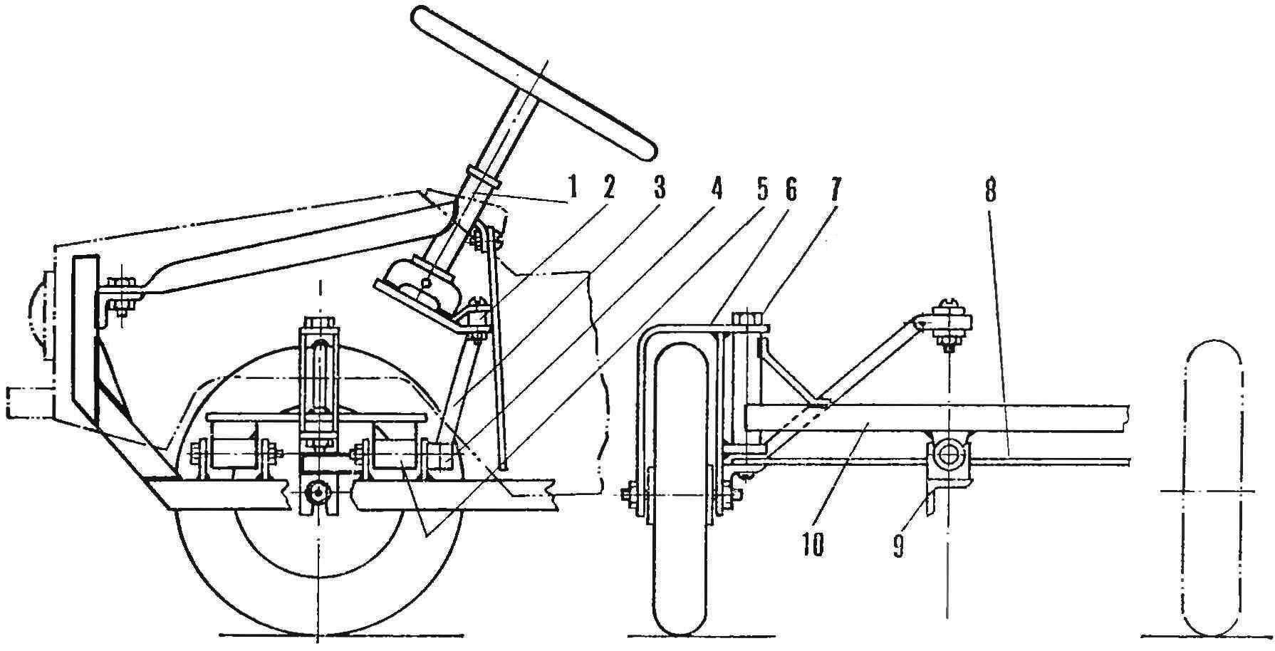
Fig. 2. Front axle:
1 — steering column (the part of the frame from scooter), 2 — the lever of a steering column, 3 — tie rod (steel rod Ø 8 mm), 4 — arm axle, 5 — joints of the front beam, 6 — swivel pin-plug, 7 — pins, 8 — transverse thrust steering linkage, 9 — frame, 10 — cross beam.
This is done as follows: from the generator you must remove the poles and then replace the coil. New better spooling of the wire of brand of PEV-2 in diameter of 1.5—2.0 mm. this Operation is easier to produce, making the pre-pattern, or, in extreme cases, by driving in the right Board, four nails (the size of the poles). The number of turns is not critical (wind to fill!), just need to make sure that it was the same in both windings.
The finished coil must be isolated with tape and put into place. You should connect them in parallel, and the joints are carefully soldered and connected to the terminals I and W of the generator. Don’t forget when connecting the windings to observe polarity!
For gear I used the gear from the engine of a moped “Riga-3” — small, 12 teeth from the clutch disk and most, 57 teeth, with the secondary shaft. From the same engine and drive sprocket of chain transmission.
Structurally, the motor, reducer and brake combined into a block (Fig. 3). To this end, the eyelets of the engine is fixed a steel plate with a thickness of 4 mm and it is welded on the bearing housings — they are rotating the shaft with netgenie to it by the sprocket and gear wheel. Interfaced with the latter gear is mounted directly on the motor shaft. It is mounted and the impeller is cooled and the brake disc Ø 90 mm to 10 mm thickness. the brake is a lever — it is pressed against the outer surface of the brake disc. When braking is triggered the limit switch, the motor is de-energized.
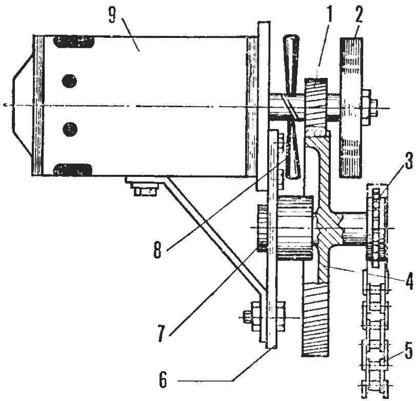
Fig. 3. The power unit of an electric vehicle:
1 — pinion gear (Z = 12), 2 — brake disc, 3 — drive sprocket of chain transmission, 4 — toothed wheel gear (Z = 57), 5 — Bush roller chain, 6 — base plate reducer, 7 — intermediate shaft 8 — impeller air-cooling the electric motor 9, the motor.
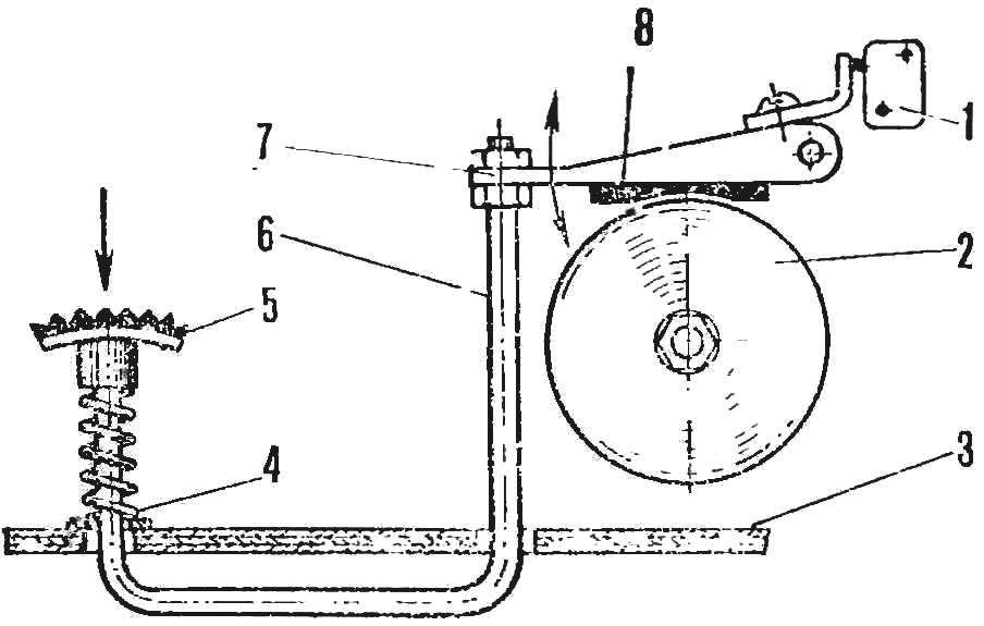
Fig. 4. The scheme of the motor brake of the electric car:
1 — button, 2 — brake disc, 3 — bottom, 4 — spring, 5 — brake pedal 6 — thrust, 7 — brake pad, 8 — friction pad.
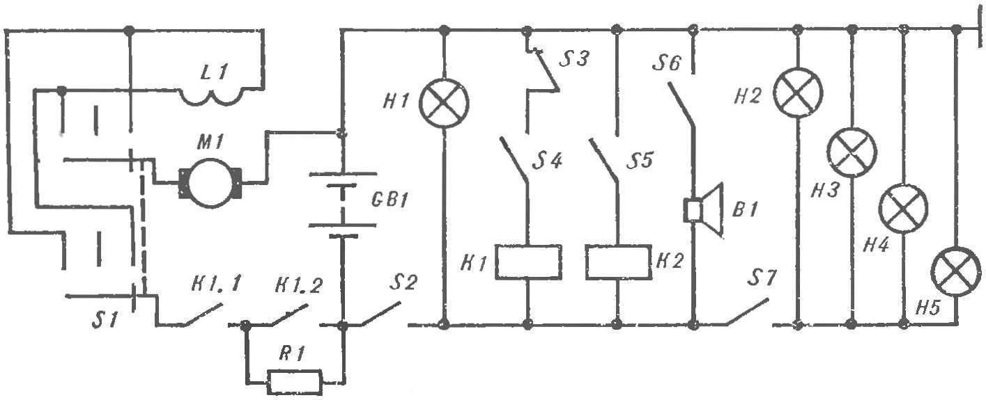
Fig. 5. Schematic diagram of the electrical equipment:
L1 — excitation coil, S1 is the switch of the reversing motor (ck-20), K1.1, K1.2 — power relay contacts K1 and K2, S2 switch control circuit, S4, S5 — switch of a pedal of “gas”, S3 — microswitch brake pedal, B1 — signal S6 — signal S7 — lighting switch GB1 — battery (55 Ah), K1, K2 — relay (starter relay or horn), H1 — control lamp H2 H3 — headlight, H4, H5 — tail lights.
Smooth starting of the machine provides included in the motor circuit resistance; in the future it zamorachivatsya, and the engine uses up battery power. Structurally, it is provided with two limit switches associated with a homemade pedal. To reverse the engine used switch type up-20, changing the polarity of the field winding.
Electric vehicle body is made of plywood, fastened in the corners of the slats with glue and screws. With the frame it is connected by screws M5.
The battery is installed between the rear wheels. Access to it, and also to the engine through the open rear hood and removable seat.
As shown by many years of operation, the car was very reliable and durable.
A. STEPANYUGIN, Divnomorskoe village, Krasnodar region
Recommend to read
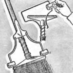 NEAT “LAZY”
The one who washes the floors with the help of this simple device for clamping the cloth, knows the ends of the metal sticking pose a danger to the furniture: if there is careless...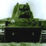 HEAVY TANK SMK
The development of anti-tank artillery in the second half of the 1930-ies, in particular the appearance of the guns of calibre of 37 — 47 mm, has questioned the effectiveness of the use...
