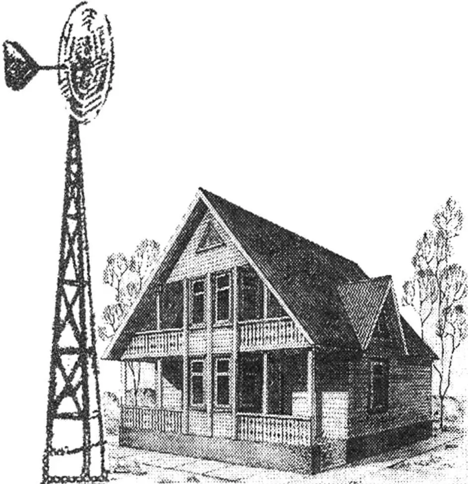
Wind has always been considered a symbol of inconstancy, and attempts to convert its energy into electrical energy most often led to results that were not very encouraging. Indeed, everyone expects stability from a source of electrical energy: flip a switch — and the light bulb lights up. But wind, alas, is changeable. However, it can be made a reliable source of electrical energy if one uses a long-developed scheme with an intermediate energy storage device — a battery.
During the day, the wind engine rotates an electric generator, which, with the help of an electronic device, charges a battery. Depending on wind strength and energy consumption, the optimal charging current is set and the supply voltage is stabilized regardless of the generator’s rotation speed. In today’s selection, readers are offered two wind power stations (WPS): a classic one — with a horizontal axis and a rotor one — with a vertical axis of rotation.
“Disk”
The WPS is assembled on the basis of automotive units — a 12-volt generator and a battery capable of providing a country house with lighting (three to four 20-candle lamps), as well as energy to power a portable TV and other 12-volt electrical appliances.
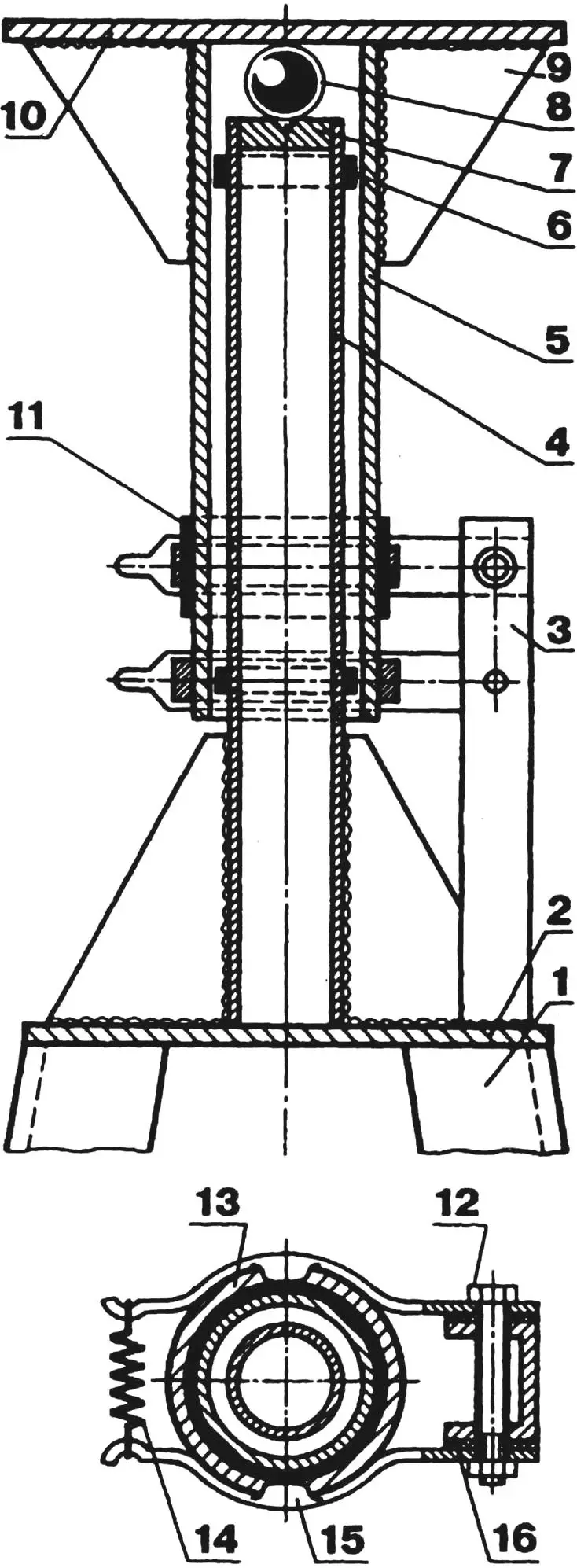
To rotate the generator (for example, a Zhiguli one, having a delivery current of 42 A at a rotation speed of 5000 rpm), a wind wheel with a diameter of 1500…1800 mm will be required. The generator drive is carried out through a chain multiplier (accelerating gearbox) with a gear ratio of 3…4.
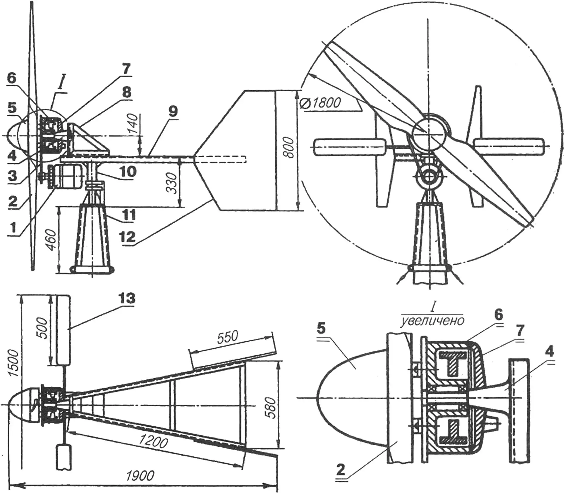
1 — electric generator type G-221; 2 — two-blade wind wheel; 3 — chain drive of the multiplier; 4 — cantilever axis of rotation of the wind wheel; 5 — wind wheel hub fairing; 6 — wind wheel hub (motorcycle brake drum); 7 — brake shield with brake pads; 8 — bracket of the cantilever axis of the wind wheel; 9 — frame; 10 — swivel-collector unit; 11 — support; 12 — guide fins; 13 — automatic brake device
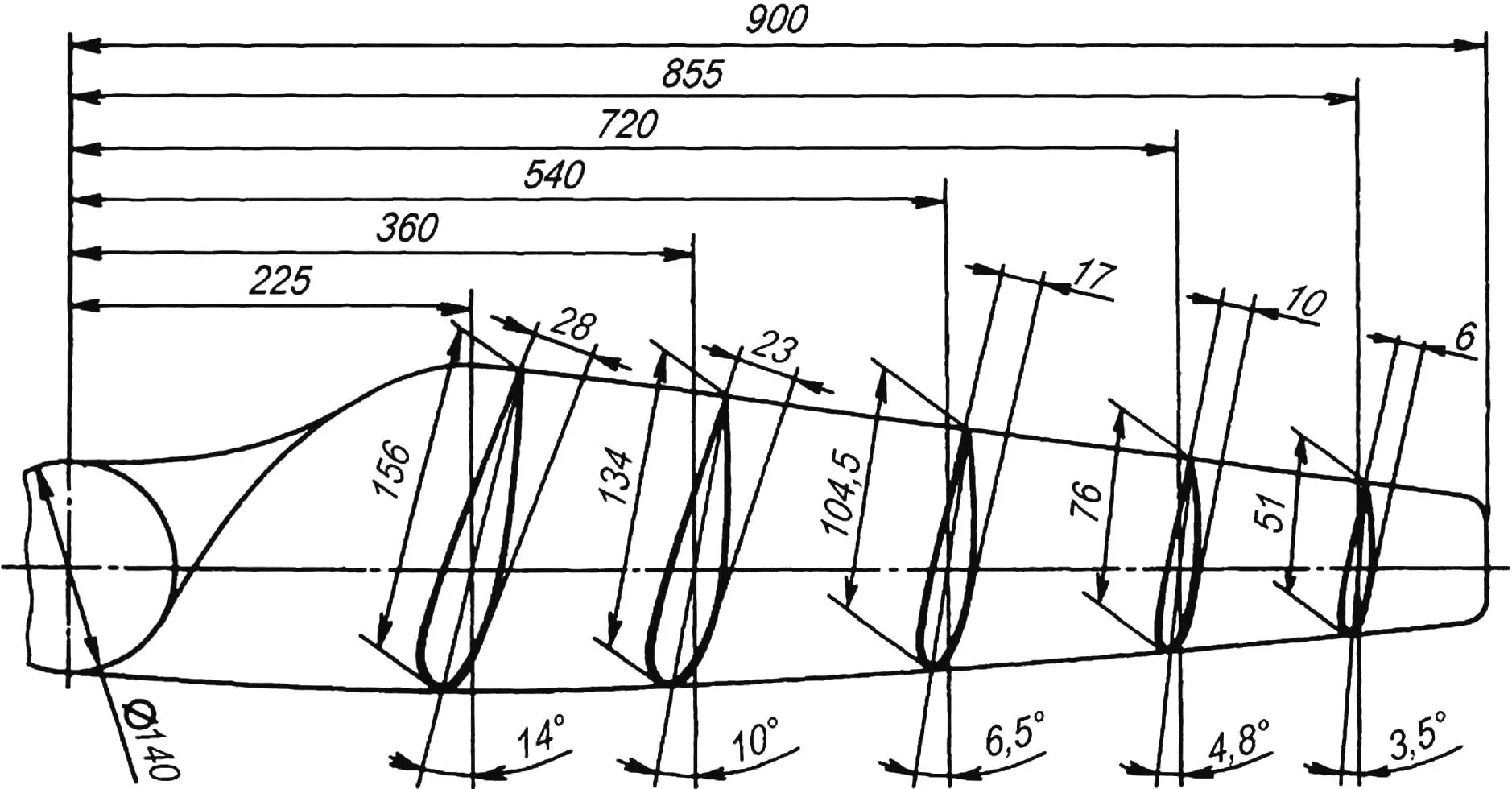
The wind wheel blades are best made from birch or pine blocks. First, a blank of the air propeller is cut out, representing its plan projection with a 5-mm allowance. The blade contours with control section planes are marked on it. Be careful when manufacturing the air propeller profile — the efficiency of the wind installation, or, what is the same, the energy output of the electric generator, depends on how accurately it is made.
To obtain a blade of the required profile, first, lines of the rear and leading edges of the blade should be applied to the propeller blank, determining the angle of attack of each of the sections. Then, using semicircular chisels and a rasp, cut “markers” — profile sections in the control section zones and color them with a colored pencil. Wood is removed between the “markers”; at the same time, the correctness of the blade profile is controlled using a ruler placed on adjacent arcs. Sections colored with a colored pencil should remain untouched during processing.
The finished air propeller is sanded and fixed on the hub, which uses a motorcycle wheel brake drum: this allows having not only a compact bearing unit but also a simple automatic brake device.
After installing the air propeller on the hub, the latter must be balanced. For this, the propeller’s rotation axis is fixed in a vise and the heavier blade is lightened using a rasp and sandpaper. A correctly balanced propeller should stop after rotation in any position.
The finished propeller is coated with several layers of parquet varnish with intermediate sanding and finally fixed on the hub.
The wind engine frame is welded from steel angles with a cross-section of 40x40x3 mm. A bracket is also assembled from the same angles, in which the air propeller’s rotation axis is fixed. The guide fins (“tail”) of the windmill are cut from plywood about 6 mm thick. The swivel device hinge is a steel ball between a support heel pressed into the stationary post and the docking platform of the movable post. A nylon bushing is installed on the free end of the latter.
As already mentioned, rotation from the wind wheel to the generator is transmitted through a chain multiplier with a gear ratio of 3…4. For this, bicycle sprockets are used: between the hub and the air propeller — the driving one, and on the electric generator shaft — the driven one. Mounting the generator using standard brackets allows ensuring optimal chain tension.
The wind generator must be equipped with an automatic brake that prevents the air propeller’s rotation speed from increasing above the permissible level when the wind suddenly intensifies. The simplest option is using a motorcycle brake device. For this, a bushing with a tubular rod welded to it is placed on the cam axis instead of the brake lever. Two plywood blades are fixed on the latter. The standard spring that tightens the brake pads is replaced with another, less rigid one. The spring parameters are selected depending on the area of the brake device blades and the rod length. Braking of the propeller hub should begin at a wind speed of 12… 15 m/s, and in very strong wind, the wind wheel will stop by itself.
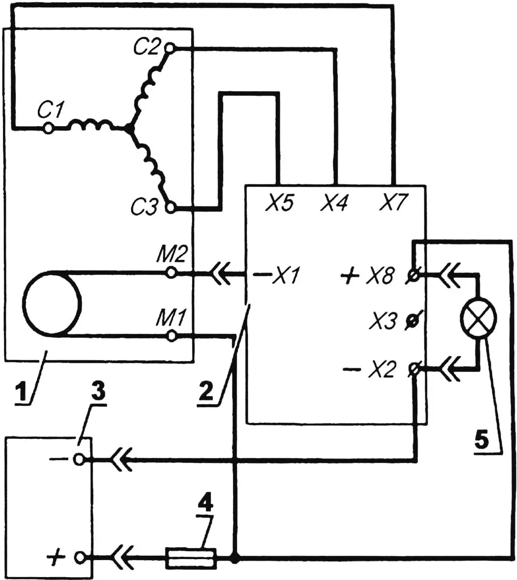
1 — automotive generator type G-221; 2 — electronic rectifier-regulator type BPV-14-10; 3 — battery (12 V and 50…60 A·h); 4 — fuse; 5 — consumers.
C1, C2 and C3 — phases of the generator stator winding; M1 and M2 — generator excitation winding; -X1 — “minus” of the excitation winding; -X2 — “minus” of the battery; X3 — positive terminal to the control lamp; X4, X5 and X7 — phases of the generator stator winding; +X8 — “plus” of the battery
The electronic block rectifier-stabilizer BPV-14-10 (such as used on Izh motorcycles and some cars) rectifies the alternating three-phase current produced by the generator, and also stabilizes the voltage at a current of up to 10 A. In addition, the block provides battery charging and switching consumers from battery power to generator power and vice versa when the latter’s rotation speed or load power changes. The rectifier-stabilizer is mounted on the frame next to the generator.
Of course, one can equip the wind power installation with another electronic block that converts direct current to alternating current with a voltage of 220 V, however, the efficiency of such a device is not too great, and this will be another source of losses in the energy conversion chain.
The transmission of electrical energy from the rectifier-stabilizer to the battery installed under the wind generator mast is carried out using the simplest collector, consisting of a pair of rings on the mast’s swivel device and a pair of contact brushes. Of course, the “positive” ring of the collector and the corresponding contact brush must be reliably isolated from the “ground”. To prevent moisture ingress, the collector is covered with a plastic “umbrella”.
In addition to a welded mast, a wooden or reinforced concrete pole, similar to those used for power lines, can serve as the support of the wind power station. If a pole is chosen as the support, it must be secured with at least three guy wires made of steel cable or wire.
1 — wind electric generator support; 2 — support plate (steel sheet 5 mm thick); 3 — collector brush post (steel channel section 30×50 mm); 4 — stationary post of the swivel device (steel pipe Ø40 mm); 5 — movable post of the swivel device (steel pipe Ø50 mm); 6 — limiting washer (fluoroplastic or nylon); 7 — support heel; 8 — ball joint; 9 — reinforcing gusset; 10 — docking platform (steel sheet 5 mm thick); 11 — insulating bushing of the collector ring; 12 — bolt with nut, washer and insulator bushing; 13 — collector ring; 14 — tension spring; 15 — collector device brush; 16 — insulating gasket
It should be taken into account that the installation height of the wind wheel depends on the presence of obstacles (trees, buildings and other structures) located in close proximity to it. In an ideal case, the wind wheel blade should be at least two meters higher than a closely located obstacle. It must be taken into account that the influence of an obstacle on the air flow extends to a distance equal to fifteen times its height.
A wind power station with a horizontal axis of rotation, despite a fairly high efficiency, has its drawbacks. In particular, the transmission of large current through the collector causes noticeable energy losses and can lead to troubles both due to contact failure when they oxidize and due to a decrease in the elasticity of the brush device plates. And one more thing: a wind wheel of this type has the qualities of a gyroscope — a top striving to maintain the orientation of the rotation axis in space. That is why, when the wind direction changes, a significant load arises on the bearings, which shortens their service life.
“Rotor”
In many cases, a rotor WPS will be more advantageous, in which the wind wheel has a vertical axis of rotation and can work in any wind direction.
Several types of rotor wind engines are known. One of the simplest and most effective is a wing rotor, representing a hollow cylinder cut along a diametrical plane with parts shifted relative to each other. Such a rotor, although slower than a wind wheel, has greater torque and is capable of working at low wind speeds. Its main advantage is the ability to rotate in any wind direction and, as a consequence, the absence of a swivel device and collector.
The simplicity of its design is also among the advantages of a WPS with a wing rotor.
The rotor wind generator is mounted on a pole or mast. How this is done is already known to readers from the description of the “Disk” type WPS. The base is welded from steel angles with a cross-section of 4x40x40 mm. A stepped shaft is welded to its upper part, on which a brake drum from a Ural or Izh motorcycle wheel is installed.
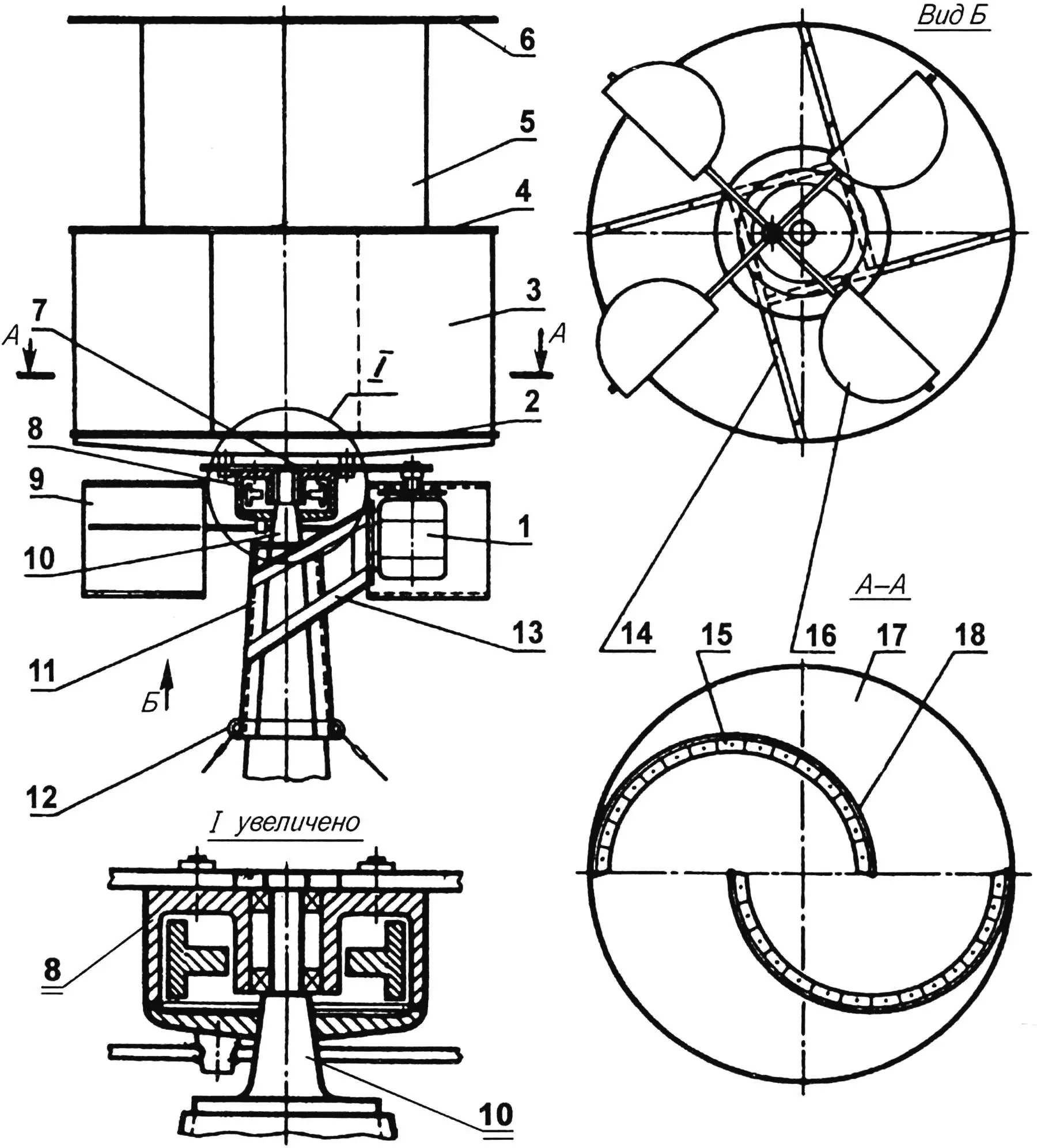
1 — electric generator type G-221; 2,4,6,17 — aerodynamic washers of the rotor wind wheel; 3,5,18 — rotor blades; 7 — chain drive of the multiplier; 8 — wind wheel hub (motorcycle brake drum); 9,16 — aerodynamic brake device blades; 10 — rotor wind wheel rotation axis; 11 — support; 12 — guy wire attachment lugs; 13 — electric generator mounting bracket; 14 — lower aerodynamic washer reinforcement (wooden block 40×40 mm); 15 — bracket (angle 30x30x2 mm, duralumin)
The rotor is made from plywood. Three disks with a diameter of 1000 mm and a thickness of 10 mm will be required — for aerodynamic partition washers and four plates with dimensions of 500x 1050 mm and a thickness of 4…5 mm — for rotor blades. The joining of all these elements is done using duralumin angles with a cross-section of 30x30x2 mm, bent as shown in the drawings, and M5 screws with nuts and washers. The rotor is reinforced with ties made of steel rods with a diameter of 6 mm with threads on the ends. The lower washer is reinforced with wooden blocks with a cross-section of 40×40 mm.
After preliminary assembly, the rotor is disassembled, the plywood elements are impregnated two to three times with hot linseed oil, after which it is assembled finally and painted with alkyd enamel.
The rotor is mounted on the bearing unit (brake drum from a motorcycle) using spacer bushings and M8 bolts with nuts and washers. A homemade driving sprocket of the chain multiplier is installed between the unit and the rotor, and a driven one (small sprocket from a D8 or V-50 engine) is installed on the generator shaft. The driving sprocket is cut from a duralumin sheet 4 mm thick using a known technology, when centers of holes forming tooth depressions are first marked on its pitch circle, and then the teeth themselves are formed using a drill, hacksaw and files. The multiplier gear ratio I = 5…6.
The automotive generator is installed on a bracket that, together with the wing rotor base, forms a single welded unit. The generator mounting to the bracket is standard, as on a car: using a hinge and a threaded lock-tensioner.
The rotor wind generator is equipped with almost the same brake device as on the “Disk” type WPS. Its drive is also aerodynamic: a steel bushing with four welded tubular rods is fixed on the brake cam axis. Semi-cylindrical plywood blades are located at the ends of each. The spring that tightens the brake pads is replaced with another one with lower stiffness. Such a device should activate at a wind speed above 10 m/s.
The electronic circuit of the rotor WPS is no different from that used on the “Disk” wind generator.
Recommend to read
 THE “HOOK” OF THE PAINTER
You paint the fence for the first time or renews oblasti — in any case, the work is time-consuming in itself, but still every time you bend with a brush or roller to the container of... THE DRAFT IS NOT TERRIBLE
With insulation front door difficult to close up a crack from the attachment loops. However, there is a simple way to prevent the flow of air between the door and the frame: simply stick...
