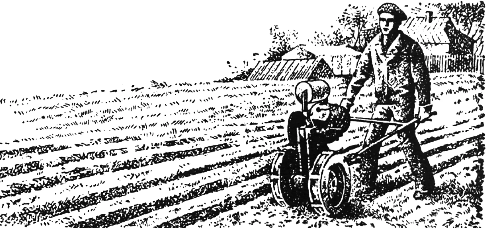
Of the family of micro-tractors developed by students at the Kharkiv Institute of Mechanization and Electrification of Agriculture, the simplest and most accessible for DIY construction is the walk-behind tractor “Malysh” (KHIMESKh-2): it makes maximum use of units and parts from industrially produced machinery.
This is a compact two-wheeled machine controlled by an operator walking behind it. A large set of interchangeable trailed and mounted implements makes the walk-behind tractor versatile, allowing it to be used for plowing, harrowing, cultivation, hilling, and other soil tillage and crop care operations, and when coupled with a single-axle trailer — also as a transport vehicle for various household loads.
In the latter case, the operator becomes the driver and sits on a sprung seat at the front of the trailer.
Thanks to these properties, the walk-behind tractor can be used not only on a private farm, but also to mechanize labor-intensive processes in crop production, especially in vegetable growing and on experimental plots of breeding stations, as well as in livestock farming and greenhouse operations.
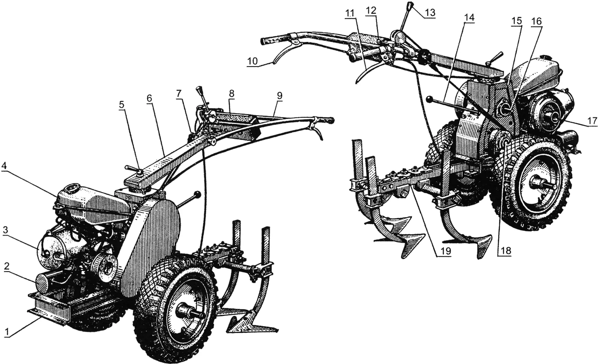
1 — frame; 2 — muffler; 3 — engine; 4 — fuel tank; 5 — traverse lock; 6 — traverse; 7 — control linkage lock; 8 — tool bag; 9 — crossbar of the control linkage; 10 — clutch lever; 11 — wheel lock lever; 12 — throttle lever; 13 — gearshift lever; 14 — differential reverse lever; 15 — transmission housing; 16 — power take-off shaft; 17 — starter pulley; 18 — final drive shaft; 19 — mounted implement (cultivator)
The main units of the “Malysh” design are the VP-150M engine, transmission, power take-off system, running gear, control system, and hitch device, arranged on a rectangular channel frame.
Of the engines produced by industry for privately owned machinery, the VP-150M engine from the “Elektron” motor scooter, rated at 7.5 hp (5.5 kW), proved most suitable for the walk-behind tractor. It is a single-cylinder, two-stroke, carbureted engine; it has a compact built-in gearbox and a clutch; it uses electronic ignition. Equally important is that the motor is equipped with a centrifugal fan, whereas when using other engines, amateur builders have to solve forced cooling issues in makeshift ways.
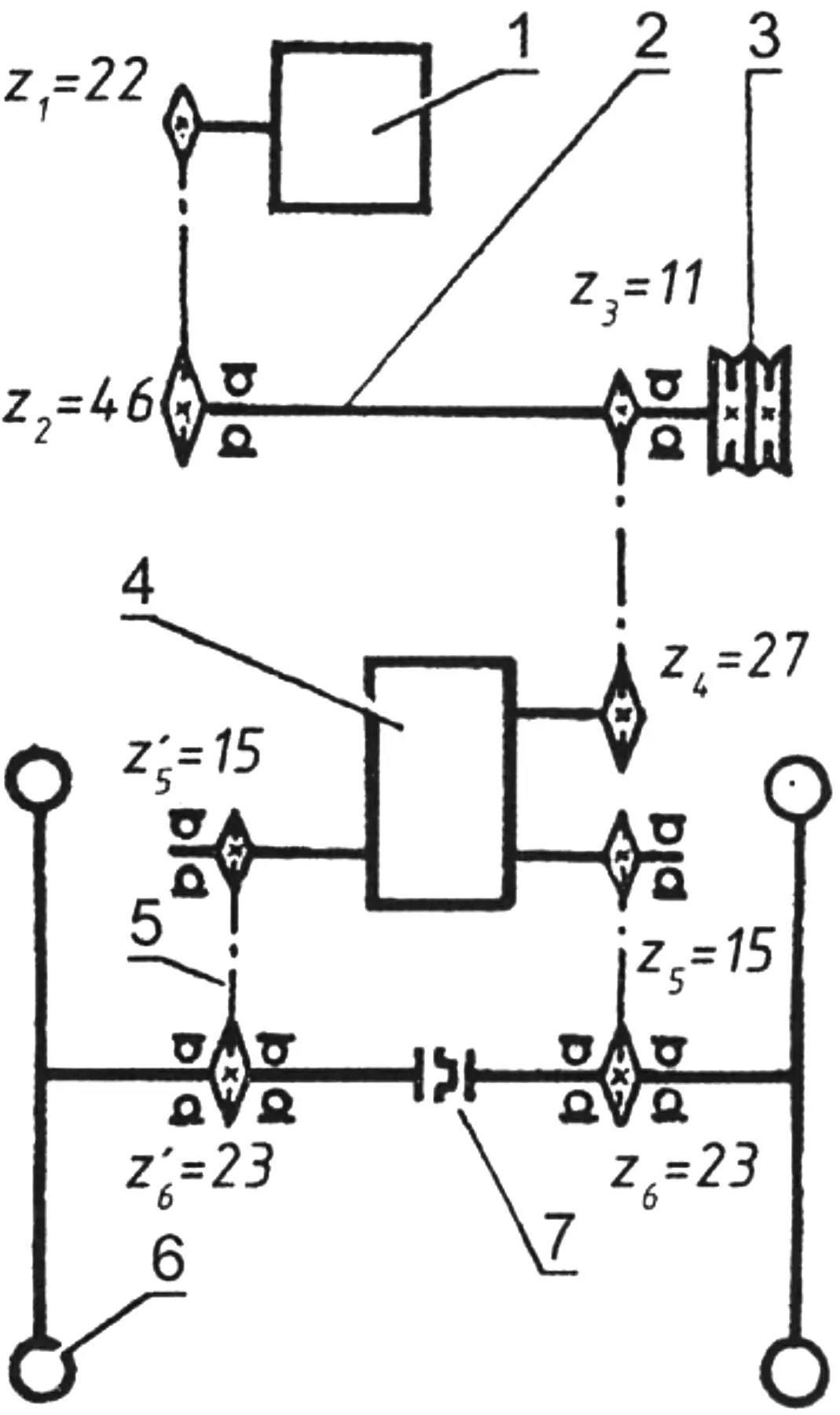
1 — engine; 2 — intermediate shaft; 3 — two-groove power take-off pulley; 4 — differential; 5 — final drive; 6 — wheel; 7 — wheel lock mechanism
In case other motors are used, we provide the main data on the VP-150M engine for comparison. Torque is transmitted to the gearbox by a helical gear pair with a ratio of 3.045. The gearbox itself is three-speed, with constantly meshed gears. Gear ratios by stage: first gear — 4.883, second — 2.888, third — 1.800. Since the engine and gearbox are made as a single monoblock, their description is not given here. There are also no special requirements for operating and servicing the engine together with the clutch and gearbox: these are governed by the manufacturer’s recommendations.
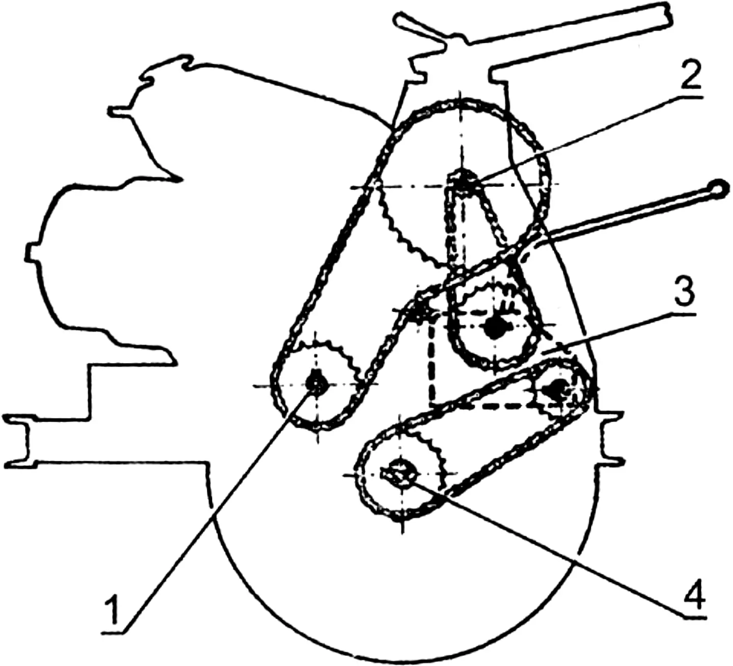
1 — engine output shaft; 2 — intermediate shaft; 3 — differential; 4 — wheel half-axle
The walk-behind tractor transmission is mechanical, gear-and-chain. It consists of a series differential with reverse (from the “Muravey” cargo motor scooter), an intermediate shaft, two final drives, and a wheel lock mechanism. The intermediate shaft also serves to take off power for mounted implements.
Torque is transmitted from the engine to the intermediate shaft by a chain with a pitch of 12.75 mm; from it to the differential — by a chain with a pitch of 15.875 mm, and then again by final-drive chains with a pitch of 15.875 mm — to the drive wheels. Sprocket Z1 comes from the engine, Z4 is included in the differential set, and Z2 and Z3 are taken from the “Voskhod” motorcycle.
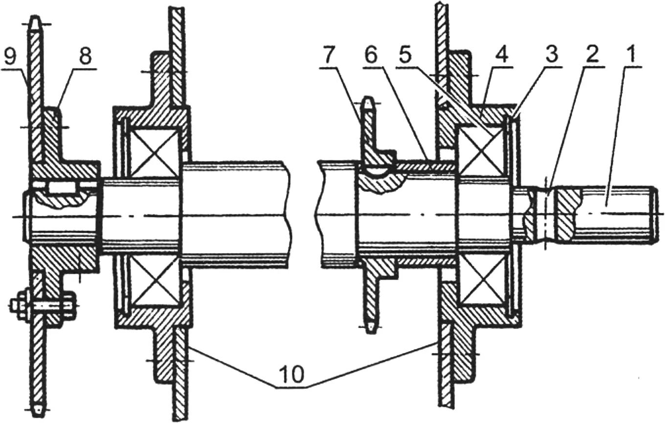
1 — shaft; 2 — pulley seating area; 3 — retaining ring; 4 — bearing housing; 5 — bearing No. 180205; 6 — spacer bushing; 7 — sprocket Z3; 8 — flange; 9 — sprocket Z2; 10 — housing
The intermediate shaft is made of steel 40 and mounted in two ball bearings No. 180205. Flanged housings for them can be taken from scrapped agricultural machines; they are fastened to the side cheeks of the transmission housing. The seating diameters of the shaft are chosen according to the sprocket hub sizes, and the length — depending on the width of the transmission housing plus some allowance so that a two-groove drive pulley 100—120 mm in diameter can be installed on the right side.
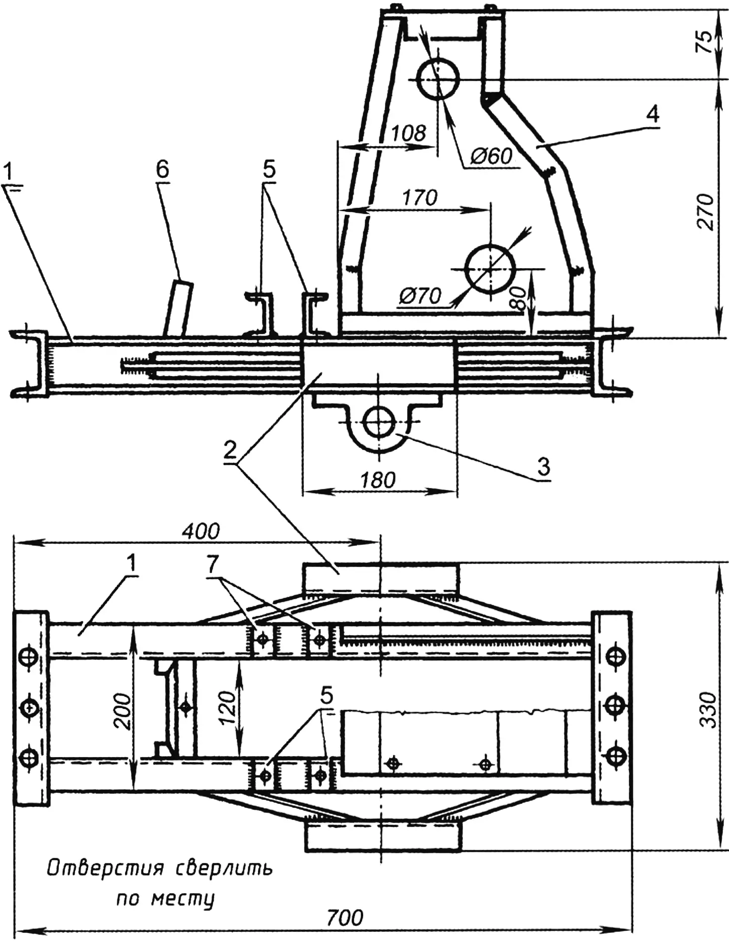
1 — side members; 2 — half-axle brackets; 3 — half-axle bearing housing; 4 — transmission housing (in the top view, its right half is not shown); 5 — brackets for mounting the engine output shaft journal; 6 — front engine support; 7 — kick-starter journal mounting brackets
The walk-behind tractor frame is welded from suitable profiles available on hand; in the “Malysh”, channel No. 6 is used for its longitudinal side members, and No. 8 for the cross members. From below, half-axle bearing housings are bolted to the horizontal frame side members and to the brackets. Bearings No. 180207 are installed here — two per half-axle; their housings are also best taken from scrapped agricultural machines. Mounting them on the brackets must be done especially carefully: wheel coaxiality and perpendicularity of the half-axles relative to the longitudinal frame axis should be maintained as accurately as possible. To mark holes for fastening the housings with bearings, they are mounted on a solid mandrel shaft, which should later be cut into two half-axles. The indicator of correct housing installation is free rotation of the mandrel in the half-axle bearings.
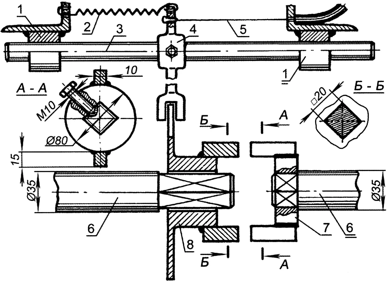
1 — guide bushings; 2 — return spring; 3 — slider; 4 — fork; 5 — cable; 6 — half-axles; 7 — fixed half-clutch; 8 — movable half-clutch
Then angle bars 25×25 mm are welded to the rear part of the frame, and the transmission housing made of 5—6 mm steel sheet is bolted to them. It serves as the base for installing the intermediate shaft, differential, and control mechanism. The rear side of the housing has a removable cover; the front side has a bracket for mounting the fuel tank.
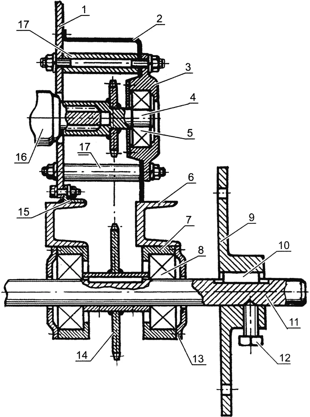
1 — transmission housing; 2 — final drive housing; 3 — bearing housing; 4 — drive shaft with sprocket Z5; 5 — bearing No. 180205; 6 — channel No. 6; 7 — bearing housing; 8 — bearing No. 180207; 9 — wheel hub; 10 — key; 11 — half-axle; 12 — hub retaining bolt; 13 — bearing cover; 14 — sprocket Z6; 15 — angle bar 25×25 mm; 16 — differential; 17 — spacer bushing
In the front part of the frame, angle bars are welded inside — a bracket for the engine with a forced-cooling fan.
The axle (or half-axles) is made of quality steel; its dimensions may be refined depending on the available bearings and wheel hub sizes. Two half-clutches are mounted on the inner side of the half-axle. The right one moves freely on a square section and, by means of a lever mounted on the control rod, engages with the left half-clutch, providing a rigid connection of the half-axles — wheel lock.
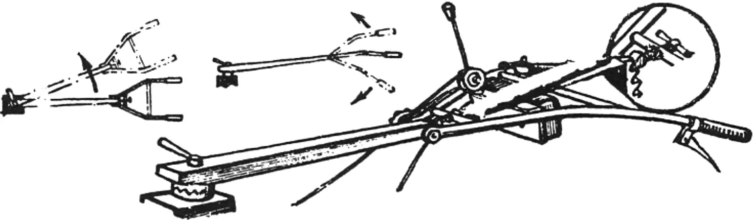
The design of the controls is clear from the drawings. The handle rods are connected to the traverse by a clamp hinge, which allows adjusting the handle height to suit the operator’s stature. In addition, the traverse itself can be rotated 180° or to any required intermediate angle, which provides additional convenience when operating the walk-behind tractor.
«Modelist-Konstruktor» No. 12’2012, V. VINNIK, M. KAREVA, D. TKACHENKO, Kharkiv, Ukraine
Recommend to read
 AND AEROASTRO
Snowmobile Ka-30. The first test of the snowmobile "North-2", created in OKB famous designer of helicopters, N.And.Kamov, showed that they have two fatal defect is small capacity and... ALMOST NAKED GAULS
France withdrew from the First world war among the winners, but the state of Affairs she was far from rosy. The country suffered huge human and material losses, the civilian economy was...
