 After our magazine began to publish materials about motonartah, created by enthusiasts of technical creativity, the number of such vehicles built by Amateurs has increased dramatically. Many of them according to their operating characteristics, reliability and original design solutions of individual units are not inferior to motoneta by the industry. It fans belongs priority in the use of metal tracks instead of rubber, which become unusable at low temperatures; it has conducted a number of experiments with different wheels (spiked wheels, screws, conical paddle wheels, multi-tracks, etc.).
Naturally, in the avant-garde artists, designed the first in our country motonarty, people were quite experienced — drivers, mechanics, motormen, They quickly figured out the intricacies of new technology, skillfully applied serial parts, components and mechanisms, and achieved good results. However, the vast majority of hobbyists are outfitting their motonarty relatively powerful motor and motorolleri engines, they are labor intensive to manufacture and require considerable material costs. Taken together, this inhibits the development and wide dissemination of technical motoart in children’s clubs, Houses of pioneers and schoolchildren. And it is clear to everyone that motonarty have the right to occupy in the lives of our younger generation of young technicians the same place which has long and firmly holds the kart. However, inexpensive, simple and easy design motoart had not been established.
But here, the editors received a letter from the village Tolbukhin in the Yaroslavl region of the pupil of the 10th class Sasha Gromov. It was neatly made drawings and photographs of the original motoart equipped… bike motor D-5! “Porn” is an affectionate name coined for Sasha Gromov. Here is what he wrote:
“I just didn’t have another engine. I decided to try if I can motonarty to move vasomotorial capacity of only 1.2 HP And set to work. Great assistance was rendered me the journal publishes materials on all-terrain technology.

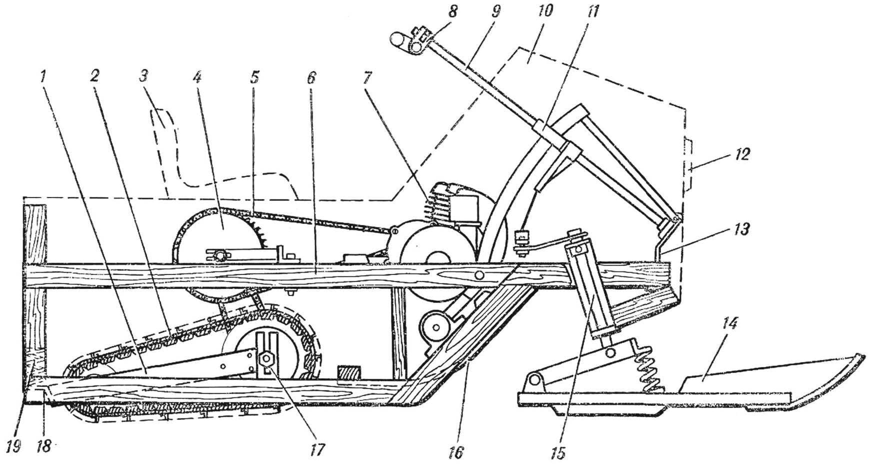
Fig. 1. The overall layout micromotors “porn”:
1 — the carriage of the track 2 mite caterpillars, 3 — driver seat, 4 — intermediate sprocket 5 — chain engine, 6 — body frame, 7 — engine D-5, 8 — wheel, 9 — steering shaft, 10 — casing-fairing of the front part, 11 — bearing bushing steering shaft, 12 — beam, 13 — lower bearing, steering shaft, 14 — steering ski, 15 — front steering skis 16 — plate 17 — a tensioning device for the leading chain, 18 — foot square, 19 — spring
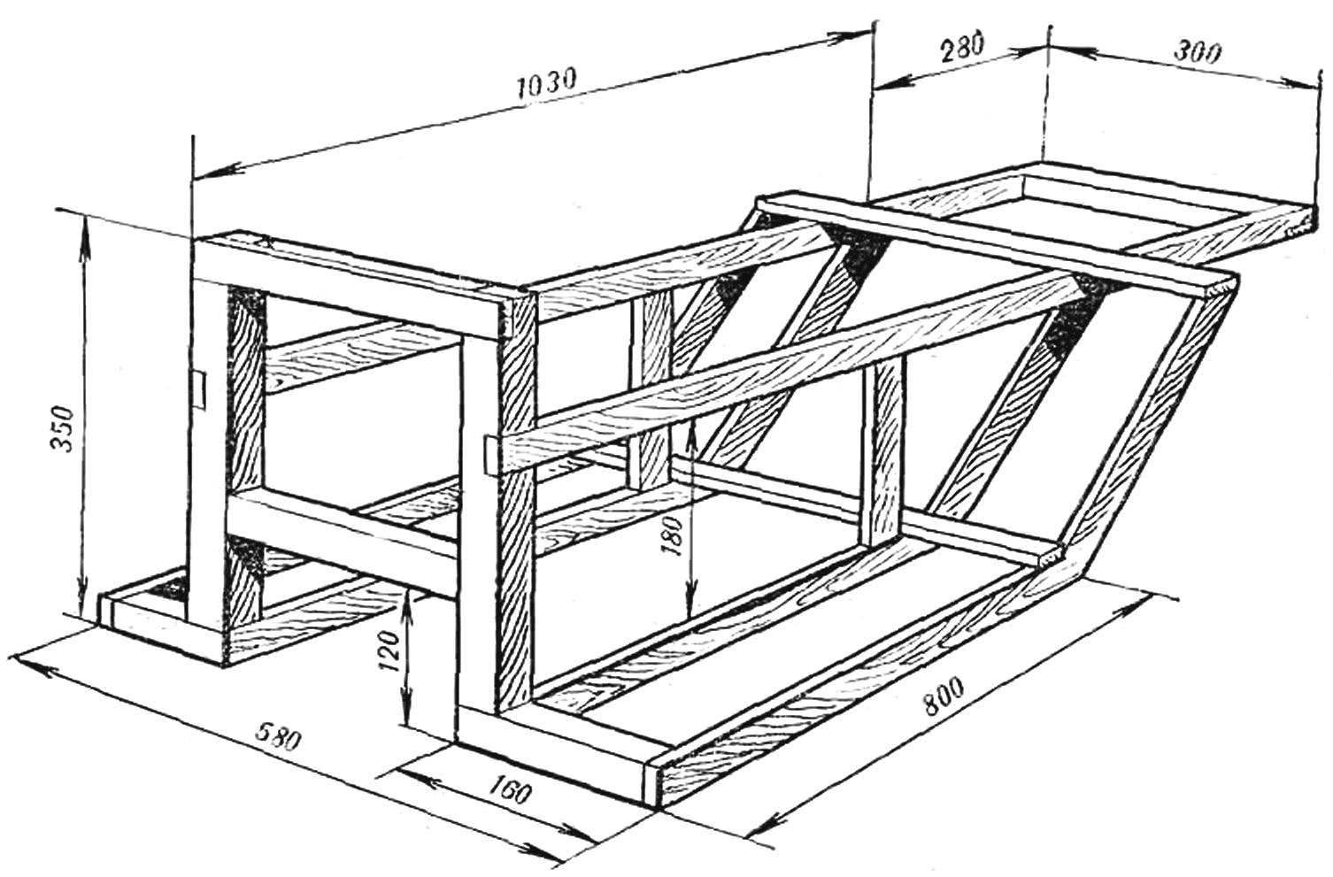
Fig. 2. The design of the frame housing micromotor.
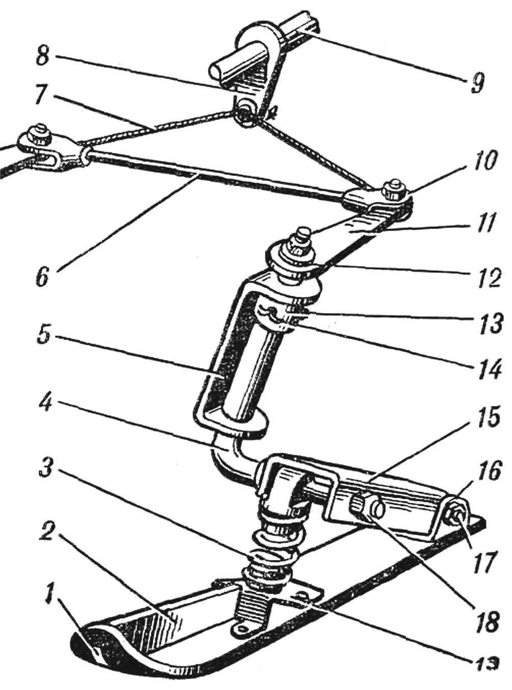
Fig. 3. The steering skis and its suspension:
1 — ski, 2 — rib, 3 — spring, 4 — axle, 5 — bracket, 6 — rod, 7 — bridle of rope Ø 5 mm, 8 — hog steering column, 9 — steering shaft, 10 — forked tip of the transverse thrust, the 11 swing arm 12 — crown to axle, 13 — thrust washer, 14 — pin, 15 — a swinging arm, 16 — clip rocker arm, 17 — axis, 18 — nut, 19 — the emphasis of the spring.
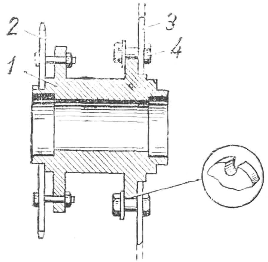
Fig. 4. Intermediate shaft:
1 — body bushings, 2 — small star, 3 — big star 4 — bolt.
Like any design (especially the first), my “porn”, of course, has many disadvantages. But he is moving! He has a right to exist! And the next phase — to improve my car.”
We became acquainted with the sent to Sasha Gromov material on micromechanical “porn”. This machine, of course, far from perfect, but is of interest for a wide range of young readers of our magazine due to the simple design and the availability of used parts and materials,
Malyshok (Fig. 1) built on a widespread scheme, with one leading track, and two front steering skis. Here is its brief description.
The frame body Motonari (Fig. 2) made of pine bars section 20X40 mm, assembled on epoxy glue, using plywood gussets and reinforcing plates. In the front on the bottom a metal plate with a thickness of 0.8 m, the snow in front of the sealing rubber tracked tape. The hull is sheathed with plywood, 3 mm thick epoxy resin. For mounting the engine, transmission, controls, provides metal brackets attached to the bars of the frame with bolts and washers of large diameter, to prevent crushing of the wood. In the front of the housing on the brackets placed axle mounting steering skis. They are free to rotate in the brackets and are held from vertical displacement of the thrust rings. The rotation of the axles is accomplished through a lever fitted on the square at the top of the axle. Managed ski Bicycle wheel, through the steering column, fry and rope. Steering levers left and right skis connected by a tie bar (Fig. 3).
Skis made of wood. Socks they have the duralumin fittings. On the soles of the skis installed undercuts that improves the stability of the course and to facilitate the control. Ski suspension linkage, spring-loaded, relatively simple in design and well softens the bumps on rough roads.
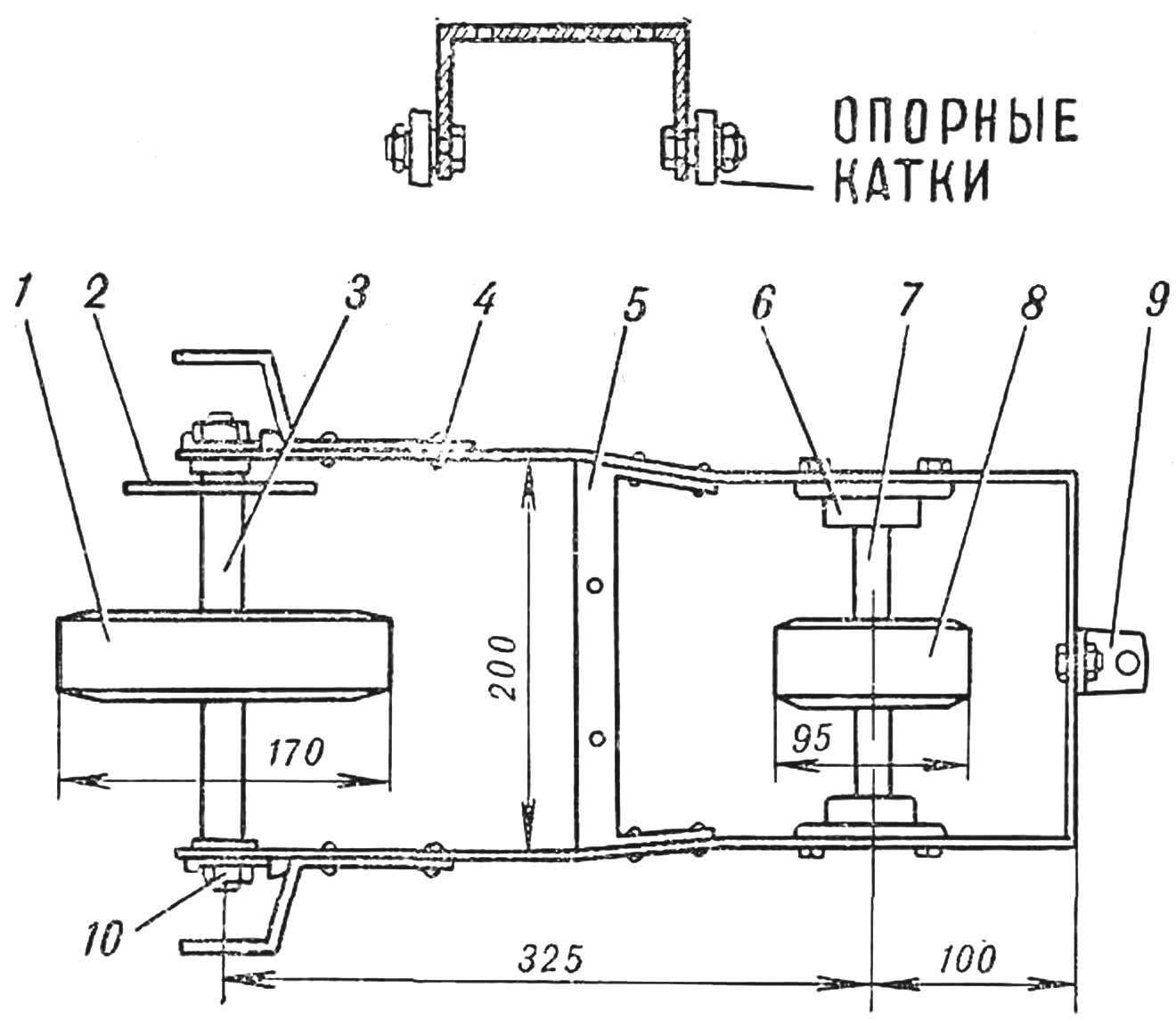
Fig. 5. The power of the caterpillar, the view from below:
1 — drive pulley 2 — drive sprocket, 3 — drive shaft pulley, 4 — frame, carriage, 5 — cross member of the carriage, 6 — bearings of the driven pulley 7 to the shaft of the driven pulley 8 is driven pulley, 9 — bracket-support springs 10 — bearing drive shaft.
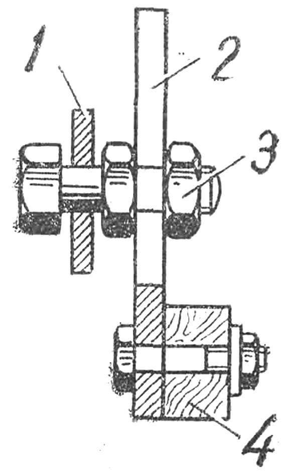
Fig. 6. The clamping of the carriage (figure 1 number 17):
1 — carriage, 2 — strut, 3 — bolt, 4 — bar frame.
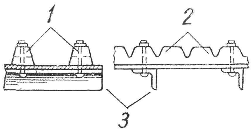
Fig. 7. Track (rear and side views):
1, 2 — V-belts, 3 — lugs.
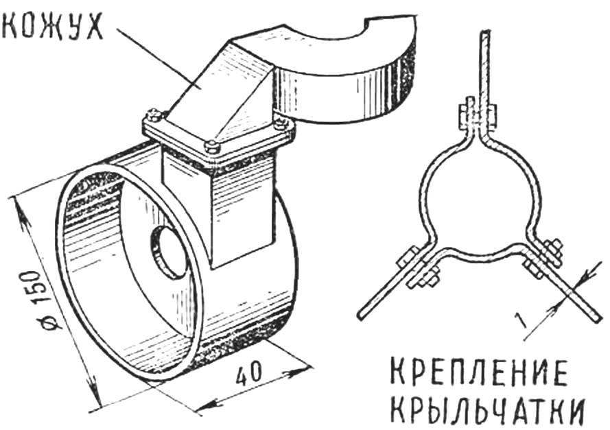
Fig. 8. The design of the engine cooling fan.
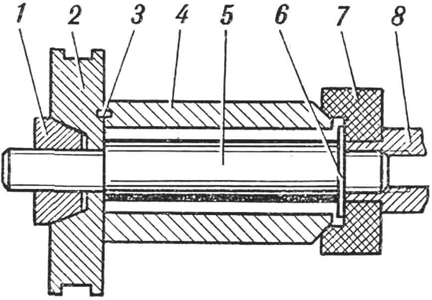
Fig. 9. Install the starter pulley on the end of crankshaft:
1 — cone nut, 2 — wheel, 3 — stud, 4 — bushing, 5 — axis, 6 — washer 7 — nut 8 — the neck of the crankshaft.
Transmission motoart consists of a motor chain connecting the sprocket engine countershaft, and driving chain connecting the intermediate shaft with the driven sprocket on the shaft track. The shaft is mounted in a U-shaped bracket mounted on the transverse angle of the chassis frame. Clip allows you to carry out the movement for chain tension. The intermediate shaft is made of a sleeve of the front wheel of the motorbike, with the installation of its flanges veins (Fig. 4). A small asterisk is borrowed from the rear wheel of the bike and has 19 teeth. This sprocket shaft track. 3 sprocket with 41 tooth, taken from the leading wheel of the motorbike. It is secured by three lugs in the slots, progressirovanii on the sleeve, and is tightened with bolts. It is a chain from the engine. Bushing with the sprocket is free to rotate on the axis of the intermediate shaft, which is mounted on two bearings No. 200. From the drive sprocket chain is driven sprockets drive the track. Crawler mechanism consists of the carriage (frame), front and rear axles with pulleys and rollers. The slide is made of flat steel 40X6 mm, with a jumper from the corner 25X25 mm. drive shaft track 3 (Fig. 5) welded thereto a pulley rotates in sliding bearings 10 that are planted on the Cams, serving to tension the track. Driven shaft 7 welded thereto a pulley 8 is mounted on two ball bearings No. 200 mounted in the clips. Driving and driven pulleys of metal, planted them with rubber bands. The carriage track is attached to the body motoart articulated through the plate (see Fig. 1), which has a vertical slot for axial bolt after adjusting the position of the carriage, fixed by the nut (see Fig. 6).
At the rear (in the direction of the machine) of the carriage (Fig. 1) placed the angle bracket 18, which rests on a spring 19, the cushioning the carriage and is constantly pressed against the snow surface when the crawler belt, which is made from old conveyor belts of a thickness of 3 and a width of 150 mm. From the inner side to her two riveted V-belt (Fig. 7). The distance between them provides a wedging them on the master and slave pulleys. Due to the resulting friction force is the movement of the tape. Simultaneously, wedge-shaped straps keep it from slipping off the pulleys to the sides. For greater elasticity of the V-belts on the inner part has notches (teeth) to half their thickness. On the outer side of the tape on the rivets with a pitch of 65 mm are fixed lugs 17 of the angled steel 20X20 mm.
Motor installation Nart Malyshok — waldwichtel D-5, equipped with forced cooling system from a simple fan (Fig. 8), which consists of an impeller mounted on the end of the crankshaft and the housing, directing the airflow to the edges of the cylinder. Cover prikladyvaya on the right side of the engine on the clutch cover. Engine starting cord is spooled on a special skivor. For its mounting on the end face of the crankshaft mounting screw gear is replaced with the axis 5 with washer (Fig. 9). Axle fits over the sleeve 4, which conical end is centered on the bore of the gear. Sleeve 4 is tightened through the starter pulley 2 cone nut 1. From the mutual rotation of the pulley and the sleeve protects them pin 3.
The fuel supply to the carburetor by gravity from a tank placed in the front, over the steering column. The engine is a homemade silencer from a thin-walled pipe Ø 50, welded on both sides of the washers with holes for gas outlet; a Bicycle generator driven in rotation by a V-belt from the pulley on the crankshaft. The generator powers a Bicycle headlight and taillight.
The driver is placed on the cushion of sponge rubber attached on the track to the body motoart.
Snowmobile Malyshok designed by student of 10th class Sasha Gromov.
Length, mm:
overall……………………………………1700
tracks (between the axles)…………………360
steering ski………………………………….700
Width, mm: overall…………………580
caterpillar……………………………………….150
Engine………………………………………D-5
D-5, 1,2 HP at 4500 rpm
Fuel, kg……………………………4
Weight dry, kg…………………………………..35
The speed of the solid crust, km/h…….8-10
Recommend to read
 JL-8/K-8 Karakorum (China/Pakistan)
Combat training aircraft K-8 Karakorum was created in 1986 jointly by the Chinese company HAIG and Pakistani RACES. The first prototypes were assembled in 1989, the First flight took... PLOW? NO MOWING
Perhaps no one in the right mind would plant potatoes otherwise than in the ground. And complexity used in this conventional technology well known. And because of the large gardens still...
