In a homestead or dacha farm, even a small one, any mechanized cargo vehicle is a great help. It saves both time and effort. Of course, when it’s simple and reliable. It’s desirable that the machine be small in size for maneuverability and have sufficient power (even at the expense of speed). Its cross-country ability should also be excellent. Road inspection doesn’t particularly welcome the appearance of such homemade trucks on highways, so their lot is mainly dirt country roads. As a rule, such roads have two clear ruts (after all, they’re not even profiled), so movement on them by three-wheeled vehicles (“ants”, walk-behind tractors with trailers — the most accessible for most owners) is difficult.
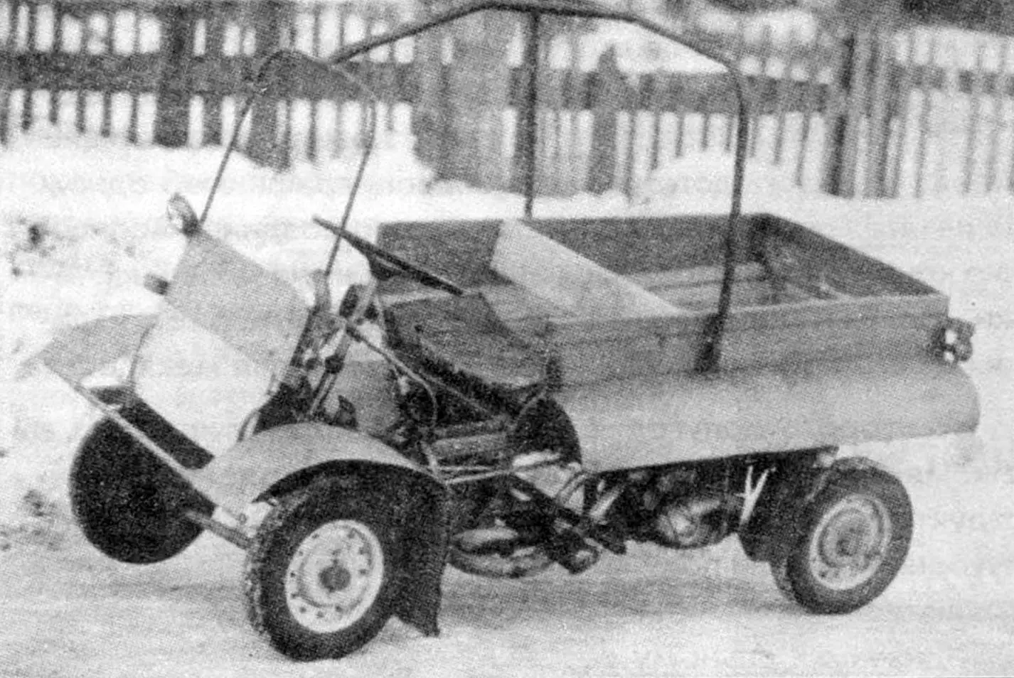
The listed circumstances suggested to me that I needed to design a simple four-wheeled truck (more precisely, a self-propelled cart) with a motorcycle engine, which was done practically from those materials, parts, and units that were at hand.
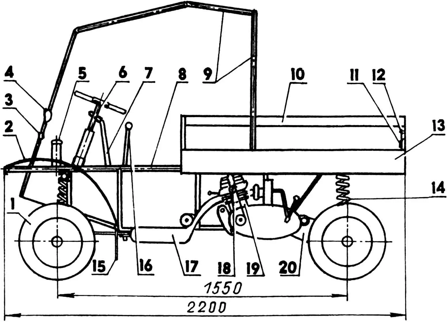
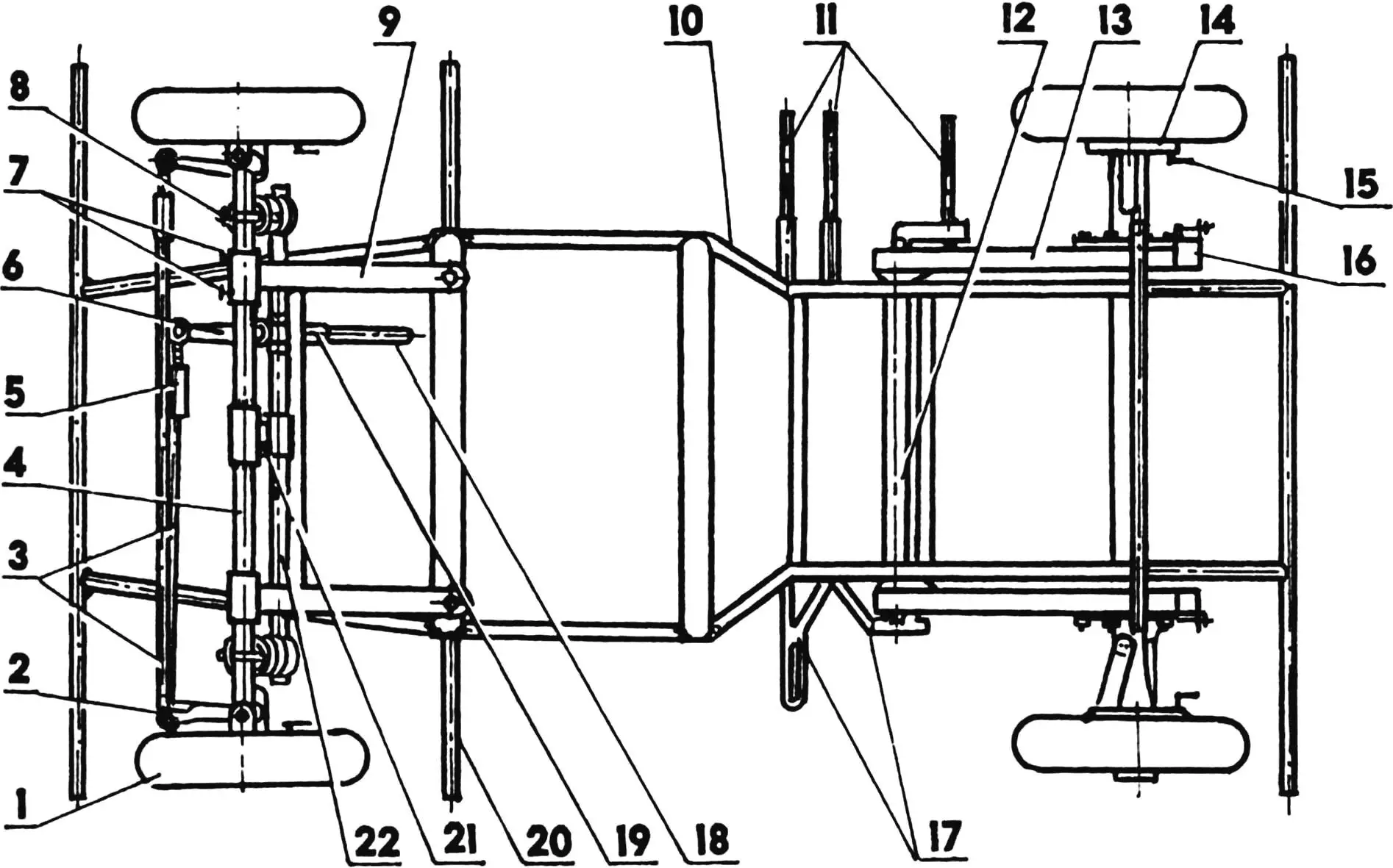
1 — wheel (4 pcs.);
2 — front fender (tin, s0.5; 2 pcs.);
3 — front turn indicator (2 pcs.);
4 — headlight (2 pcs.);
5 — shock absorber;
6 — steering wheel;
7 — parking brake lever;
8 — frame structure;
9 — safety arches;
10 — body;
11 — stop light (2 pcs.);
12 — rear turn indicator (2 pcs.);
13 — rear fender (tin, s0.5; 2 pcs.);
14 — front and rear suspension springs (4 pcs.);
15 — mudguard (rubber, 2 pcs.);
16 — gear shift lever;
17 — muffler;
18 — engine forced cooling fan;
19 — engine (from “Kovrovets” motorcycle);
20 — rear suspension pendulum arm (2 pcs.);
21 — steering knuckle;
22 — front axle beam;
23 — fairing (tin, s0.5);
24 — steering rods;
25 — front axle beam suspension console (2 pcs.).
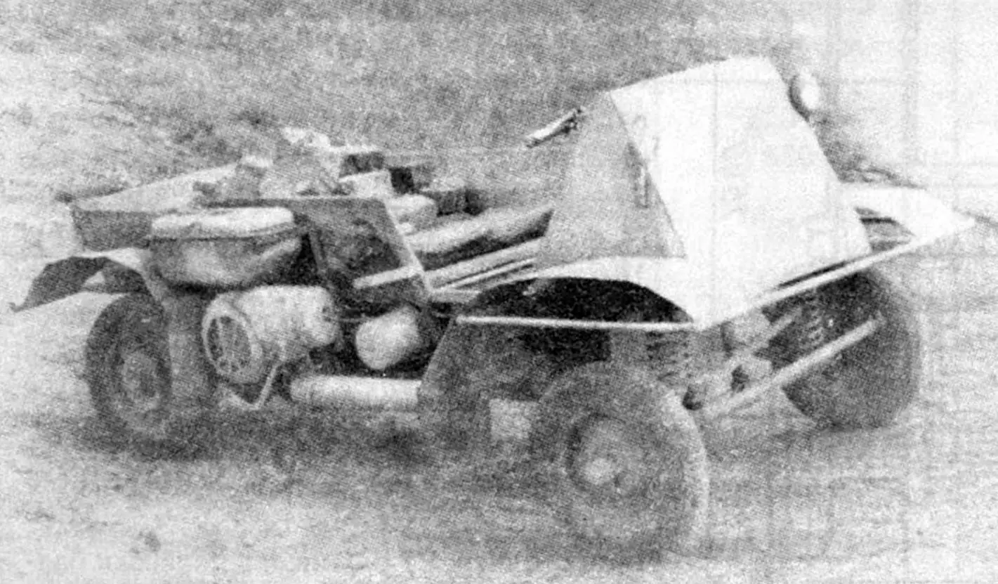
This motorized helper with a VP-150M engine from the “Vyatka” motor scooter proved itself quite well, and over time, following its pattern and likeness, with some improvements, I made another similar machine with an engine from the “Kovrovets” motorcycle. The machines replace each other when one of them is under maintenance or repair. But I use the second one more often in summer, since it currently has only one rear drive wheel. The first one, with both rear drive wheels (like a racing kart), — in winter, and in summer — in bad weather. There’s no differential between the drive wheels yet, but I’ve already thought through its design and even made its sketches. It will be a not quite ordinary side differential on the drive (extended output) shaft of the cart’s engine. If the tests are successful, I’ll definitely share the development with the readers of “Modelist-Konstruktor”. But we’ll talk about suspensions later.
| With engine from VP-150M motor scooter | With engine from “Kovrovets” motorcycle | |
|---|---|---|
| Weight, kg | 235 | 220 |
| Wheelbase, mm | 1500 | 1550 |
| Front wheel track, mm | 1100 | 1100 |
| Rear wheel track, mm | 1050 | 1050 |
| Payload, kg | 150 | 200 |
| Maximum speed, km/h | 37 | 45 |
| Power, hp | 7 | 9 |
| Engine location | right | left |
| Brake wheels | rear | all |
| Turning radius, m | 3 | 3.5 |
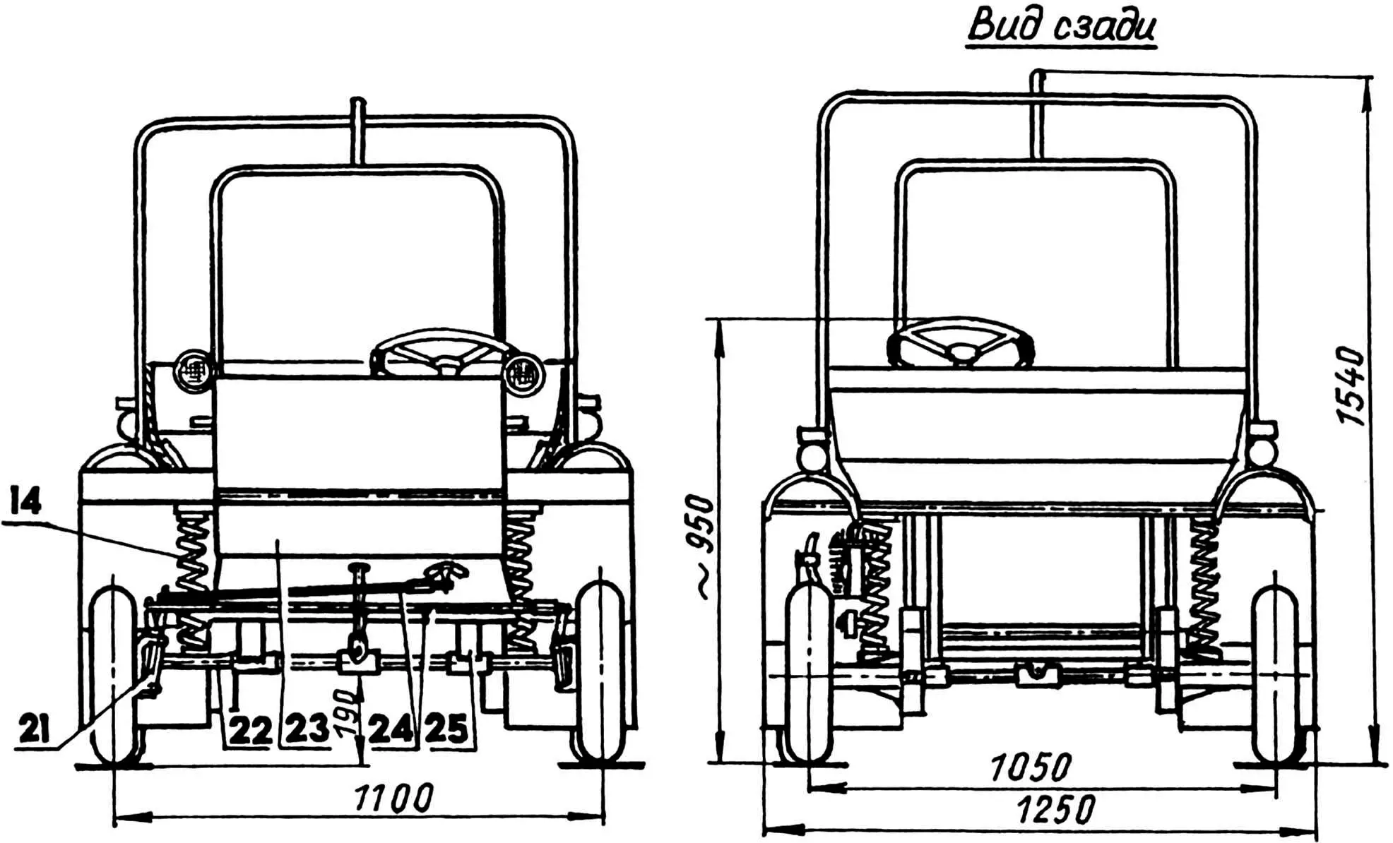
The load-bearing frame of my “tetracycle” is a spatial steel truss, welded from two frames, united by five pairs of posts and three pairs of braces. The side members and cross members of the upper frame are made from a 27 mm diameter tube with a 2 mm wall thickness. Instead of the outer cross members, crossbeams made of 33.5 mm diameter tubes with a 3.2 mm wall thickness are welded to the frame, which serve as supports for the upper ends of the cart’s suspension springs. A shock absorber cylinder mounting bracket and steering shaft column are mounted on the front crossbeam.
1 — front bumper;
2 — upper side member (2 pcs.);
3 — front crossbeam (steel tube 33.5×3.2);
4 — shock absorber mounting bracket (steel tube 40×3);
5 — fender mounting bracket (2 pcs.);
6 — interframe post (8 pcs.);
7 — upper long cross member;
8 — VP-150M engine mounting bracket;
9 — pendulum arm and drive shaft axis supports;
10 — upper short cross member (2 pcs.);
11 — gusset (2 pcs.);
12 — rear crossbeam (steel tube 33.5×3.2);
13 — rear bumper;
14 — brace (steel rod Ø9.6, 6 pcs.);
15 — lower short cross member (4 pcs.);
16 — side member reinforcement (steel angle 25×25, 2 pcs.);
17 — engine mounting brackets from “Kovrovets” (“Voskhod”) motorcycle;
18 — muffler mounting bracket (2 pcs.);
19 — lower long cross members (leaf spring 45×5 from “Pobeda” car);
20 — lower frame side member (steel angle 25×25, 2 pcs.);
21 — front suspension consoles;
22 — front axle beam mounting bushing (2 pcs.);
23 — front interframe post (2 pcs.);
24 — steering column (steel tube 33.5×3.2).
Manufacturing materials of elements:
Parts No. 1, 2, 5, 7, 10, 13, 18 are made from steel tube 27×2.5.
Parts No. 6, 15, 23 — from rectangular steel tube 25×20×2.5.
The side members of the lower frame are made from 25×25 mm angle with additional reinforcement from below in the engine section with overlays of the same profile. The cross members of this frame in the driver’s section are made from a leaf spring with a cross-section of 34×5 mm from the “Pobeda” car: a floor made of 1 mm thick steel sheet is laid and welded on them. In addition, front suspension consoles made from the same leaf spring strips are attached to the front cross member. The remaining cross members of the lower frame are made, like the posts, from rectangular tubes with a cross-section of 25x20x2.5 mm. The braces between the frames and posts are made from 9 mm diameter rod.
Engine and transmission mounting parts are welded to the lower frame side members, posts, and cross members in its engine section: brackets, supports, gussets. The load-bearing frames of both carts are practically identical and differ only in the shape, number, and installation location of brackets for mounting the power unit and transmission.
The 30 mm diameter front axle beam of the first cart is made from a cut-off steering shaft of a cargo truck, while the other one is made from two tubes of hydraulic cylinders from the front fork of an old “Voskhod” motorcycle, joined coaxially end-to-end in the middle and welded around the circumference. A bandage tube section is fitted and welded onto it at this location.
1 — wheel (from SZD motorized wheelchair, 4 pcs); 2 — steering knuckle arm (bicycle crank, 2 pcs); 3 — short and long steering rods; 4 — axle beam (from cargo truck steering shaft and “Voskhod” motorcycle front fork hydraulic cylinders); 5 — steering rod adjustment coupling (2 pcs); 6 — steering arm; 7 — beam fixators (M8 screw, 4 pcs); 8 — suspension spring (4 pcs); 9 — front suspension console (leaf spring from ZIL-130 truck, 2 pcs); 10 — power frame (upper and lower frames); 11 — engine mounting brackets from “Kovrovets” (“Voskhod”) motorcycle; 12 — pendulum axis tube with drive shaft inside; 13 — rear suspension pendulum (2 pcs); 14 — rear wheel drive unit; 15 — brake device; 16 — chain tension mechanism; 17 — VP-150M motor scooter engine mounting brackets; 18 — steering shaft; 19 — steering column; 20 — muffler mounting bracket (2 pcs); 21 — shock absorber;
22 — front crossbeam
The front wheel suspensions of both carts are the same — dependent and each consists of three sections of leaf spring strip with a cross-section of 45×5 mm (from the “Pobeda” car), one of which is the lower frame cross member, and two are consoles (in the shape of the letter P) attached to it. Fastening is done with M12 bolts, which are pressed into the cross member and enter the console holes freely. Rubber pads reinforced with 45 mm diameter and 5 mm thick cord are installed between the parts. Bushings are welded to the front free ends of the consoles from below, into which the front axle beam is inserted. At the connection points, the beam is wrapped with nylon fabric impregnated with epoxy resin. The beam is fixed with M8 screws through threaded holes in the bushings and corresponding sockets in the beam itself. For inspection, lubrication, and elimination of wear, the fixing screws are unscrewed and the beam is shifted slightly to the side.
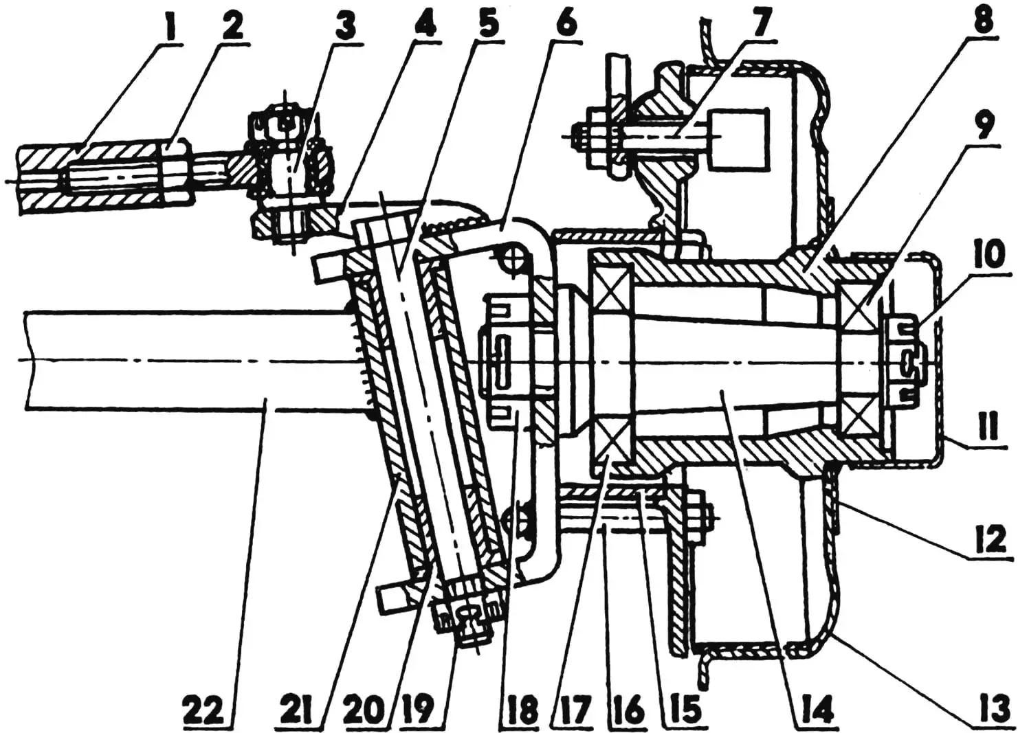
1 — steering rod (steel tube 22×3); 2 — lock nut M16; 3 — steering joint; 4 — steering arm (bicycle crank); 5 — kingpin (M16 bolt); 6 — bracket (leaf spring 60×9); 7 — brake mechanism (from SZD motorized wheelchair); 8 — hub; 9 — bearing 203; 10 — castle nut M16×1.5 with cotter pin; 11 — protective cap; 12 — overlay; 13 — brake drum (from SZD motorized wheelchair); 14 — axle (from automotive half-shaft); 15 — spacer ring; 16 — tie bolt; 17 — bearing 205; 18 — castle nut M20×1.5; 19 — castle nut M12; 20 — plain bearing (bronze, 2 pcs.); 21 — kingpin bushing (steel tube 26×3); 22 — front axle beam (cargo truck steering shaft)
A tubular transverse bracket is welded to the bandage tube in the middle of the beam. The lower end of the shock absorber rod is connected to it using a fork. The shock absorber cylinder is attached to an eye on the front crossbeam of the upper frame. The beam and crossbeam are connected to each other by two more springs. Round plates are inserted into the end turns of the springs for fastening, with which the lower ends of the springs are connected to the ends of the beam, and the upper ones to the crossbeam using stirrups.
The spindles (axles) of the front wheels are turned from an automotive half-shaft. The bearings in the hub are 205 and 203.
The steering knuckle brackets are made from a leaf spring with a cross-section of 60×9 mm. Steering arms made from bicycle cranks are welded to them. The axles are not welded to the brackets, but are screwed on with an M20×1.5 nut. The nut is cotter-pinned.
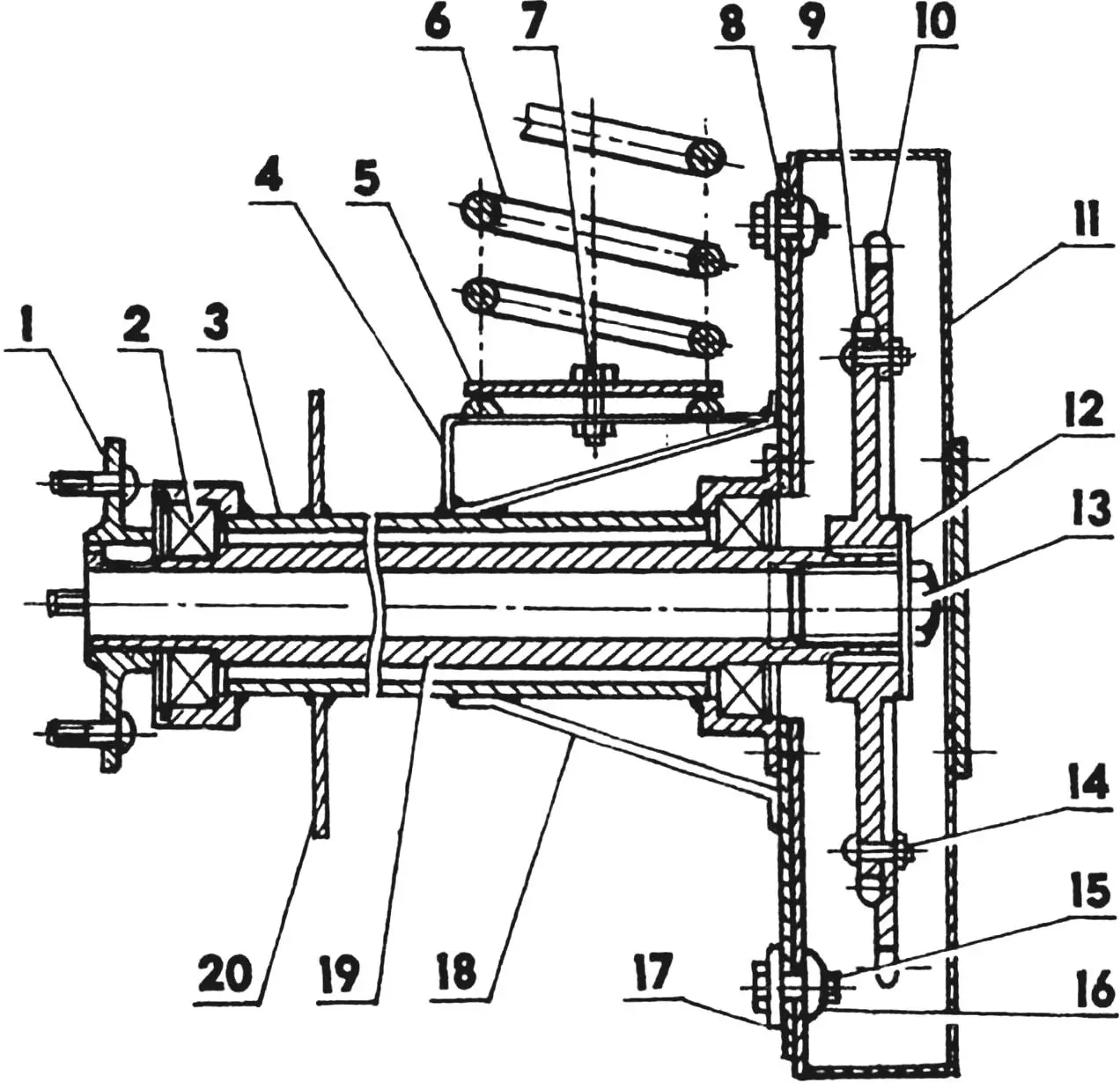
1 — wheel mounting flange (from “Electron” motor scooter);
2 — ball bearing 106 in housing (2 pcs.);
3 — half-axle housing (steel tube 48×3);
4 — spring mounting platform (steel St3, strip 30×2);
5 — spring mounting plate (steel St3, sheet s=10);
6 — spring 080 (steel 60G, rod Ø10, 9 turns);
7 — M10 bolt;
8 — pendulum arm flange (steel, sheet s=2);
9 — sprocket (z = 38, from “Tula” motor scooter);
10 — sprocket ring (z = 44, from “Voskhod” motorcycle);
11 — pendulum arm housing (steel, sheet s=1.5);
12 — washer;
13 — M20×1.5 bolt;
14 — M5 bolt;
15 — M10 screw (8 pcs.);
16 — bar-nut with two M10 holes (4 pcs.);
17 — plate-washer with two Ø10.2 holes;
18 — brace (steel, strip 30×2, 2 pcs.);
19 — shaft-half-axle (steel tube 33.5×4);
20 — support brake disc.
The rear suspensions of the motorized carts and the drives of the drive wheels differ significantly from each other. The first cart has a dependent suspension, an open chain drive, a single axle-shaft with both drive wheels without a differential. On the latter — a drive with an enclosed chain, two half-axles, but currently with one drive wheel. The suspension of each wheel is independent, made according to the pendulum arm principle. The arm-housings are suspended on a tubular axis, fixed in support-brackets made from automotive connecting rods. The transmission is located in the left housing: drive and driven sprockets and a drive chain with a pitch of 12.7 mm. The driven sprocket is combined: a 42-tooth sprocket ring from a “Voskhod” motorcycle is attached with M5 bolts to the hub of a 38-tooth sprocket (from a “Tula” motor scooter). If it’s necessary to use a smaller sprocket, the large ring can be removed, shortening the chain accordingly.
The rear wheel suspensions, as well as the front ones, of both motorized carts are spring-loaded. All springs are the same, 95 mm in diameter, wound from 10 mm rod (9 turns with a total height of about 300 mm) of spring alloy steel 60G. In the suspension with an open chain and sprocket, the springs are located on the inner side of the side members and rest on the rear end of the pendulum arm.
M. POYEZD
Recommend to read
 A PIECE OF IRON WILL BE SHARP
Qualitatively the condition blunt piece of iron of a plane is not easy even for an experienced wizard. Especially manually. As anyone tried, but to preserve the desired sharpening angle...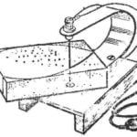 THERMOELASTIC FOAM
In our self-similar groups the foam — some of the most popular materials. One day we read in the "M-K" (No. 9, 1977) about the different ways of processing foam. We liked most of the...
