Fig. 2. Fee:
1, 10 — connecting wire, 2 — pins, 3 — jumpered, 4 — switch lever, 5, 6 — contact switch, 7 — button, 8 — base, 9 — bracket.
Fig. 3. Socket:
1 — connecting wire a 2 — tube Ø 10 mm, 3 — case.
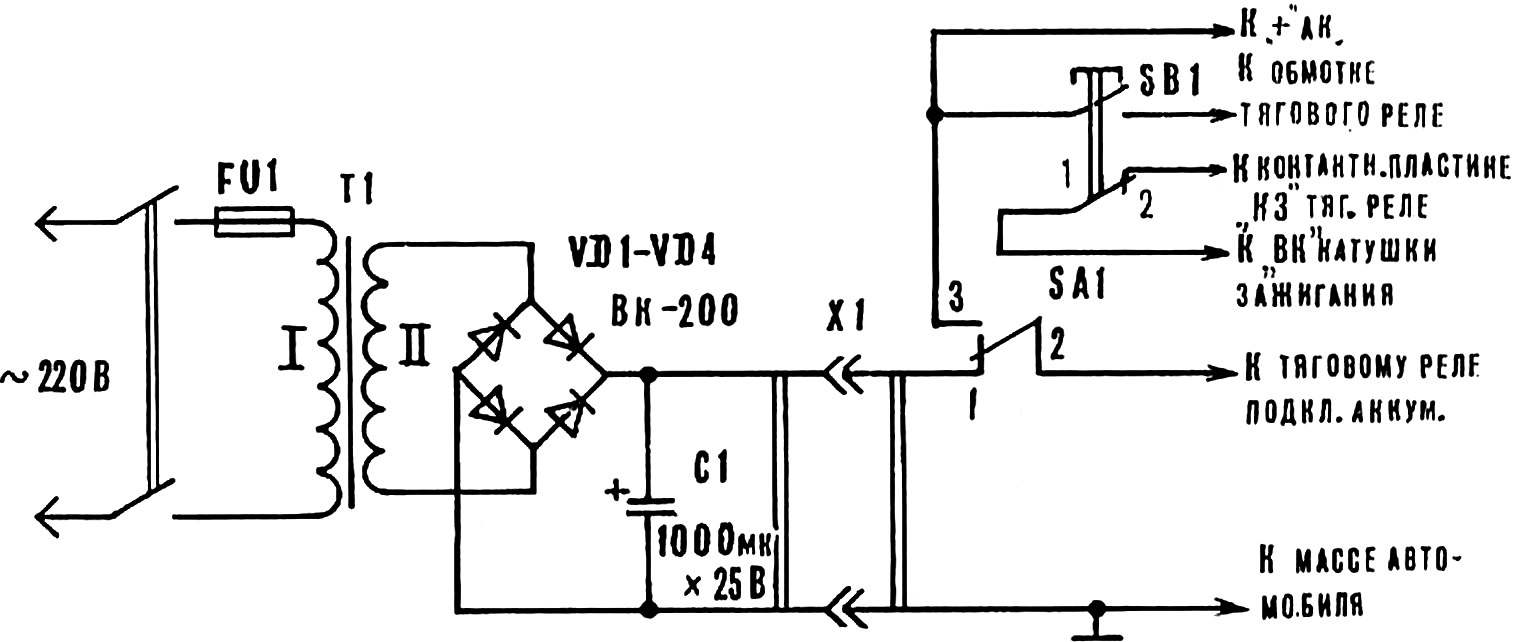
The device provides the cranking of the engine, and the engine is started with the ignition key or SB1 with the ignition on. Thus from the power source to receive energy from the vehicle battery.
The operation of the device consider the example of the car VAZ-2101. Connect the source to the onboard network via the connector X1 (Fig. 1). The switch SA1 is set to “network”, and the source connected to 220 V. the ignition Key translate in position “off”. By pressing the button SB1 carried out by the cranking of the engine. The power from the battery through the contacts of the SB1 is supplied to the traction relay. The power source through contacts 1-2 of switch SA1 is supplied to the traction relay and through the closed contacts of the traction relay to the coil side of the starter.
The engine is started with the ignition key as usual. Ignition start is performed also when the button SB1.
When using the device on the car “Moskvich-2140” and “Zaporozhets” enter into the work of the 1-2 contacts of the SB1 button, which prevents current flow from the source to the vehicle ignition system during operation of the traction relay. Wire connecting terminal plate “KZ” on the solenoid and clip the “VK” of the ignition coil must be disabled. The rest is as described above.
After the operation, the device is disconnected from the mains and from the car, and the switch SA1 is set to the “battery”.
As transformer T1 used converted autotransformer Latr-1M. The alteration consists in the following. Winding divided into two equal-number of turns of the part. Both halves are connected in parallel and donativum 45-50 turns of wire of Ø 1.5 mm. It will be a network winding. After the laying of the insulation layer wound winding of II, consisting of 15 turns of wire size 40-50 mm2 .
Diodes — VK-200 (or other designed for the rectified current of 200 A) are installed on the textolite plate without heatsink.
Connector X1 — homemade. The socket housing (Fig. 3) made of a PCB or other insulating material. In the housing is pressed on or glued sockets (copper tube Ø 10X1 mm), to which is soldered the connecting wires. The plug is mounted on the circuit Board (Fig. 2). Switch “battery network” is also homemade. The device is seen from the same figure.
The wires which carry power to the starter, should have a section 30-40 mm and may be shorter. The presence of the capacitor C1 is not required.
A. VOVK, S. sharivka, Kharkiv region.
Recommend to read HYDROFOIL This model was designed by students of Victor Pisarev, Alexei Knizhnikov and Nikita Novikov. They built it in the ship laboratory of the Moscow city Palace of pioneers. High speed of... RECUMBENT: LET’S HIT THE ROAD! In the late 70-ies in the press, especially in the journal "modelist-Konstruktor", wrote a lot about velomobiles. Was presented designs of various authors. Some argued that a new form of... 
 Every driver knows how it is sometimes difficult to start the engine of a car on a winter morning after long Parking. However, a relatively simple device powered from an AC mains voltage of 220 V will greatly facilitate this task. The device consists of two parts (Fig. 1), one AC power supply (voltage 12 to 14 V); the second part is mounted in the engine compartment of the vehicle. They are connected to each other using a special connector.