In my time, I had the opportunity to build and test many motorboats. The first to hit the water was the motorboat “Zvezdochka”, whose drawings were published in the October 1966 issue of the “Modelist-Konstruktor” magazine.
It is known that in rural areas, DIY enthusiasts are not spoiled by the wide range of construction materials available. What was needed to build “Zvezdochka” was not found for a long time. I had to make do with what was at hand at that moment, namely a steel sheet 1.8 mm thick. Naturally, the power set made of metal profiles and strips of various cross-sections, together with the zigged hull plating, gave the vessel a rather substantial mass.
The boat hull parts were welded using an electric arc from direct current using electrodes 4 mm in diameter, cleaned of coating. Welding intermittently was difficult for me at first, until I, as they say, got a feel for the metal and developed the skill. With this method, the weld looks like overlapping fish scales, and the weld structure appears somewhat porous.
When “Zvezdochka” was ready, I installed a “Vikhr” engine on it. However, trial operation revealed a number of boat shortcomings: poor longitudinal stability, water splashing over the transom when the engine suddenly stopped, and so on.
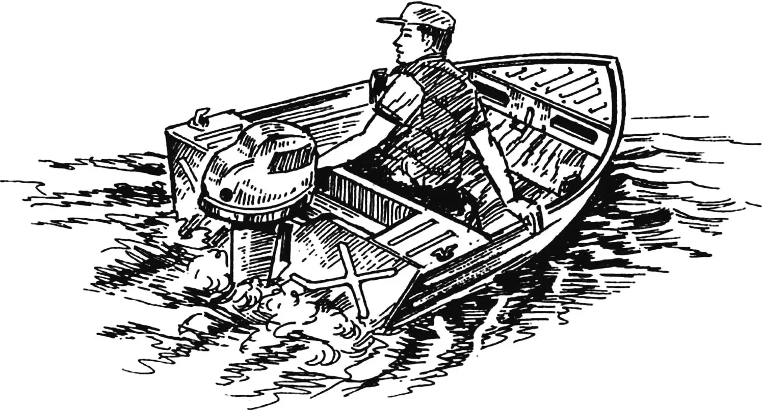
I had to modernize the boat. Several times, in fact. It acquired side buoys, an engine well, and much more. In a word, the “Zvezdochka” project motorboat became a kind of laboratory for me, where various technical solutions were tested. Over time, with the accumulation of experience in identifying and eliminating shortcomings, the “Mirage” motorboat appeared.
Why was it given such a name? The fact is that under certain lighting conditions on the river, especially in hot weather, the boat hull painted in light paint visually merges with the water surface at some distance from the observer, becoming somewhat ghostly. So to speak, STEALTH technology in action.
Why was “Mirage” chosen as the subject for publication?
Let me immediately clarify that I do not in any way claim exclusivity for this design. I simply wanted to show what can be done with modest material and technical capabilities of a DIY enthusiast, guided by the wise saying “patience and hard work will overcome everything.”
“Mirage” was chosen because, in my opinion, it has the simplest form and manufacturing technology compared to other options. As for the simplicity of the boat’s lines, it is largely predetermined not so much by the hull design as by the choice of materials. Steel, to put it mildly, is far from the best material for building a motorboat. Steel has high specific weight, poor corrosion resistance, especially in water, and many other disadvantages. However, steel is easy to work with and, most valuable, welds well with a conventional electric arc.
What exactly is “Mirage”?
This is a small-sized, fully welded boat with partially load-bearing hull plating, equipped with a “Vikhr” outboard motor rated at 20 hp (14.7 kW). Its maximum speed with one person on board is 48 km/h.
During water trips, three people can comfortably fit in the fairly spacious cockpit of the motorboat; for amateur fishing, two. “Mirage” was created precisely for these purposes. It does not have signal/distinctive lights or remote engine control. Due to the low deadrise of the bottom and other design features of the boat, its operation is not permitted when wave height exceeds 30 cm.
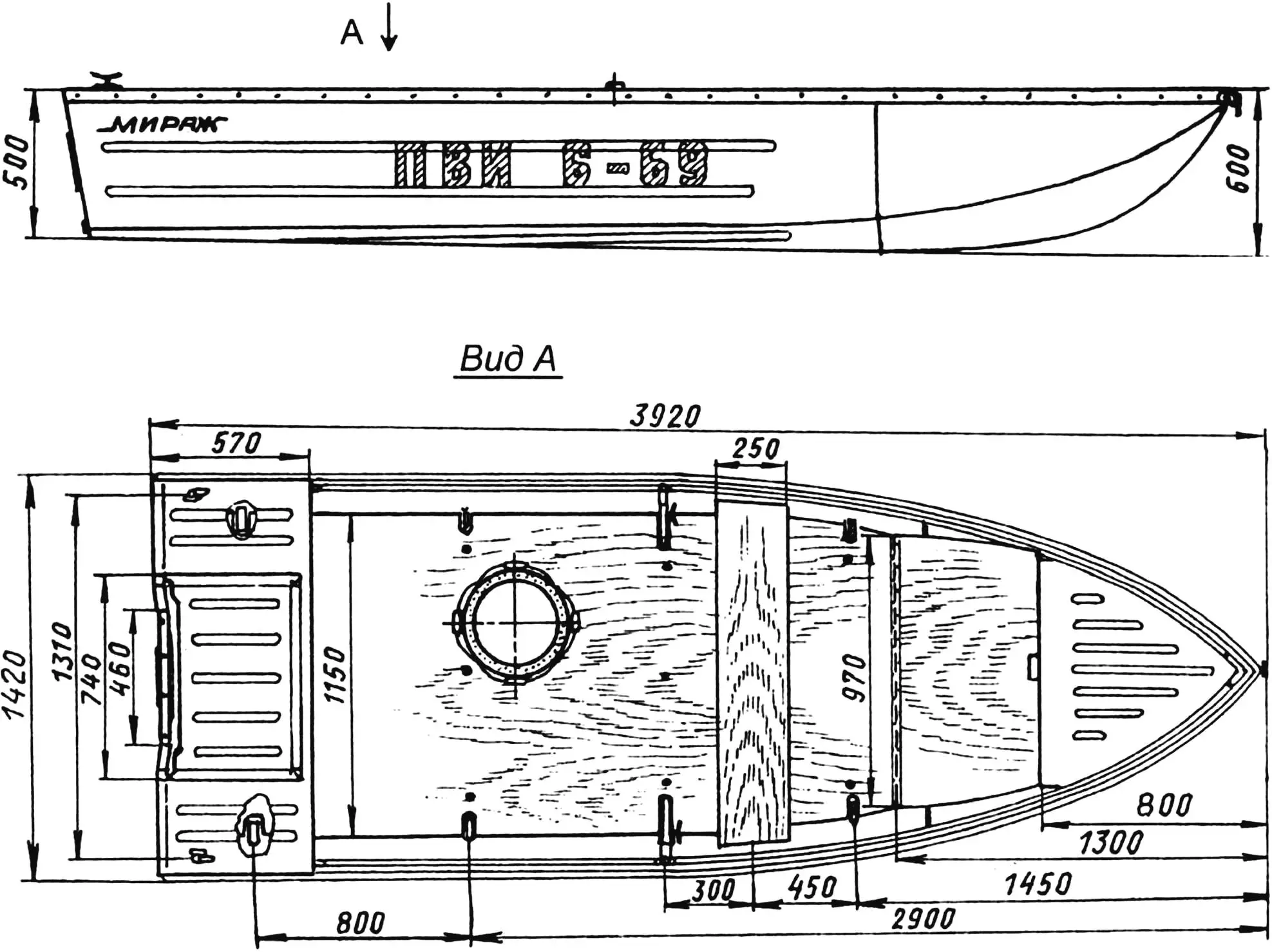
The forepeak of the hull has a fairly spacious storage compartment that is loaded through hatches cut in the forward bulkhead. (It should be noted that this bulkhead is not vertical but inclined toward the stern by 2°.)
50 mm below the edges (coamings) of the hatches in the forepeak, a forward flotation block made of PS-1 grade foam is rigidly secured. The block was smoothed with a hot iron before installation, which made its surfaces smooth and strong. Since the hatches do not have covers, items loaded into the storage compartment are prevented from falling out during rough seas and shaking by those same 50 mm high coamings.
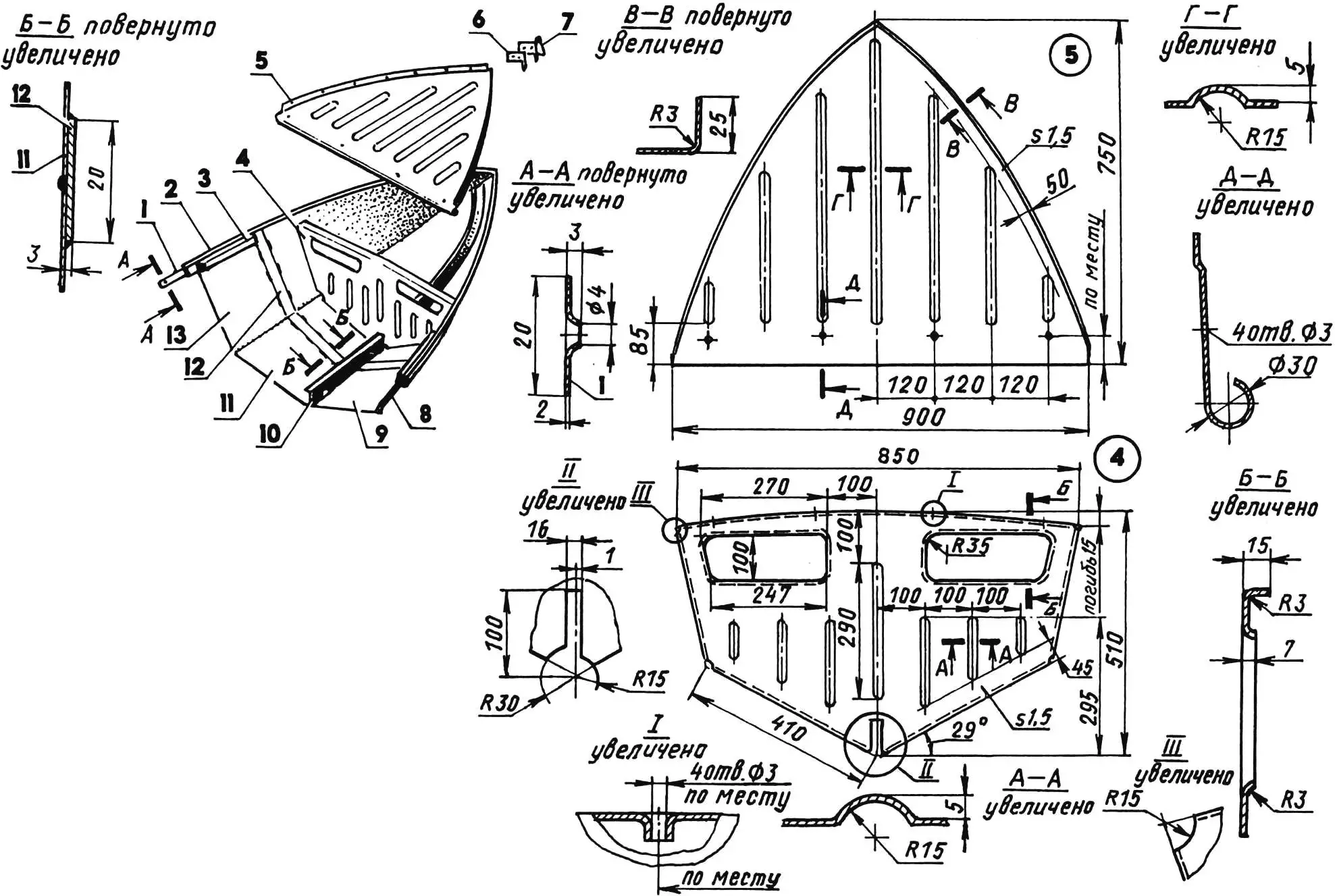
1 — strake; 2 — coaming; 3 — gunwale; 4 — forward bulkhead; 5 — forward deck (steel, sheet s1.5); 6 — inner plate (steel, sheet s2); 7 — outer plate with ring and towing eye (steel, sheet s2; rod Ø8); 8,13 — side panels; 9,11 — bottom panels; 10 — keel; 12 — butt strap (steel, strip 20×1.5)
In the cockpit, a floorboard made of bakelized plywood 7 mm thick is secured to the floor timbers with twelve M6 screws with round heads and slots for a flat screwdriver. The floorboard almost completely covers the bottom and has minimal gaps with the sides; at the locations where the chine knees exit, corresponding cutouts are made in it.
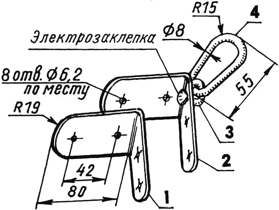
1 — inner plate (steel, sheet s2); 2 — outer plate (steel, sheet s2); 3 — ring (steel, rod Ø8); 4 — eye (steel, rod Ø8)
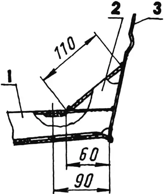
Forward, at a distance of 1300 mm from the bow, the floorboard ends. There, a sheet of bakelized plywood—the bottom storage compartment lid—is attached to it with a piano hinge. With its free forward edge, in the center of which a hand grip is cut, the lid rests on the forward bulkhead at an angle of 25° to the horizontal and forms another volume for cargo underneath. Thus, the forward storage compartment is used for light and water-sensitive items, while the bottom one is for rougher items: ropes, boots, anchors, and so on. And one more thing. Even with our sparse summer sun and rare calm weather, one can relax and sunbathe perfectly on the floorboard: the bottom storage compartment lid serves as a convenient headrest, and the fairly high boat sides protect the sunbather from the wind.
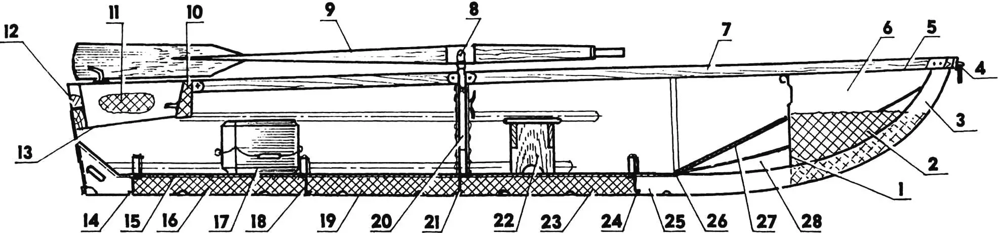
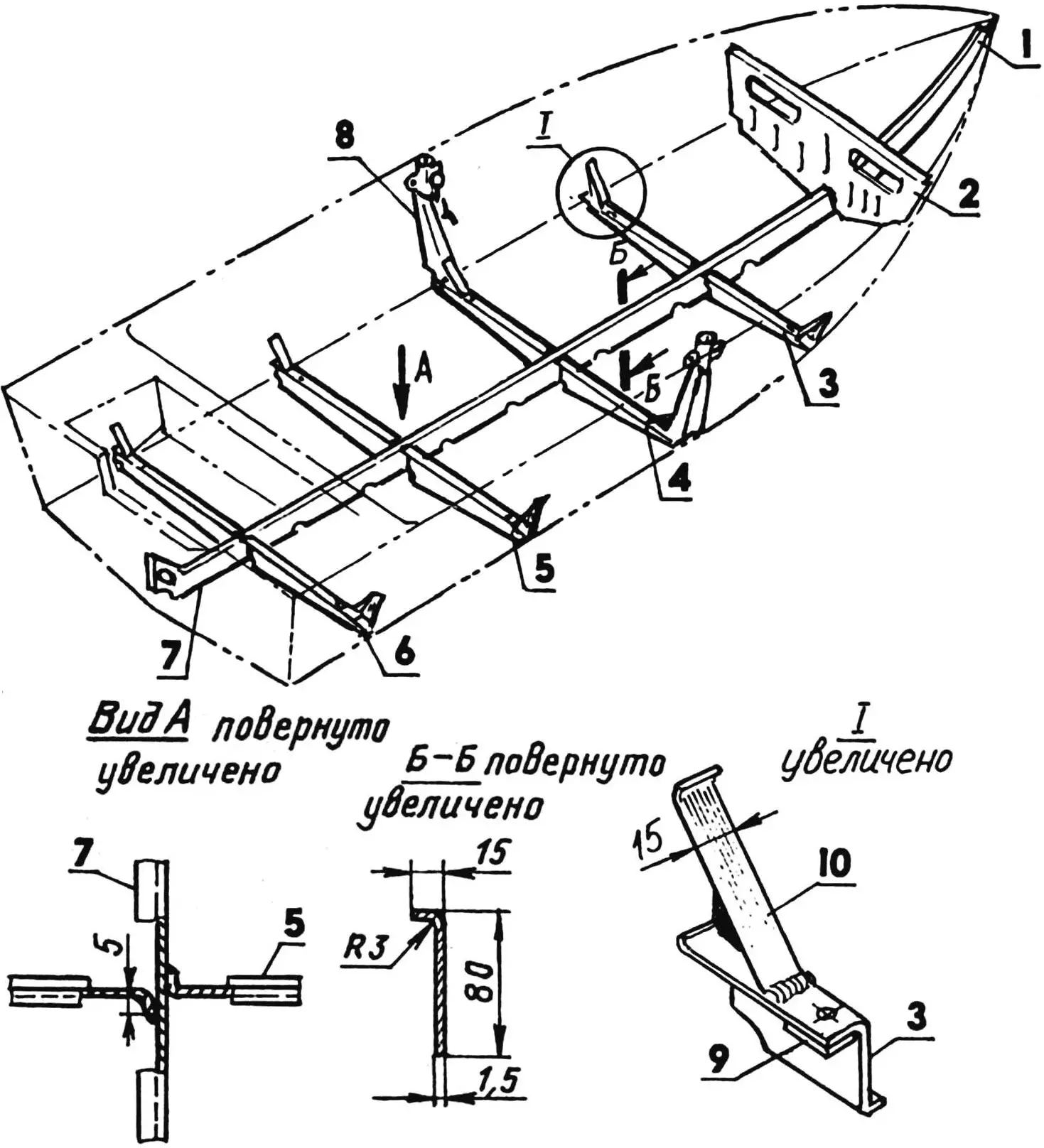
1 — forward bulkhead; 2 — forward flotation block; 3 — stem; 4 — towing device; 5 — forward deck; 6 — forward storage compartment; 7 — gunwale; 8 — oarlock; 9 — oar; 10 — midship flotation block; 11 — aft flotation block; 12 — transom flotation block; 13 — engine well bottom of the stern; 14,18,21,24 — floor timbers; 15 — floorboard; 16,19,23 — bottom flotation blocks; 17 — adjustable seat; 20 — top timber with oarlock socket and anchor/mooring cleat; 22 — removable seat; 25 — keel; 26 — hinge (piano hinge); 27 — bottom storage compartment lid; 28 — bottom storage compartment
Under the floorboard are flotation blocks made of PVC-1 grade foam, profiled to the bottom. Clamped between the floorboard and bottom, these blocks, together with the power set, absorb impact loads that occur when the hull meets waves.
The forward deck is made of sheet steel 1.5 mm thick. The deck edge facing the cockpit is given a rounded shape so that when pulling the motorboat ashore, this rounded edge can be used as handles. On the other edges of the deck, flanges are made, and on the surface, along the centerline—stiffening elements in the form of embossings—ZIGS.
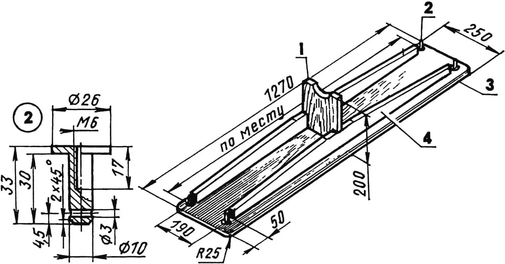
1 — stop (pine, board 190×20); 2 — mounting pin (4 pcs.); 3 — seat (pine, board 250×18); 4 — stiffening rib (pine, strip 100×10, 2 pcs.)
Incidentally, the forward deck was installed last—along with the coamings and gunwales. To be more specific, I first painted the inner surfaces of the forepeak, placed a flotation block in it that was pre-fitted to shape and treated with a hot iron, and only then installed the deck painted on the bottom in place, lightly tacking it with electric welding to the sides at four points. After that, alternating in a checkerboard pattern, I secured the coamings and gunwales with 4×40 mm screws. Under the screw heads along both coamings along the entire length of the hull, I placed a strake—a steel strip with a cross-section of 20×2 mm. In addition, the coamings and gunwales were additionally tightened in places around the perimeter with ten M6 bolts.
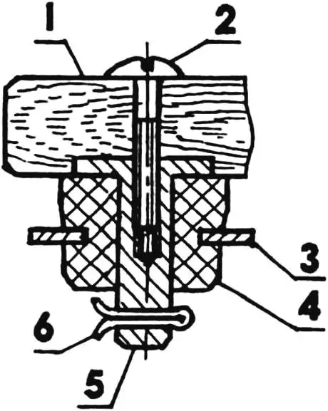
1 — seat; 2 — M6 screw; 3 — stop bracket; 4 — stop damping bushing; 5 — mounting pin; 6 — cotter pin
In the bow of the boat, I installed a towing device consisting of two angle plates made of sheet steel 2 mm thick, to one of which (outer) a ring with a towing eye made of 8 mm diameter steel rod is welded. The plates, together with the coamings, gunwales, and forward deck flanges clamped between them, are secured to the sides in place with four M6 bolts with round heads.
1 — damping bushings (rubber, L20); 2 — bracket (steel, sheet s2)
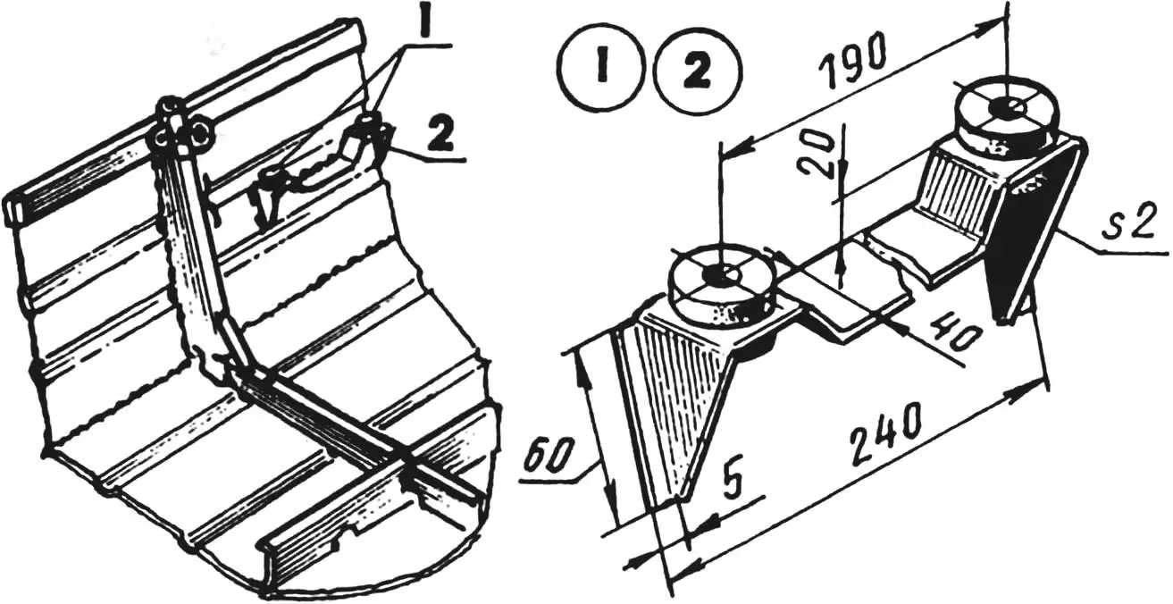
Before the top timbers, I welded brackets to the sides for mounting the removable seat. The brackets, bent from sheet steel, have rubber bushings for metal pins screwed into the corners of the seat. Thus, at the shore in nature, the seat can easily be removed from the boat and placed on the shore. And when using the motorboat by one person, the removable seat can be left behind entirely, and an adjustable seat can be taken instead, made of PVC-1 grade foam and covered with “bolon’ya” fabric. Around its circumference, it has loops made of 5 mm diameter nylon cord with handles and, if necessary, can serve as a rescue float.
1 — M8 bolt; 2 — bracket flange (steel, sheet s5); 3 — bracket (steel, rod Ø8); 4 — locking handle with M8 nut; 5 — pin flange (steel, sheet s5); 6 — washer (hard rubber s5); 7 — pin (steel, rod Ø12)
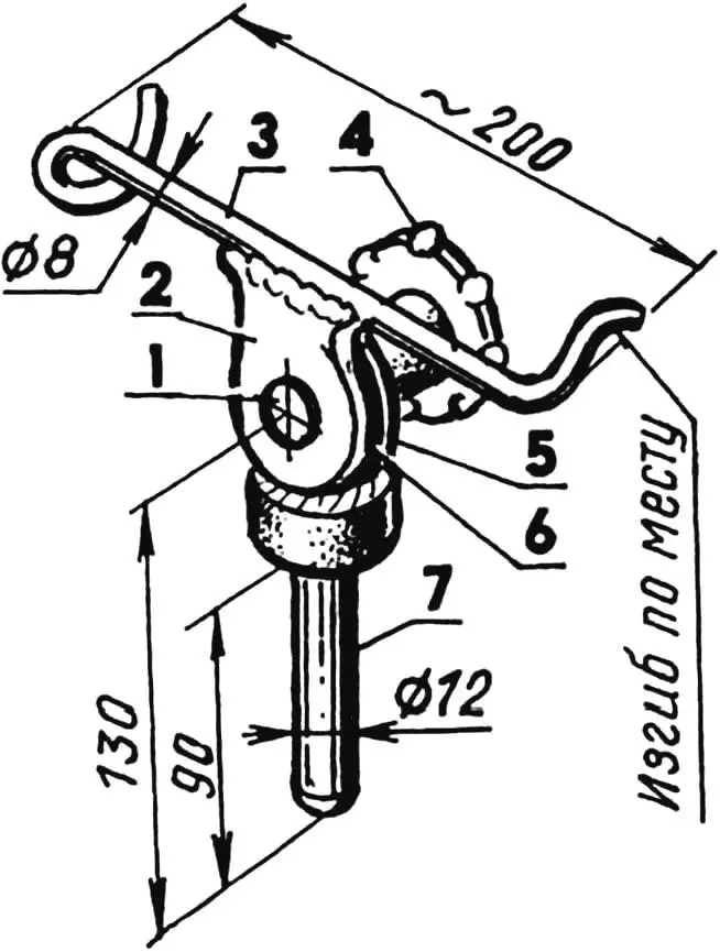
For convenience when fishing with a rod, a special device is provided—a rod holder with the ability to adjust the rod position both vertically and horizontally. The device is inserted into any of the oarlock sockets and secured with a screw.
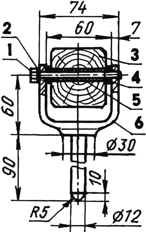
1 — M8 bolt; 2 — spring washer; 3 — oar; 4 — washer (Teflon, tube 16×4, 2 pcs.); 5 — bushing (Teflon, tube 12×2); 6 — oarlock
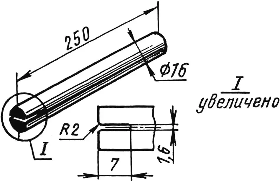
The “Mirage” motorboat is equipped with two oars made of dry spruce. After complete carpentry processing, the oars were coated with two layers of hot linseed oil with mandatory drying between layers and painted with waterproof paint.
The oarlocks are made of steel forgings with subsequent machining and bluing. Teflon bushings of appropriate sizes are pressed into the oar holes and oarlock sockets.
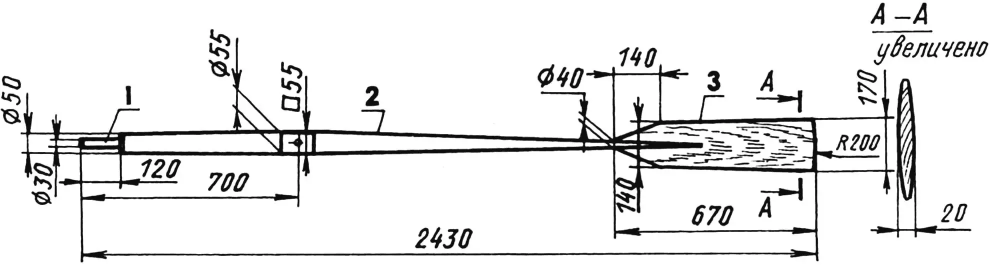
1 — handle; 2 — shaft; 3 — blade
For mooring and anchor stations, four cleats are provided on the boat hull: two on the top timbers, under the oarlocks, and two on the stern, which also serve as sockets for oar blades in the non-working position.
1 — floor timber; 2 — chine knee (steel, sheet s1.5); 3 — side panel
The rigidity of the entire motorboat structure is ensured collectively by its power set (keel with stem, top timbers, floor timbers, and chine knees), forward and aft decks, engine well, coamings and gunwales, as well as technological elements—zigs on flat surfaces, keel, chine, and transom flanges for welded seams.
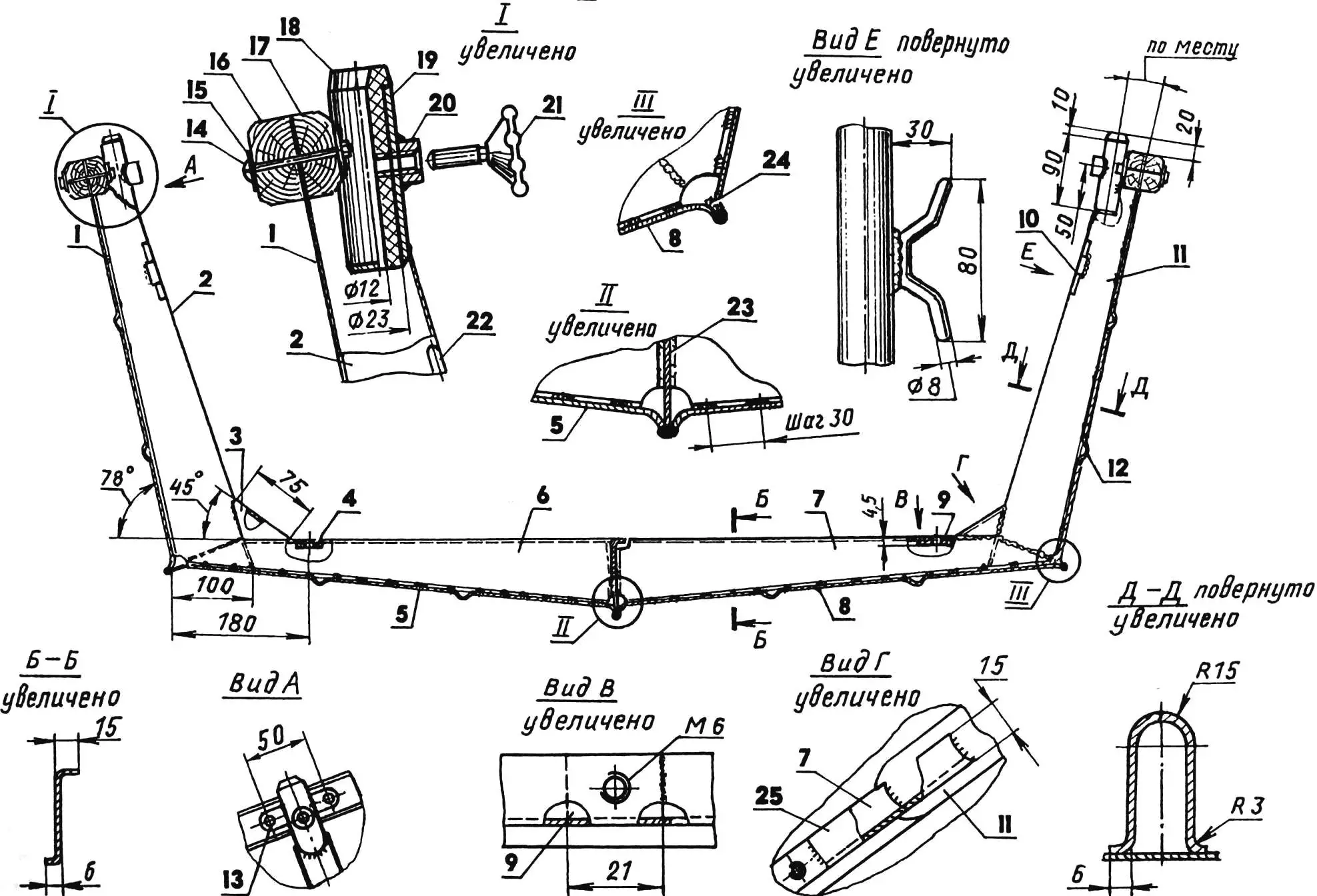
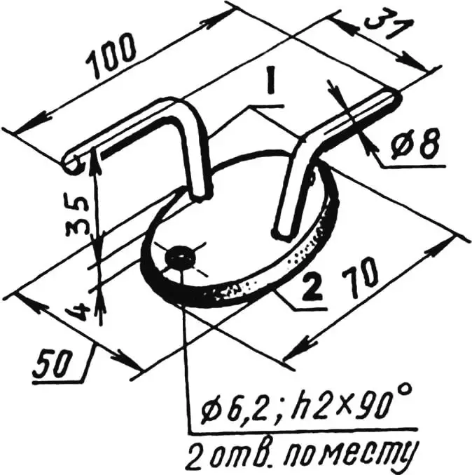
1,12 — side panels (steel, sheet s1.5); 2,11 — top timbers (steel, sheet s1.5); 3,25 — chine knees (steel, sheet s1.5); 4,9 — welded M6 nuts (steel, sheet s3); 5,8 — bottom panels (steel, sheet s1.5); 6,7 — floor timbers (steel, sheet s1.5); 10,22 — anchor/mooring cleats (steel, rod Ø8); 13 — welded eye (steel, sheet s2, 4 pcs); 14 — M6x50 bolt; 15 — strake (steel, strip 20×2); 16 — coaming (pine, block 40×20); 17 — gunwale (pine, block 40×20); 18 — oarlock bearing (Teflon); 19 — oarlock bearing socket (steel, tube 27×2); 20 — welded M8 nut; 21 — M8 locking screw; 23 — keel (steel, sheet s1.5); 24 — gasket (steel, sheet s1.5)
The engine well of the stern is welded from separate panels. In the forward corners of the well, brackets are built in for a carabiner rope that secures the outboard boat motor against accidental loss.
In the front, a rubber-fabric insert is flush-mounted in the engine transom board for the motor mounting clamp plates, and in the back, a plate made of bakelized plywood 7 mm thick is made. The entire package—insert, transom board, and plate—are connected together with screws and through M6 bolts.
1 — legs (steel, rod Ø8); 2 — base (steel, sheet s4)
For draining water from the hull, a hole with a threaded duralumin plug and a rubber sealing ring is provided in the transom.
In addition, the stern, as the most loaded part of the boat hull, is equipped with many flotation blocks. Specifically, one midship block (made of PS-1 grade foam)—between the aft deck backrest and the forward part of the engine well; two voluminous aft blocks (made of PVC-1 grade foam)—between the sides and the engine well sidewalls; finally, two small transom blocks (made of PS-1 foam)—between the block covers and the transom.
Now I would like to dwell in more detail on the technological features of assembling the motorboat hull.
1 — stem; 2 — forward bulkhead; 3,4,5,6 — floor timbers No. 1—4; 7 — keel; 8 — top timber; 9 — welded M6 nut (steel, sheet s3, 8 pcs); 10 — chine knee (8 pcs)
The main feature is that first, on the building berth, the hull was assembled from bottom and side panels and the longitudinal power set (keel with stem) using electric welding, and only then was the transverse power set installed in it. All parts of this set (floor timbers, top timbers, and chine knees) were manufactured to dimensions taken from the boat hull in place, so their exact dimensions are not given in the drawings.
The second technological feature was that the steel sheets I had did not allow cutting the bottom and side panels in one piece. I had to extend them butt-welded, using backing strips (steel strips with a cross-section of 20×1.5 mm) under the welded seams. Welding with a 1 mm gap between sheets was done on a flat copper backing, which eliminated the possibility of burn-through.
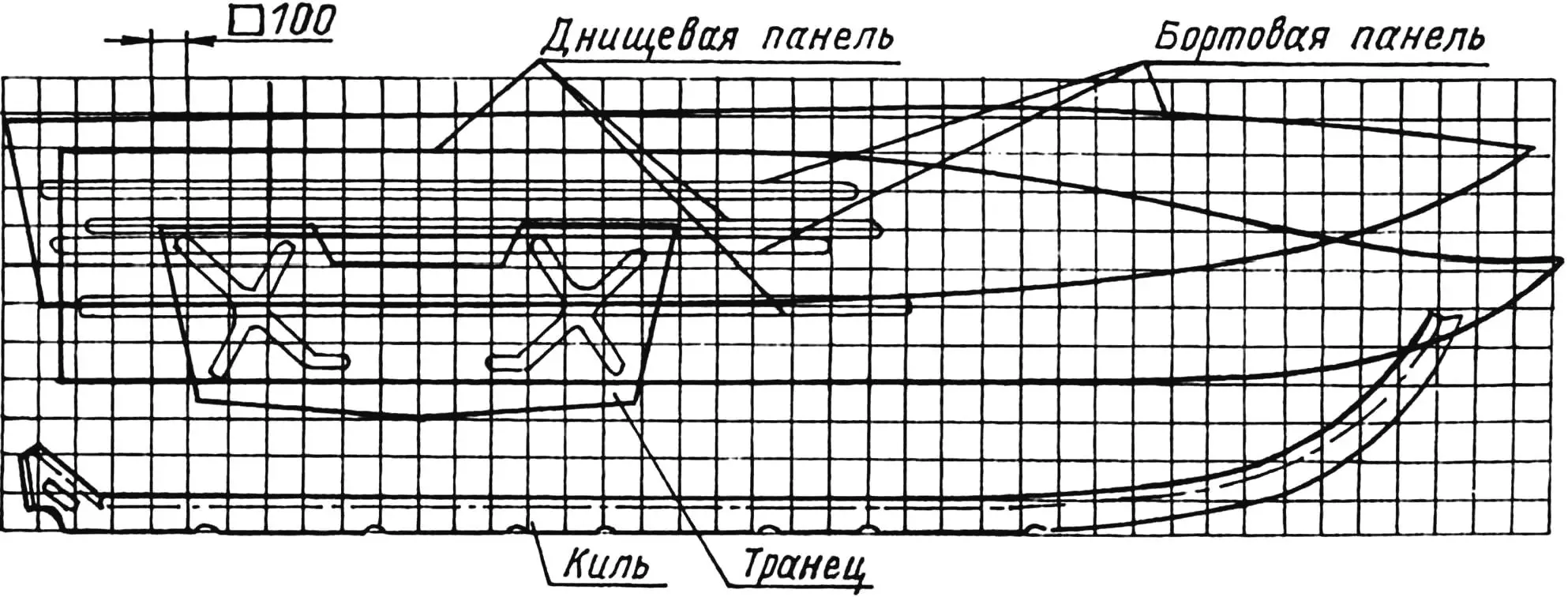
The contours of the bottom and side panels and the keel with stem were transferred to the steel sheets using special templates. The latter were cut according to a coordinate grid full-size from thin fiberboard.
I will show the further sequence of manufacturing these parts using the example of one side panel.
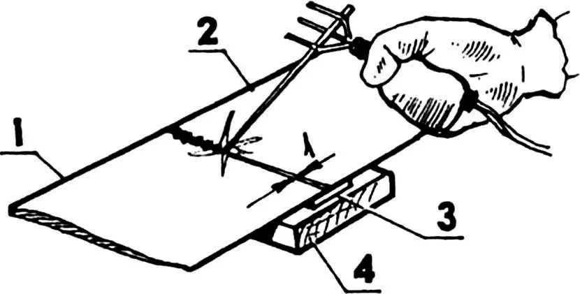
With a sharp scriber, I transferred the panel contour from the template to the steel sheet (it includes the future flange for the welded seam at the bottom). Relative to the chine line, I marked the locations of the zigs. (To form these stiffening elements, I previously made a special device and a forming hammer.) I formed the zigs as carefully as possible, with a slight stretch of the metal in one pass along the entire length of the zig. This seemingly simple work required patience and skill.
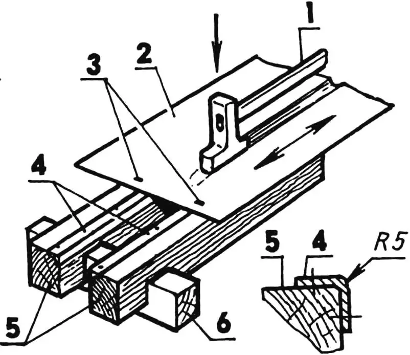
1 — forming hammer; 2 — steel sheet being processed; 3 — fixators (nails); 4 — supports (steel, angle 50x50x5); 5 — longitudinal logs (pine, beam 180×180); 6 — transverse log (pine, 180×180, 2 pcs.)
After forming both zigs, I turned the sheet over and straightened it on a flat surface with blows from a wooden mallet. Then I cut the side panel as accurately as possible along the marking with electric shears. It should be noted that side panels (as well as bottom panels) folded together in pairs should match exactly in contour. I corrected obvious mismatches. Otherwise, the hull symmetry would be disrupted and assembly would be complicated.
With a specially made tool, I made flanges along the chine line at an angle of approximately 45° toward the zig hump on all bottom and side panels.
Next, I assembled the stern, welding all transom parts and the engine well into one piece. Then I welded the keel with its knee flange to the stern.
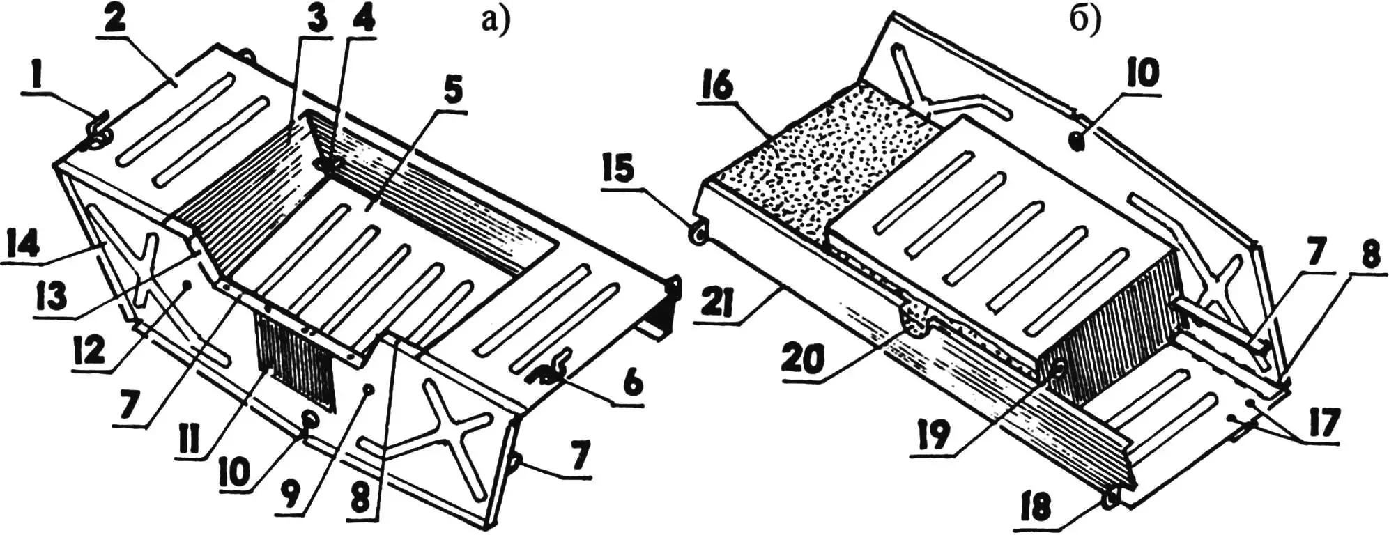
1,6 — anchor/mooring cleats; 2 — aft deck; 3 — port engine well sidewall; 4 — port safety bracket; 5 — engine well bottom; 7 — through transom stringer: 8,13 — starboard and port transom stringers; 9,12 — holes for draining water from the engine well; 10 — threaded plug for draining water from the hull; 11 — plate for outboard motor clamp stops; 14 — transom; 15,18 — mounting lugs to sides; 16 — port aft flotation block (starboard conventionally not shown); 17 — M6 nuts for starboard cleat mounting; 19 — backing washer for starboard safety bracket; 20 — midship flotation block; 21 — aft deck backrest
Final hull assembly was carried out on a building berth—a flat plank decking with trestles. The decking boards were whitewashed with lime for fire safety, and then the necessary markings were applied in the form of the hull centerline and side contours.
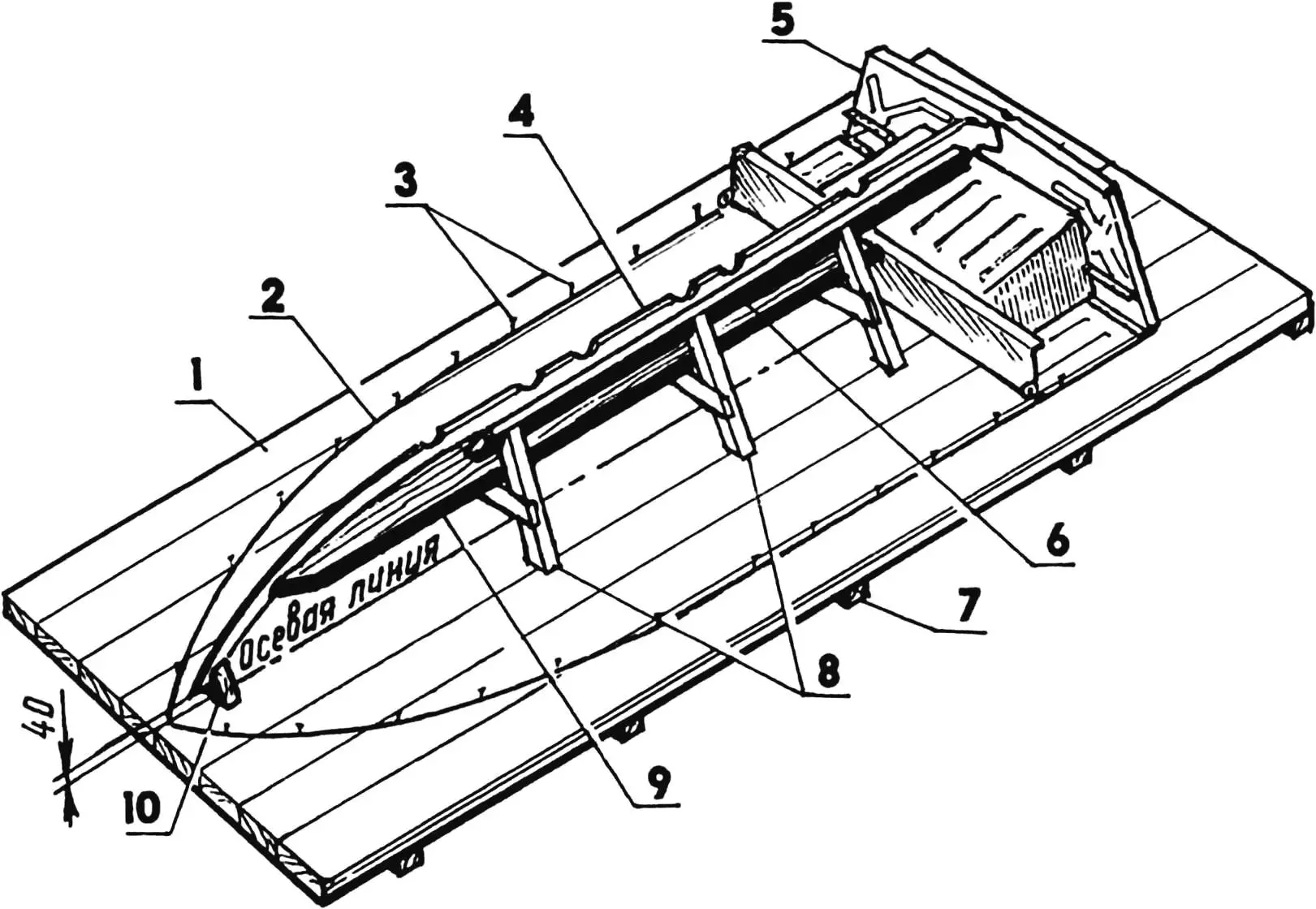
1 — berth decking (pine, board s40); 2 — motorboat side contour; 3 — stop limiters (nails); 4 — keel; 5 — stern; 6 — wedge (pine, beam 50×50, 2 pcs.); 7 — log (pine, beam 180×100,5 pcs.); 8 — trestles (3 pcs.); 9 — support (pine, board s40); 10 — stem fixator (pine, beam 180х100)
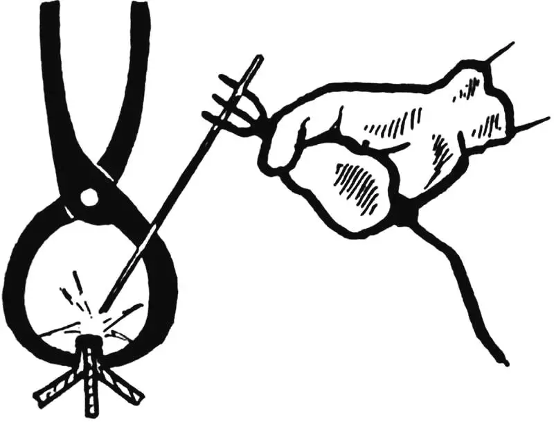
On the berth, I installed the inverted stern with the keel welded to it, oriented along the centerline, and secured it. Giving the bottom and side panels the necessary curvature by hand on a flat log, I tacked them one by one with electric welding. In doing so, I used steel strips with a cross-section of 10×1.5 mm, inserting them between the flanges of the bottom, side panels, and transom (to increase the thickness and strength of the welded seams), as well as carpenter’s pliers, compressing the areas to be welded with them.
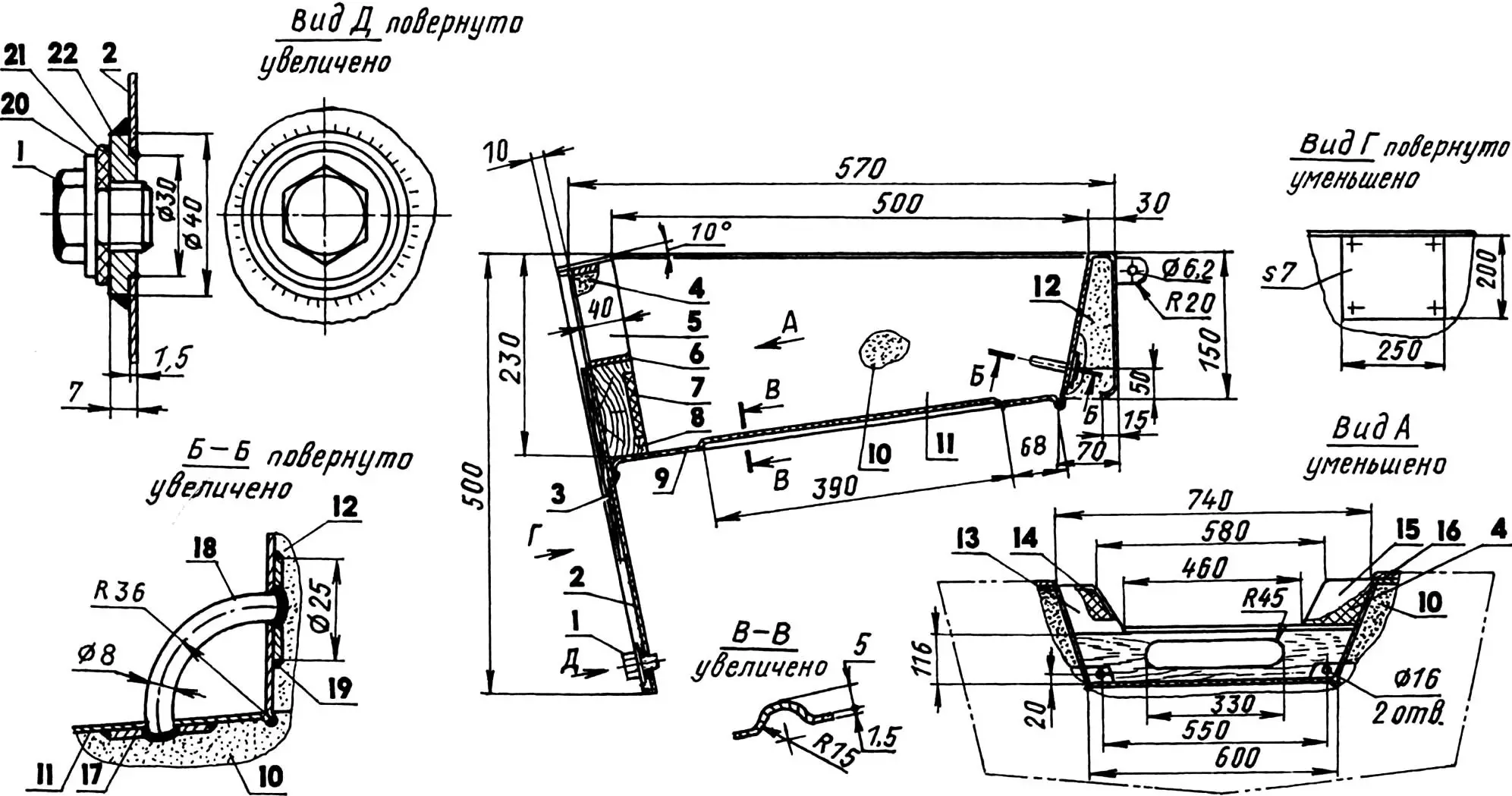
1 — threaded plug M16x1.5 (D16T); 2 — transom; 3 — plate (bakelized plywood s7); 4,14 — transom flotation blocks (PS-1 foam); 5 — port transom stringer (steel, strip 40×4); 6 — through transom stringer (steel, strip 40×4); 7 — insert (rubber-fabric mat s8); 8 — transom board (pine, board s40); 9 — engine well bottom (steel, sheet s1.5); 10 — port aft flotation block (PVC-1 foam); 11 — port engine well sidewall (steel, sheet s1.5); 12 — midship flotation block (PS-1 foam); 13,15 — transom flotation block covers (steel, sheet s1.5); 16 — aft deck (steel, sheet s1.5); 17,19 — backing washers (steel, sheet s2); 18 — port safety bracket (steel, rod Ø8); 20 — washer; 21 — sealing ring (rubber); 22 — welded M16x1.5 nut (steel, sheet s7)
Then I finally welded the hull, using direct current reverse polarity welding current, selected experimentally in the range of 25—90 A, and electrodes with diameters from 2 to 4 mm.
1,2 — sheets to be welded; 3 — butt strap (steel, strip 20х1.5); 4 — backing (copper, strip 60×10)
I draw attention to the fact that all the longest welded seams are located on the outside of the hull. External seams are much more convenient to weld, and their quality turns out to be quite high.
When the seams had cooled, I turned the boat over, marked the locations of the power set elements, and installed these elements, tacking them with electric welding points. At the same time, I did not forget to control the hull geometry relative to the horizontal top of the transom with a wooden block placed across the sides. After all, even with the most accurate execution of assembly operations, errors are possible—small distortions and thermal warping.
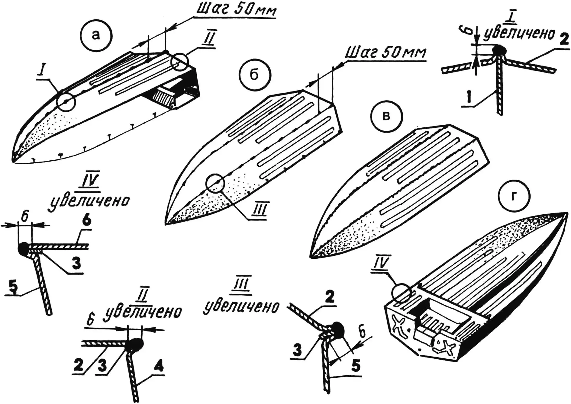
a — spot tacking of bottom panels to keel and stern; b — spot tacking of side panels; c — full welding of bottom and side panels with continuous seams; d — full welding of side panels and aft deck;
1 — keel; 2 — bottom panel; 3 — gaskets (steel, sheet s1.5); 4 — transom; 5 — side panel; 6 — aft deck
After welding work, I thoroughly cleaned all seams with a metal brush, degreased with gasoline, primed, and painted all surfaces. And after final assembly, installing the flotation blocks, coamings, and gunwales, I finally painted the motorboat hull with waterproof enamel paint.
V. PETROV
Recommend to read
 “SWAN LAKE”
While on vacation in Anapa with a group of tourists during a short-term bus stop near one of the nearby houses saw in the front garden and managed to photograph is my favourite, "a lake... SCREWDRIVER-HERO
It is not easy to Unscrew a tight screw, rusted bolt, firmly seated the screw, if the screwdriver is narrow and uncomfortable handle. However, to improve it and make the screwdriver a...
