 On our market there are now a lot of imported bikes with a large (over a dozen) number of speeds. But fascinating these machines are, perhaps, only youths. Experts understand that to take full speed full still impossible: difficult even to choose the correct gear and often switch them on the go is not only tiring but also unsafe. Because switching is required usually in difficult driving conditions or cornering, when the hands should firmly hold the steering wheel, and one of them is necessary to manipulate the lever. As you know, the cars are only 4 — 5 speeds, and the drivers prefer to upgrade to automation.
Abroad release sleeve multi-speed rear drive wheel (for example, planetary gear or hydromechanical), which provides automatic and continuous change of the gear ratio. But their efficiency is much lower than that of a conventional chain transmission. Of course, riding and Cycling with this sleeve is light-hearted and pleasant, but pleasure or sports significant muscle loss of energy is undesirable, that is, the bushing with such automation is unacceptable.
I designed multi-speed bushing rear wheel with automatic switching of gears, almost with the same efficiency as the standard bushings tourism and sport bike with a manual shift.
Overall and mounting dimensions of the designed sleeve is approximately the same as sleeve road bike with the foot brake, so it is no problem to insert into a standard wheel. But drive manual gearboxes (long cables, levers and shifters) can be discarded as unnecessary. The bike is not only a little better, but also become a bike-a machine without excessive loss of energy. Switching speeds are though automatically, but classically—swapping chain from sprocket to sprocket. Manages the same transfer itself bushing. The task of the cyclist in this case—only to pedal with affordable and comfortable frequency.
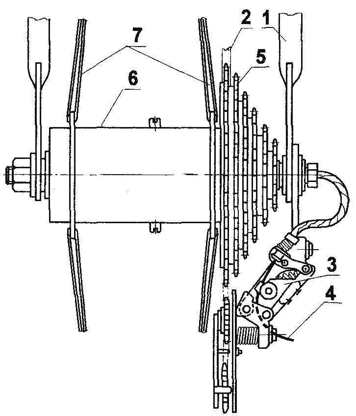
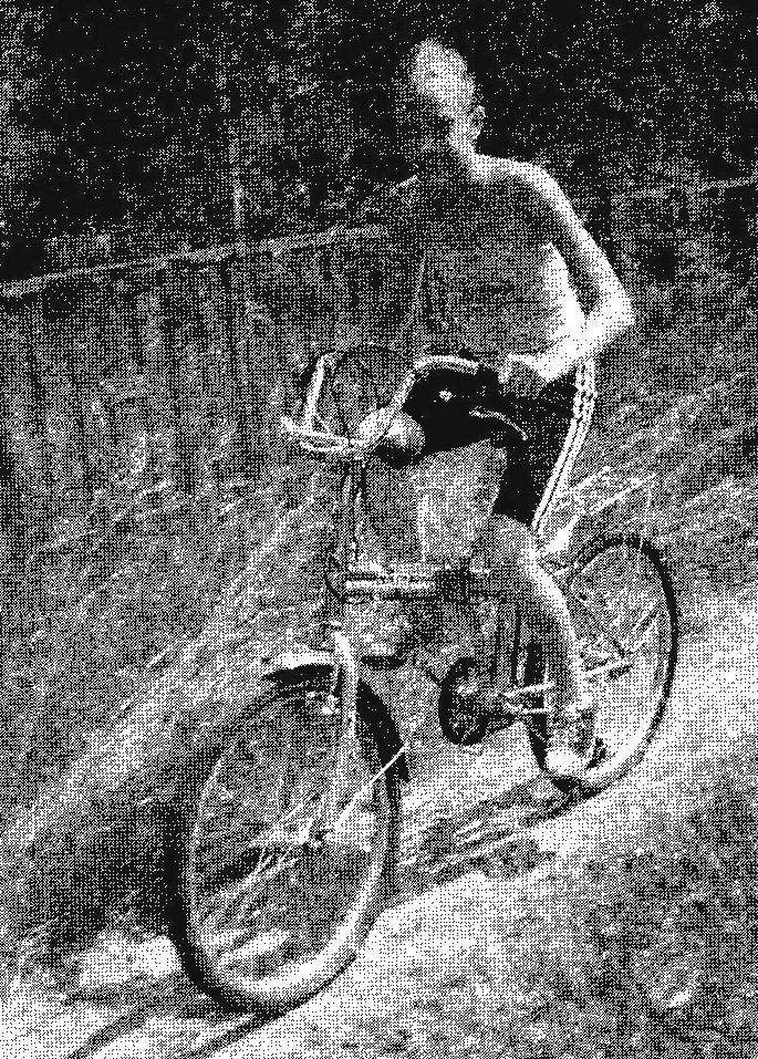
Fig. 1. Sleeve multi-speed automatic shifter:
1 —rear fork of the Bicycle; 2—chain drive (chain t = 12,7); 3—carriage speed switch (standard); 4—rope; 5—block sprocket; 6 — bushing automatic shifter; 7—spoke wheels rear drive wheel
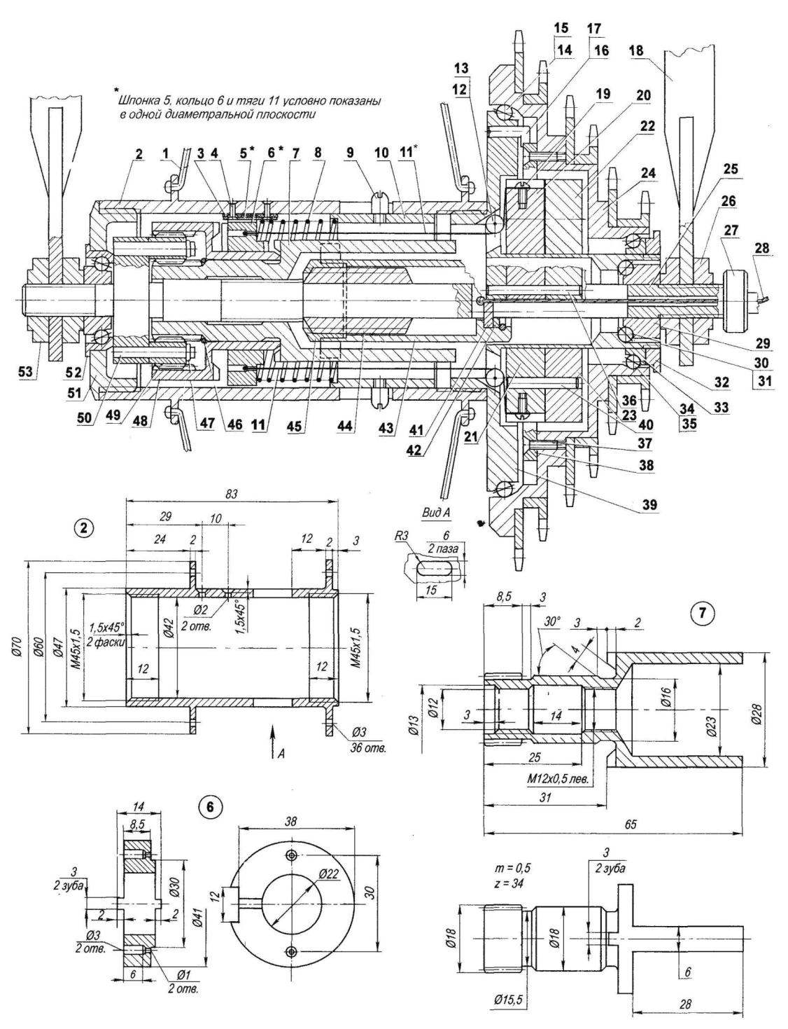
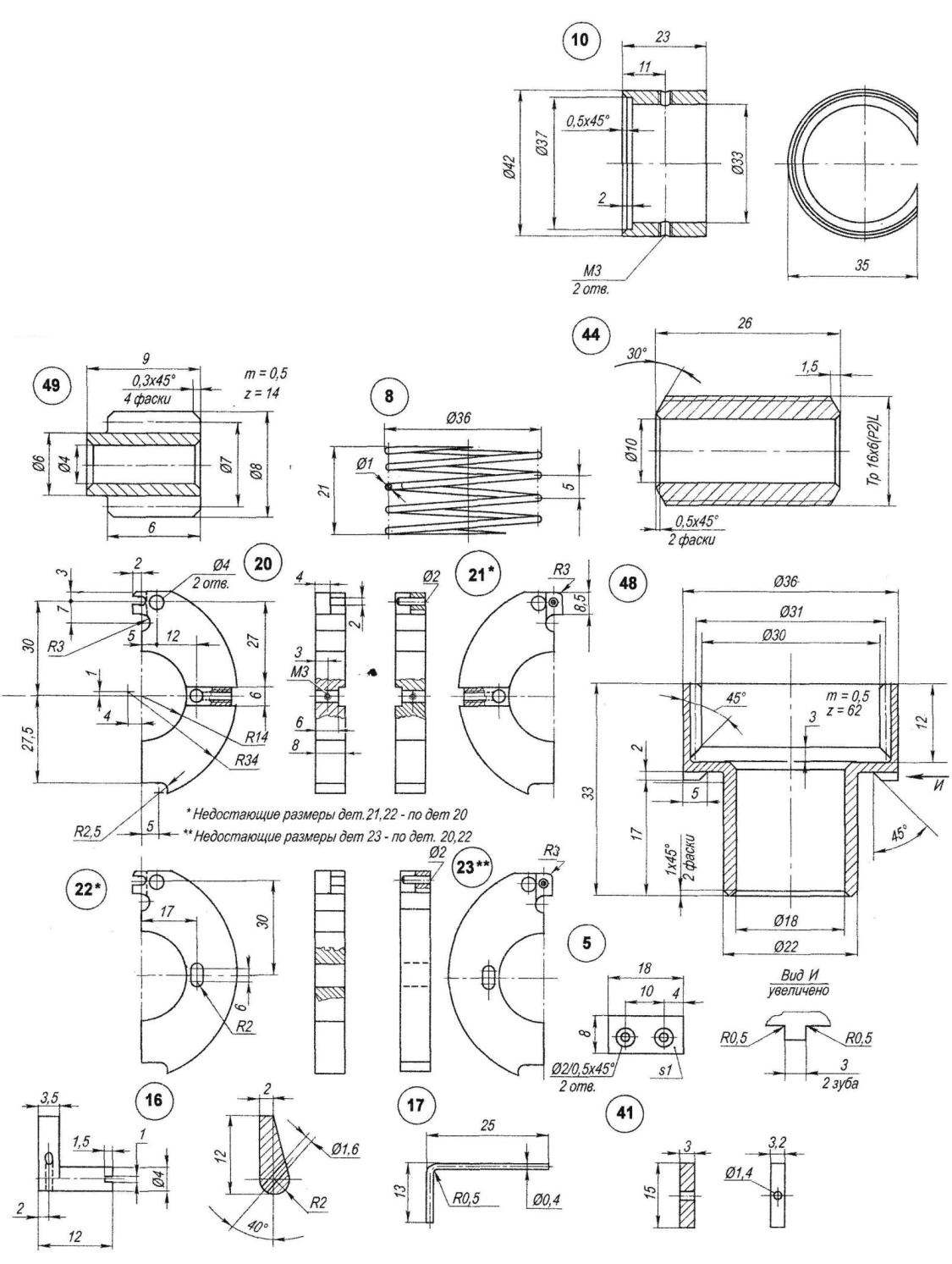
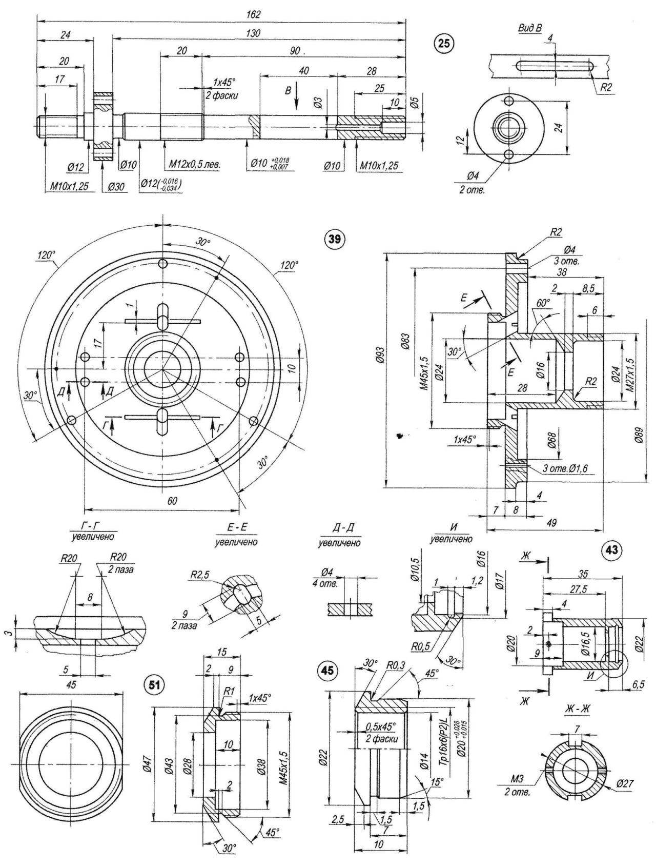
Fig. 2. Multi-speed hub with automatic gear change:
1 —spoke wheel (36 PCs); 2 housing bushings (steel 45); 3—elastic part of the key (rubber); 4—rivet (St3, Ø2. 5,2); 5—dowel (steel 45, sheet s1); 6—the control ring (45 steel); 7—threaded coupling z=34, m = 0,5 (45 steel); 8—spring (wire Ø1); 9—peg with thread M3 of glass (steel 45,2 PCs.); 10—Cup(St3); 11—thrust (cord thread Ø1, 2 pieces); 12—unit (St3, 2); 13—axis of the target (wire Ø1, 2); 14—a large ball bearing Ø4 (12 PCs); 15—separator large bearing (St3); 16—dog (steel 40X, 3pcs.); 17—spring dog (wire Ø0,4,3). 18—pen fork of the bike; 19—attachment of the sinker (М2х4 screw,2 PCs); 20—lead sinker with a keyway (45 steel); 21 —a lead sinker with a boss (45 steel); 22—slave weight with a keyway (steel 45); 23—slave weight with a boss (steel 45); 24—hub with a block of asterisks; 25—the axis of the rear wheel (steel 45); 26—nut M 10×1,25 (steel 40X, 2); 27—nut fastening braid of the cable M10x1,25 (steel 40X, corrugated surface); 28—cable Ø2,5 in budenovskoy braid; 29—inner cone small bearing (SHKH15, 2); 30—ball small bearing (8×2). 31 separator small bearing (St3, 2); 32—nut zacharenia the inner cone of the middle bearing (steel 45, range 35); 33—the inner cone of the middle bearing (SHKH15, round 34); 34—ball bearing medium 04 (8 PCs); 35—separator of the middle bearing (St3, round 38.5 cm); 36—the axis of rotation of weights (steel 40X, 4x); a 37—M3 screw mounting to the hub of the ratchet block stars (12 PCs); 38—ratchet (steel 45, range 80); 39—the hub (steel 45); 40—pin (steel 40X, the range of 4,2 PCs.); 41 —plank (45 steel); 42—biscuit (St3, round 16) with locking ring (wire Ø1); 43—sleeve Executive level (45 steel); 44 threaded bushing Tr16x6(p2)L Executive elements (steel 45); 45 —nut Tr16x6(p2)L Executive elements (steel 45); 46—thrust washer reverse halves of the coupling; 47—snap ring pinion; 48—reverse coupling z = 62, m = 0,5 (45 steel); 49—pinion z = 14, m = 0,5 (45 steel); 50—pinion (steel 45,04, 2 units); 51 —cap sleeve (steel 45, range 60); 52—the outer cone small bearing; 53—nut M10x1,25, left (steel 40X, range 25, 2 PCs.)
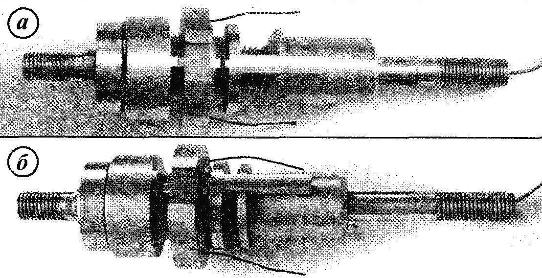
The links of the mechanism automatic speed switch, mounted on the axis of the rear wheels:
a — ring is in neutral position, b — ring is engaged with threaded coupling
The whole mechanism of the automatic shifting (change of torque) placed in the housing sleeve on a stationary axis of the driving rear wheels. Conventionally, the mechanism can be divided into several parts: defining, controlling, regulating, executing, and switching, although the latter is outside the sleeve. The conventions about the division have to mention because it’s still a solid mechanism and the edge parts of adjacent links can be rightfully attributed to the previous and to the next level.
Specifies the link consists of a hub 39, four polukoltsami weights 20,21,22, 23, the two flexible rods 11 (connecting the weights with the control ring 6), the decompressed normal return spring 8 and Cup 10, which rests on a spring, and pins. Key component: contains an elastic part 3, rubber and hard steel—5. Fixed dowel on the housing sleeve 2 by two rivets 4.
Weights can be divided into pairs: the leading 20, 21 and slaves 22, 23. Each of the weights hung on its axle 36. The axis is pressed into the hub 39 with diametrically opposed from the center of the sides in two pieces. While the slave and host weights (also in pairs) joint pin 40, each of which is also pressed into the hole in the lead weight. In guided-weight of the pin is made oval groove. Together with the rotating sleeve 2 and the hub 39, the weights move apart under the action of centrifugal force or again move under the action of return spring 8 by reducing the speed of rotation of the wheel.
The governing body consists of the control ring 6 with a slot for the dowel and two half-couplings: threaded 7 and reverse 48 satellites 49. Threaded half-coupling on the right of its parts (from the block stars) has the form of a two-horned forks, and the left side is cylindrical. In this part of the coupling has an internal left-hand threads M 12×0,5 and screwed onto the axis with the same external thread.
The reversible coupling 48 is made in the form of a two-stage cylinder. The right side of the half-coupling mounted on a threaded half-coupling freely, and the left—through two satellites. For this, both coupling halves sliced the corresponding teeth with the module t = 0.5 mm: threaded on the outside, and the reverse — from the inside. The satellites provide the possibility of reverse rotation of the reversible coupling half relative to the threaded that enables to switch the speed from a higher to a lower. Management provides consistent switching speeds with the lowest to the highest, and back, as well as a clear mechanism.
The Executive branch consists of a threaded sleeve 44 pressed on the axis 25 with a diameter of 10 mm, the nut 45 and planted her with an interference fit on a diameter of 20 mm (in the Assembly process of the sleeve) the sleeve 43.
Sleeve and nut are threaded Тг16х6(P2)L—trapezoidal left-start with a step of 2 mm, only the sleeve is exposed and the nut is internal. While the Executive branch has constant communication with the movable control element via a plug threaded coupling half 7, which is in the grooves of the rim of the sleeve.
Switch link consists of a cable 28 and a conventional carriage of a multi-speed bike. The cable is connected with the casing of Executive managers by means of straps 41 and 42 of the biscuit with the lock ring. Strap is moved to the groove axis, while the sleeve 43 slides along its surface.
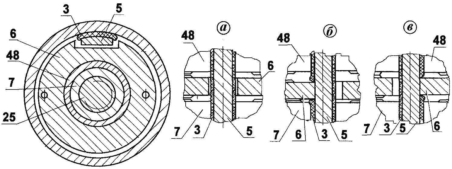
Fig. 3. The scheme of movement of the control ring 6 relative to the dowel 3.5, with switching speeds (item numbers coincide with Fig.2):
a—neutral position (the teeth of the control ring 6 and the coupling halves 7 and 48 are not geared and have the clearance); b—tooth of the control ring 6 is engaged with a clove threaded half coupling 7—switches to higher speed; the kink of the control ring 6 is engaged with reversible clove halves of the coupling 48 is switched to a lower speed
The carriage moving drive chain as on a normal multi-speed bike, but only sequentially from one sprocket to the next.
By the beginning of the movement the sleeve elements are in the position shown in figure 2. The circuit is thus draped over the largest sprocket, and between the teeth of the control ring 6, threaded half couplings 7 and the reverse hub 48 are small gaps (about 0.5 mm).
With the beginning of movement in the housing sleeve 2, and along with it the hub 39 and weights 20-23 start to rotate with the wheel. The case 2 through a key 5 causes the spin and the control ring 6.
With increasing speed under the action of centrifugal force weights 20-23 are starting to slide and pull through 11 act on the control ring 6, forcing him to move to the right (in the direction of the block of asterisks). With the gap between the teeth of the control ring 6 and threaded half coupling 7 is removed, the teeth are engaged (literally 0.5 mm) and screw coupling half 7 is rotated one revolution and moves on a single turn of the thread (pitch 0.5 mm) axis 25. The very same control ring at this time, the groove wall abuts the elastic rubber portion 3 of the dowel (Fig. 3b) and due to the friction against her cease to move along the axis. The teeth of the ring 6 and the hub 7, after rotating one turn out of gear, stopping the rotation of the threaded half-coupling (which happens at the end of the operational cycle speed).
During contact of the teeth of coupling half 7 through the plug, inserted in the grooves of the sleeve 43, makes it along with pressed into her nut 45 to rotate one revolution. When this happens move to the Executive level along the axis on the right trapezoidal thread on one move (for the start of the thread on the 3 steps, that is, 6 mm).
At this point, stretched the cable 28 acts on the gear shift (it staffing and not illustrated), and that, in turn, throws the chain on the next (smaller) sprocket. With further increase in speed, the cycles are repeated until then, until the chain will not appear on the smallest sprocket—the cyclist will be moving at maximum speed.
When you slow down, the weights will begin to converge, the thrust to weaken and the control ring 6 under the action of the spring 8 will shift to the left until gear reversible coupling 48, causing it to turn. Thus the reversible coupling half turn threaded coupling half 7 (but in the opposite direction than when accelerating), which, in turn, will be forced to rotate also in the opposite direction and move to the left the sleeve 43 and a nut 45. Last detail, pull through strap 41 for the rope and will cause the switching mechanism to shift the chain on the big sprocket. The cyclist thus can overcome the climbs, while not increasing effort on the pedal and the speed of their rotation. Switching cycles at low speed are repeated until the stop of the Bicycle.
Each shifting speed occurs in a strict sequence that is illustrated graphic material presented on figure 3.
In conclusion, some recommendations on technology of manufacture and Assembly.
Procurement of parts from steel 45 should be improved (hardened and tempered) to 35-42 HRC.
In the process of assembling the mechanism the friction surfaces of parts must be lubricated with grease.
The position of the Cup 10 (and, therefore, the preliminary spring tension) the master link is adjustable before the trip with the help of pegs 9, depending on the physical capacities of the cyclist. To do this, press simultaneously on both peg with your fingers and move the glass to the desired position. When you release the pegs samosogrevaetsya glass again in the body of the sleeve. If the cyclist is young and full of energy, the Cup moves further away from the block of stars, and Vice versa.
V. ALESHIN, design engineer
Recommend to read
 THE CREATORS OF “FIRE ARROWS”
The emergence of missiles in Russia noted by the chroniclers in the Pskov chronicle of the XV century In 1680 in Moscow organized a special "school" for the production of lighting and... “COMBINE” SOLDERING IRON
A good soldering iron stand is necessary for the radio Amateurs and all those who deal with soldering. Description of just such a fixture and is offered to attention of readers. The...
