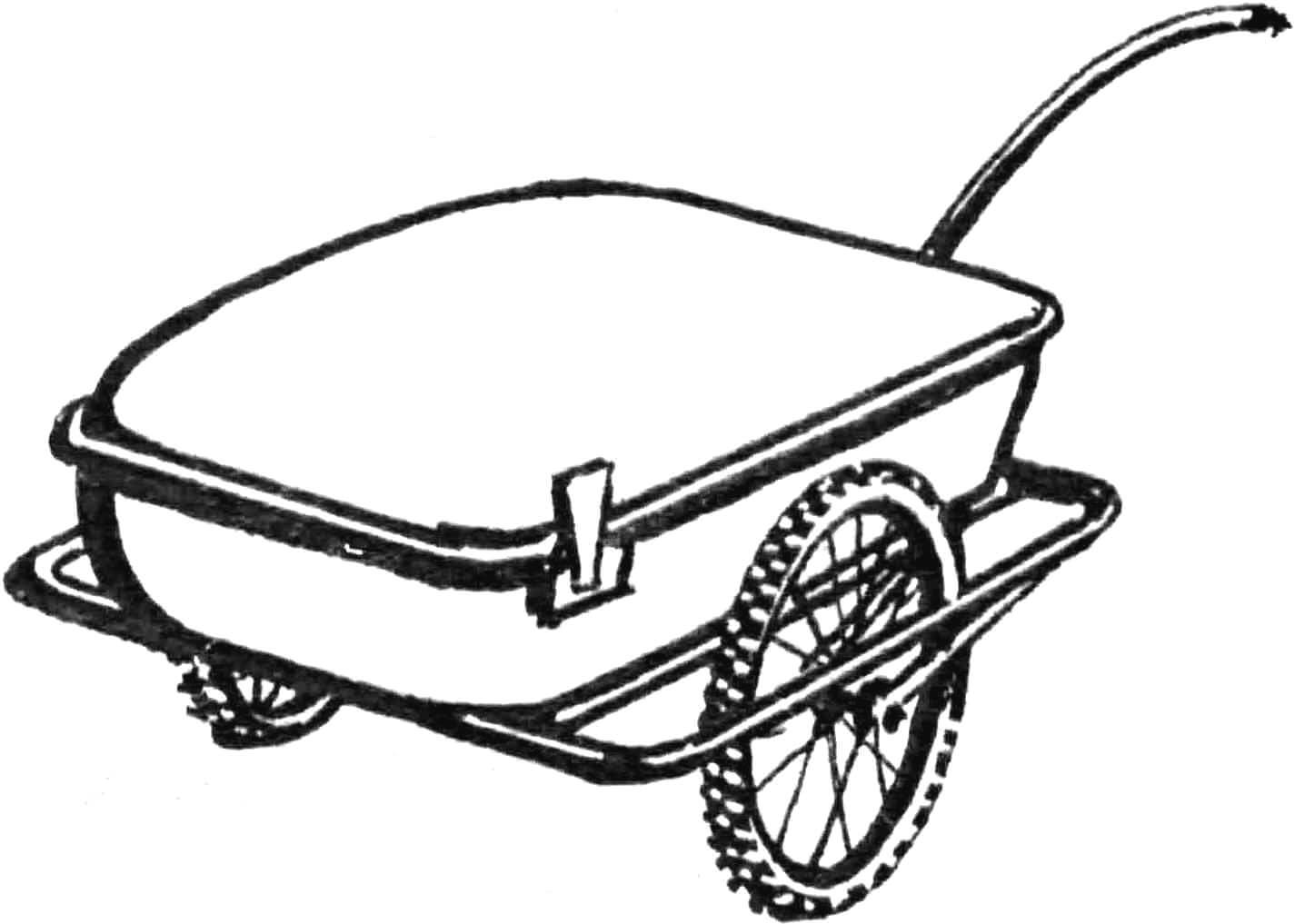
For more than a year, Stepan Ivanovich Gorshkov has been perfecting the bicycle design. His efforts, however, are not aimed at achieving high speeds. No! Let the racers do that! Comfortable seating while riding, easy transportation on trains — that’s what his efforts are aimed at.
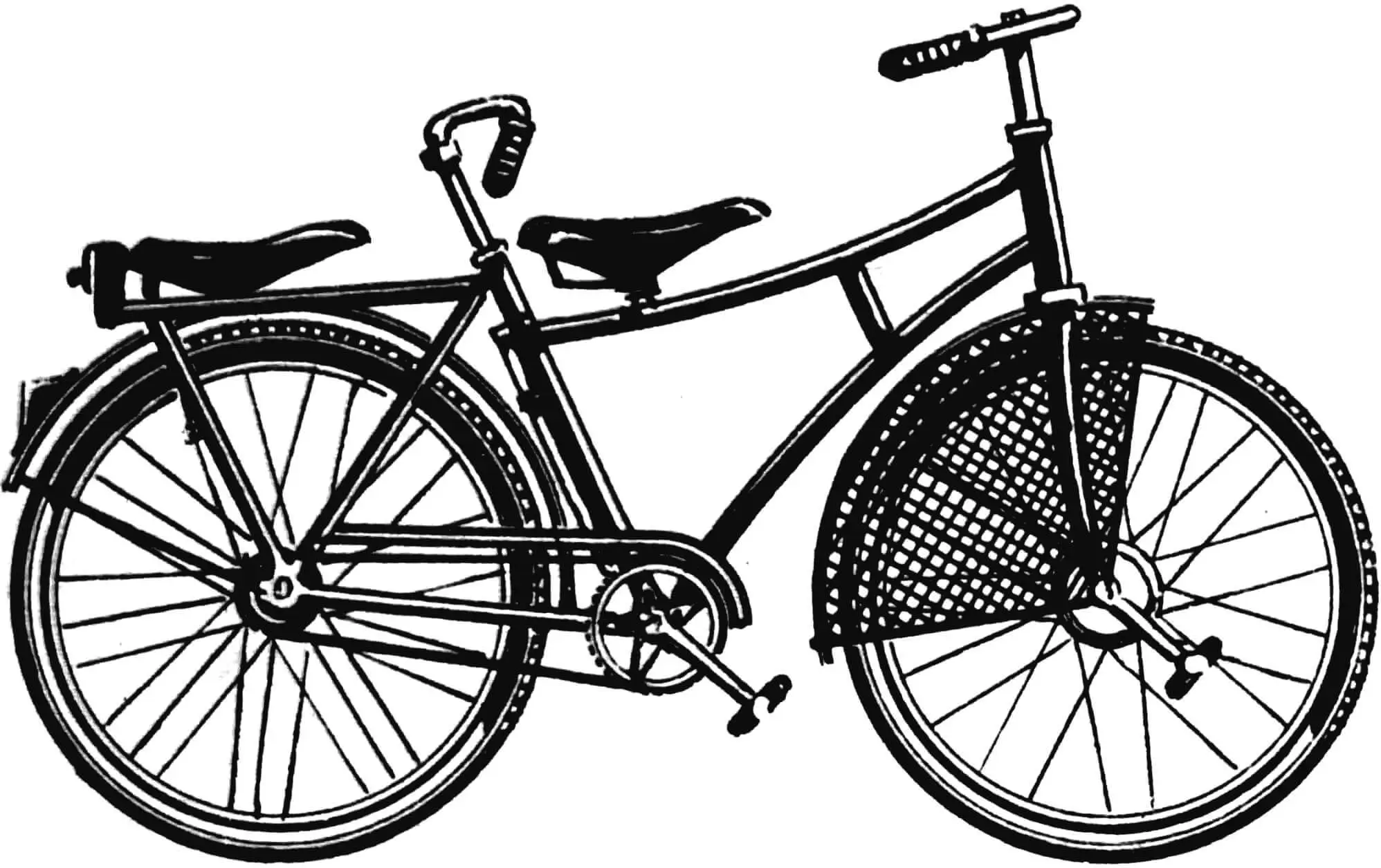
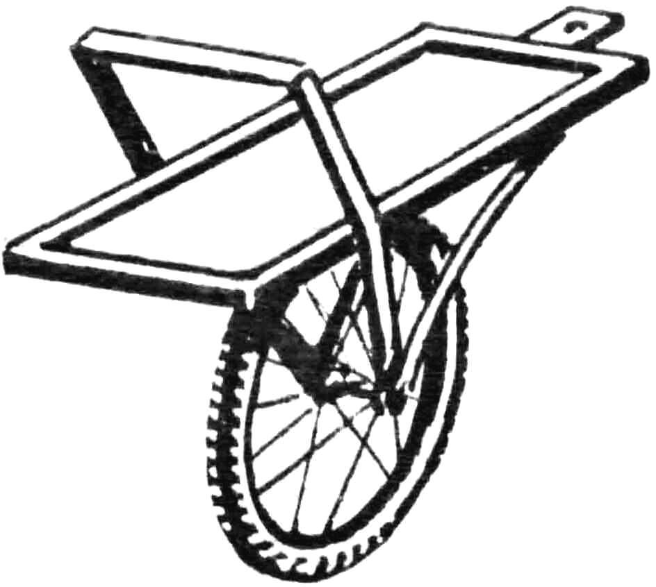
The main principle of all improvements by S. I. Gorshkov: the cyclist should sit comfortably. Usually, a person riding a bicycle strongly leans the body forward, transferring almost all of its weight to the arms. Such a position is justified when riding racing bicycles, where it’s important to reduce air resistance. In tourist trips, you won’t last long in this position. And can you really observe the surroundings when you’re lying almost horizontally? It would be much more convenient to sit in the saddle like on a chair, but… The bicycle design must be changed for this. The handlebar needs to be raised up and brought closer to the saddle so that, sitting upright, you can reach it with semi-bent arms, and the pedals moved forward, under the handlebar. All this is possible by reducing the diameter of the rear wheel, which lowers the saddle, and applying a drive to the front wheel. The lowered saddle has another advantage: when stopping, you can rest on both feet at once.
This does not mean a return to the bicycle of the beginning of the century with a front wheel almost as tall as a person. That one had such a large wheel due to the use of direct drive. Gorshkov’s bicycle, however, has a transmission where with each revolution of the pedals, the wheel makes 2.25 revolutions. Therefore, a front wheel of conventional size can be used. Such a design was created by Stepan Ivanovich (see fig.).
The basis was a women’s road bicycle. The missing parts were mainly selected from the spare parts department of the store and modified.
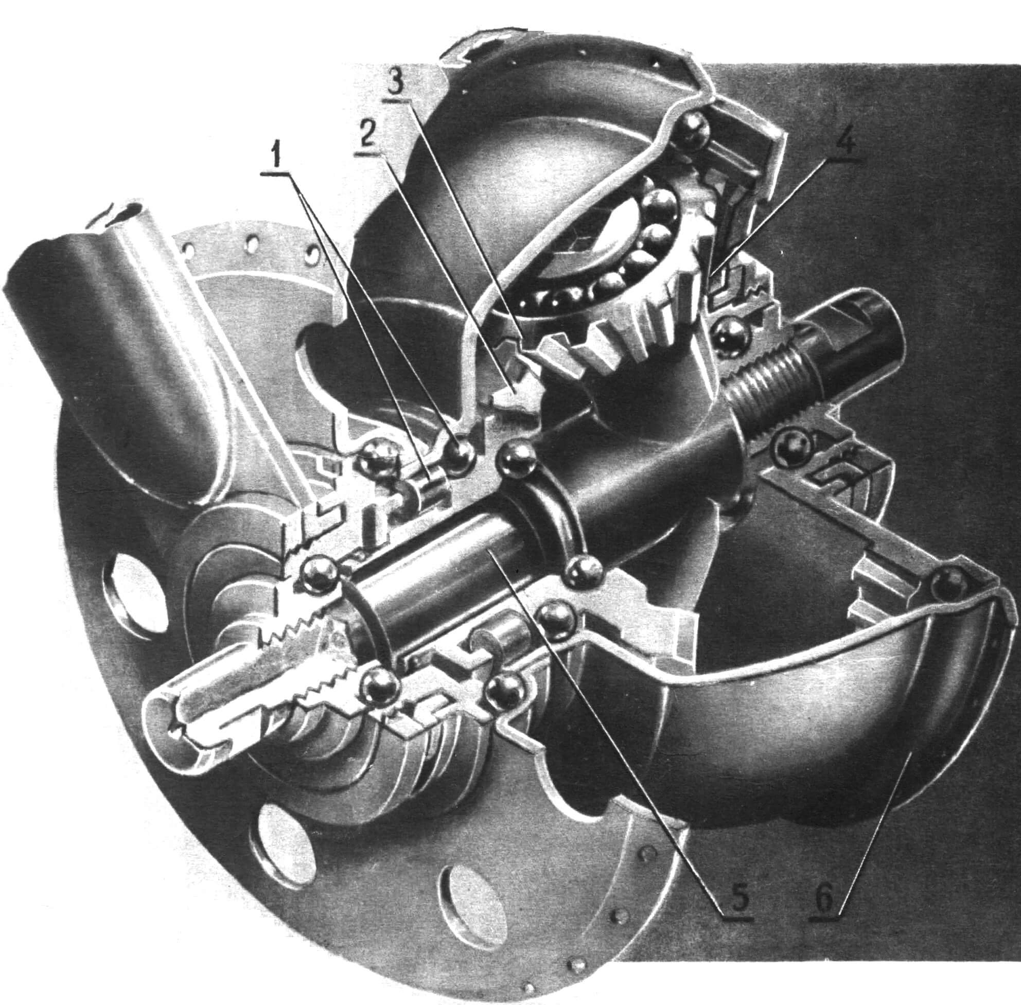
The stationary gear 4, rigidly connected to the wheel fork, is the bearing housing in which the bottom bracket axle 5 is installed. Two satellite gears 3 rotate freely on the axle projections. The driven gear 2 rotates freely on the bottom bracket axle and carries the braking and freewheel mechanism, the same one that is installed on bicycles with a brake hub. On freewheel, the rollers 1 roll into recesses on the gear housing 2, without touching the hub housing 6. During the working stroke and braking, the rollers are pulled outward and stand spread between the gear and the hub, rigidly connecting them.
Chain transmission mechanism. The most unusual thing in this bicycle is the front wheel. It determines the design solution. The bottom bracket axle, on which the pedals are fixed, is here coaxial with the front wheel hub, so the chain transmission is made with a parasitic double sprocket with two chains. The torque is transmitted first to the parasitic sprocket, and then from it — to the wheels. Each stage has a ratio of 1 : 1.5, and the total gear ratio is 1.5X1.5=2.25.
The front wheel hub has become more complex, there is no room left in it for the freewheel mechanism, and it was moved to the parasitic sprocket. This is one of the few disadvantages of such a system: on freewheel, one of the chains (driven) is constantly in motion.
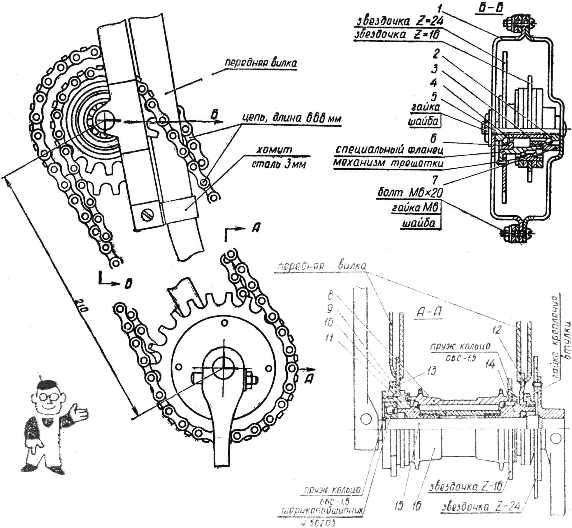
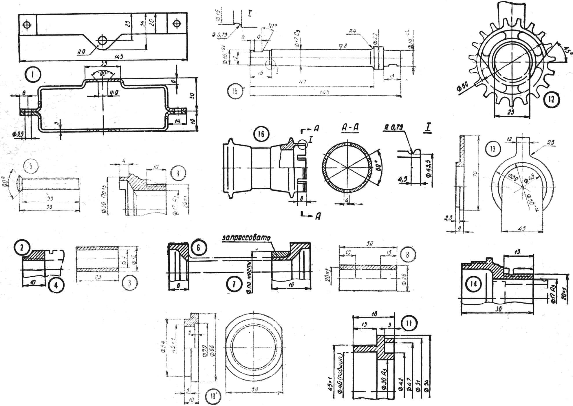
1 — housing; 2, 4 — cones; 3 — spacer tube; 5 — axle; 6, 7 — bearing housings; 8 — spacer tube; 9, 14 — cones; 10 — nut; 11 — bearing housing; 12 — right dropout; 13 — left dropout; 15 — bottom bracket axle; 16 — hub housing.
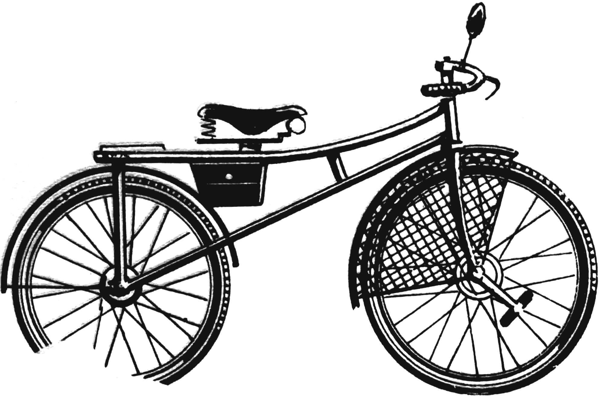
The frame (Fig. 1) of a women’s road bicycle was cut at the bottom bracket assembly, and both parts were rotated around the cut point so that the lower tubes form a straight line when viewed from the side. All four stays of the rear fork were preliminarily shortened by 100 mm so that it would correspond to a wheel from “Orlyonok” with a diameter of 24″. Before welding, tube segments, 100 mm each, were inserted into the frame tubes. The ends of the front fork were cut off, and new dropouts for the front hub were welded in their place. The axle position should remain the same. The right dropout according to the drawing is not difficult to make from the driven sprocket of the brake hub, cutting off everything unnecessary from it. The left one 13 is made from scratch.
Front wheel hub. The front wheel now has a dual function: it has become the driving wheel and carries the bottom bracket axle. Therefore, its hub consists of three main parts: a hollow (load-bearing) axle, a bottom bracket axle rotating inside it, and the actual wheel hub housing, located on the outside.
The front wheel is almost entirely made from the rear wheel of a road bicycle with a brake hub. The hollow axle (stationary part) is assembled on modified cones 9 and 14 of the hub. The cones are connected to each other by a spacer tube 8, the length of which must be maintained quite accurately. It’s better to make it first with an allowance of 2—3 mm and file it in place so there’s no play in the bearings.
The hub bearings remained the same, except for the left one, a ball bearing in a dustproof design (No. 50203). This bearing is fixed on the axle with a spring ring made of OVS wire Ø 1.5 mm. Its housing has a groove that creates a dust protection labyrinth together with the hub housing.
The bottom bracket axle 15 is made from any case-hardening steel. The driving sprocket (24 teeth) is attached to the crank in any way. It’s desirable to get a right crank with a flange to which the sprocket is riveted or installed on screws. Then replacing it won’t be difficult. If the old sprocket is swaged on the crank, then it needs to be cut to Ø 70 mm, turning it into a flange, and then attach the new one to it.
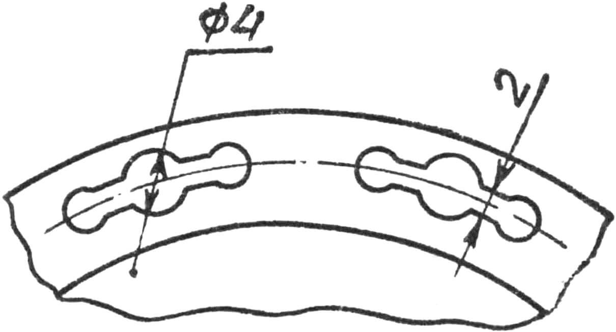
A driven sprocket (16 teeth) from a “Tourist” bicycle is attached to the hub housing. It’s better to make it removable so that after the final modification it’s easier to install the spokes. This can be done by mounting the sprocket on splines (the same as on the “Tourist” gear shifter). Its hole is bored to the outer diameter of the hub, but the splines are left. In the hub 16, grooves are cut under them. The sprocket is fixed with a spring ring or clamp. In case of “dead” mounting of the sprocket (welding, riveting, etc.), additional holes must be made in the hub for installing spokes (Fig. 3).
The front hub is attached to the fork with two nuts. One of them secured the driven sprocket and remained unchanged, the other — 10 — is made from scratch.
The freewheel mechanism is moved to the front fork. The parasitic sprockets are mounted on it. To make the mechanism, a non-brake hub of the rear wheel from a “Tourist” bicycle is used. Its axle 5 is shortened to 55 mm, and one of the ends is swaged. Instead of swaging, a washer 3—4 mm thick can be welded to its end. Installing a nut on the outside is undesirable (increases the overall thickness of the mechanism, which creates interference when riding). Cones 2, 4 and the hub housing are cut, and bearing housings 6 and 7 are obtained from the latter. Inside a special flange, which now becomes the freewheel mechanism housing, the bearings are assembled. A steel ring for mounting the special flange is pressed onto the right cone according to the drawing. The distance between the cones is set by spacer tube 3. The requirements for it are the same as for a similar part in the hub.
The ratchet mechanism is completely preserved, only the 16-tooth sprocket remains on it, the position of which is set by ring spacers. The 24-tooth sprocket is secured by riveting or on screws to a special flange. The entire device is assembled in housing 1, made from strip steel 3 mm thick, and attached to the fork with clamps 3 of the same material.
One chain from a road bicycle is sufficient for the entire transmission. The brake is rear, caliper type (from “Tourist”).
The rear wheel can have any non-brake hub. A front wheel from “Orlyonok” can be installed in its place.
V. PALYANOV
Recommend to read
 THE MOTOR IN THE ROLE OF TESTER
Among the devices that are used to check (continuity) of electrical circuits, not take samples. They are simple in design and application. The probe is an indicator, in series with which...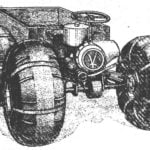 ALL FOUR LEADING
The vehicle is made according to the scheme proven by the tractor "Kirovets". He has the same "breaking" the frame and drive on both bridges. What gives? First, the permeability....
