 You can put on the car 4, 8… even 16 wheels. However, in the tundra, for example, even this machine will not work and kilometers. And no wonder that whole design teams engaged in the search for new propulsion, which would come to replace the wheel and provided all-weather cargo delivery, hauling of the forest, the work of the search parties… Already established for this purpose samples of tracked vehicles with very broad, almost 1.5 m tracks, snegokatov, hovercrafts.
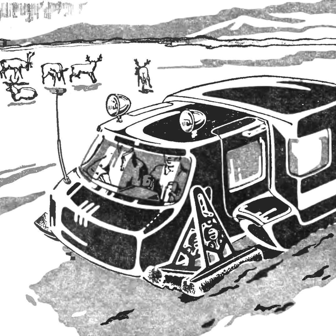
Not far behind in their quest for a creative and young technicians; and they offer the sometimes even more courageous decisions than those that are born in adult KB. One example of this model of thundergod “beetle”, presented at the “ideas Competition” young technicians Magadan suit. It bezusadochnye all-terrain vehicle, vehicle which is walked device.
Clicks the toggle switch, and a model that looks like a ladybug, quickly starts to touch the legs. It not only moves, but also overcomes various obstacles.
The model is based on two pairs of sectors. If you put them on a common axis, as is easy to see that moving forward can be produced in two ways — alternately rotating the sectors about the axis (Fig. 1) or moving them one after another, as if stepping (Fig. 1. In).
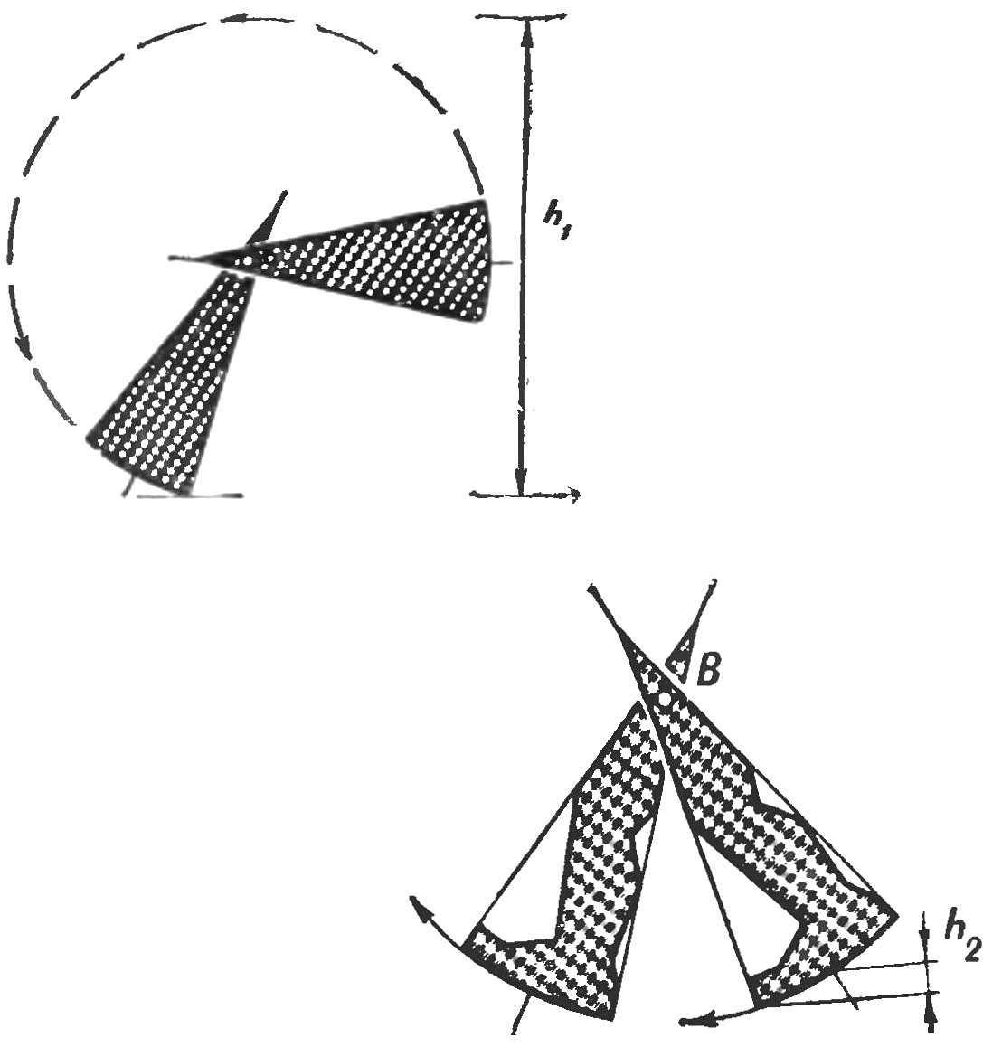
Fig. 1. The scheme of “walking” — moving sectors.
In either case, the work of wheels, in fact, replaced by just two sectors, that is to say, we are here to make wheels, get rid of the “extra” parts.
But the first method is less efficient, as the sector had been lifted above and, in addition, it would idle longer. Therefore the wise nature chose, for example, to move a person’s second method, suggesting that as the basic design of the knee and hip joints — a kind of hinges.
Back to our model. It is equipped with a special walking device having, in addition to the two pairs of sectors, even eccentric-rocker mechanisms. The eccentrics on the neck (Fig. 2) installed the ball bearings, the outer clips which are mounted in holes of the sectors.
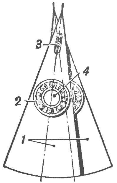
Fig. 2. Device sectors:
1 — sectors, 2 — bearing, 3 — fixed axis scenes, 4 — neck of the eccentric axle.
At the top of each sector has a longitudinal groove axis of the rocker mechanism. It causes the sectors to move along a certain trajectory, with the result that the model performs translational motion. The drive shaft eccentrics on the model can be carried out from the electric motor, powered from the mains or batteries.
To make the model move smoothly, without jumps, it is necessary to carefully calculate the size of the sector. This is done using a simple geometric construction.
CALCULATION OF SECTORS
Geometric construction gives the possibility to determine the size and shape of the reference Shoe sector. Thus we find a ratio of values of the radius of the eccentric, the height of the shaft above the support surface and removing from it the axis of the scenes.
Spend two mutually perpendicular axes XY and VD (Fig. 3). From point A, corresponding to the shaft center of the eccentric, down-delayed segment AO is equal to the radius of the eccentric. Up from point D lay off a line segment DC is equal to AO. Through the point parallel To the axis XY draw the line EP. On the horizontal axis, drawn through the point a, lay off the cut АО1 equal to the radius of the eccentric. From point b (corresponding to the position of the fixed AXIS scenes) draw a straight line through the point O1 to the intersection point M with the axis XY. The cut is OK, measured from the center O1 down the line VM and denote it by О1К1. Will ostavim a perpendicular from point K1 to the intersection point with the axis XY. Left and right point To put on the line EP cuts, equal K1L. Get the point e, and R, which are connected by the arc through the point D, resulting in a segment of the EDR. This will be the reference of the sector of a walking device, and the points R and E show the boundaries of the surface of contact.
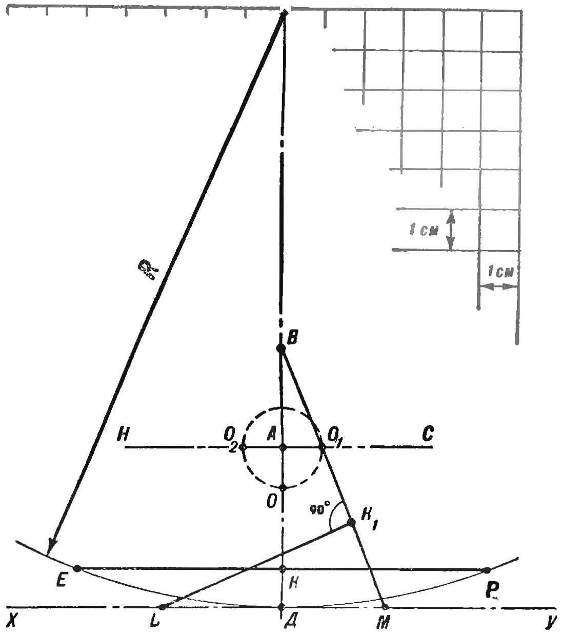
Fig. 3. The geometric construction of an arc to determine the linear dimensions of the sector.
To get a more accurate curve of contact, using the given method can find the intermediate point of the arc RE.
The size of the support surface, or arc length D, depends on the distance of the point A to the XY-plane of radius AO and the eccentric distance from the drive shaft And fixed to V. If you change any of these values, the size of the Shoe change. Therefore, the location of the axes and the radius of the eccentric must be chosen in dependence on the required length n of the height of the step of the propeller.
Recommend to read
 IF THE APARTMENT IS CLOSELY
They are large and small, foldable and "monolithic", table and floor - the different designs, but with one common shortcoming: require space for storage. We are talking about Ironing... WILD FLOWER GARDEN
Stationary flowerbed near the house or dacha good as long as it don't interfere. Move it if necessary — the whole problem. As shown in the figure — at any time and in any place. Because...
