A familiar winter TV story is the rescue of ice-fishing enthusiasts from a drifting ice floe. Almost every year we are shown how emergency services specialists on helicopters, boats, or all-terrain vehicles save unlucky anglers.
Such incidents are not uncommon on the country’s freezing bodies of water. Moreover, anglers often drive out onto the ice even in cars, risking every minute of falling through and losing, if not their lives, then at least their vehicles.
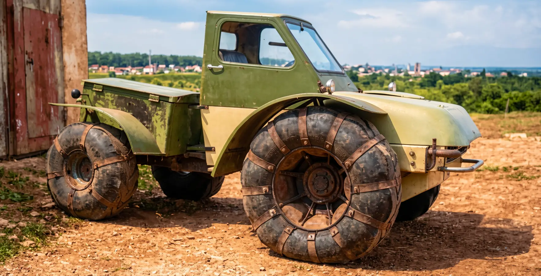
I go fishing too, and not only in summer but also in winter. However, unlike other enthusiasts who like to sit over a hole with a rod in their hands, I am almost certainly safe from trouble. My vehicle will not only not sink, but is also unlikely to break through the ice. That is why I built an all-terrain vehicle — so it would take me not only to the water but also back home.
To be honest, this is my second pneumatic vehicle. The first was larger and more spacious (a description of its design was published in the magazine “Modelist-Konstruktor” No. 1’2000. — Ed.). It fully met my transport needs. Nevertheless, I had to pick up pencil and paper again, and then tools as well.
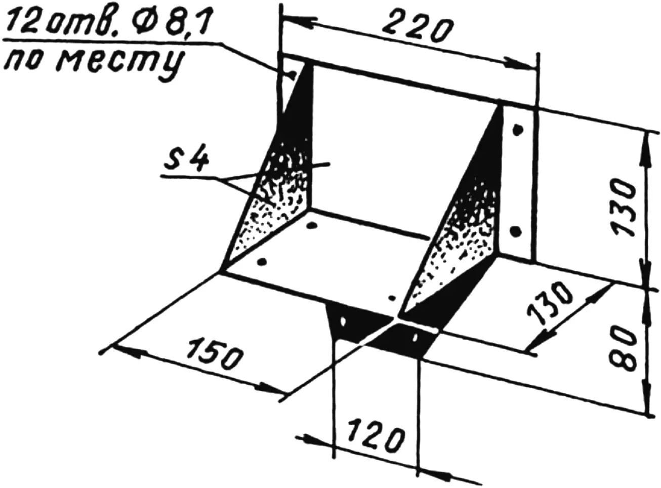
Rising fuel prices forced me to design and build a smaller, simpler machine. Compare: the large all-terrain vehicle burned six to seven liters of fuel on a fishing trip, while the small one used only three liters for the same route.
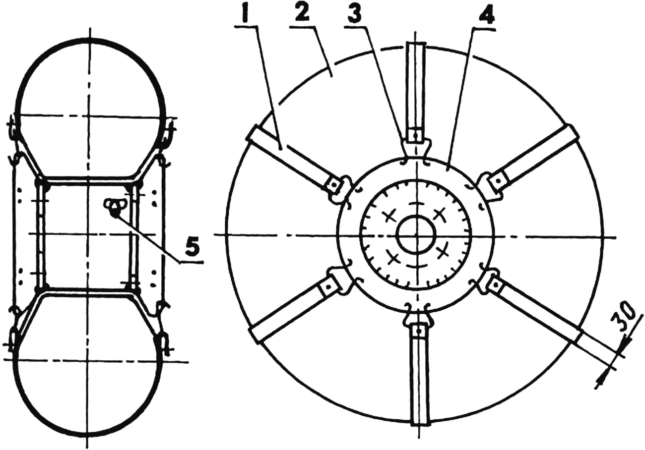
1 — tread band (rubber 30×5, 6 pcs.); 2 — pneumatic tire (two tubes 710×300); 3 — double hook; 4 — split disc; 5 — valve
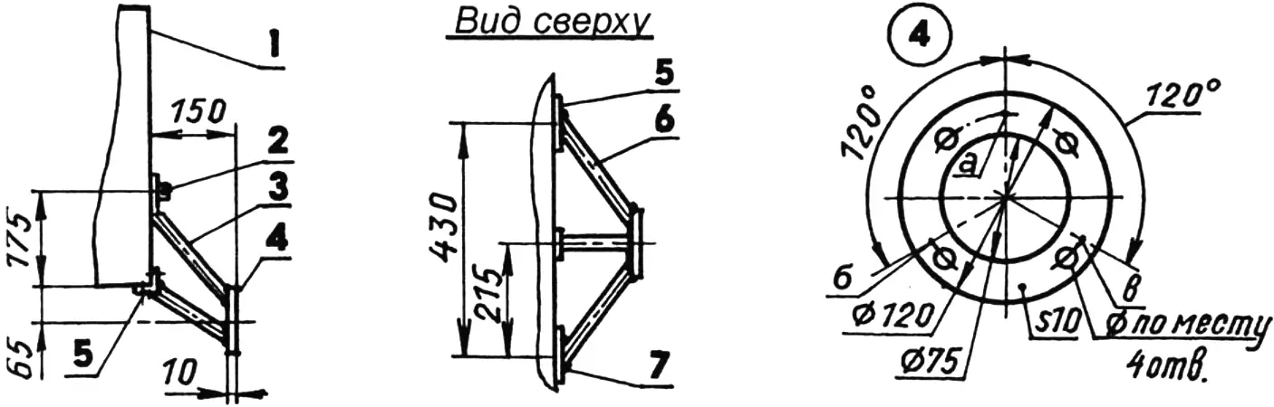
1 — body shell; 2 — M10 bolt; 3 — central brace (steel, tube 22×3); 4 — flange (steel, sheet 4s10); 5 — bracket (steel, angle 40x40x2, L100, 2 pcs.); 6 — side brace (steel, tube 22×3, 2 pcs.); 7 — M8 bolt (8 pcs.);
on part 4, points a, b, c indicate brace welding locations
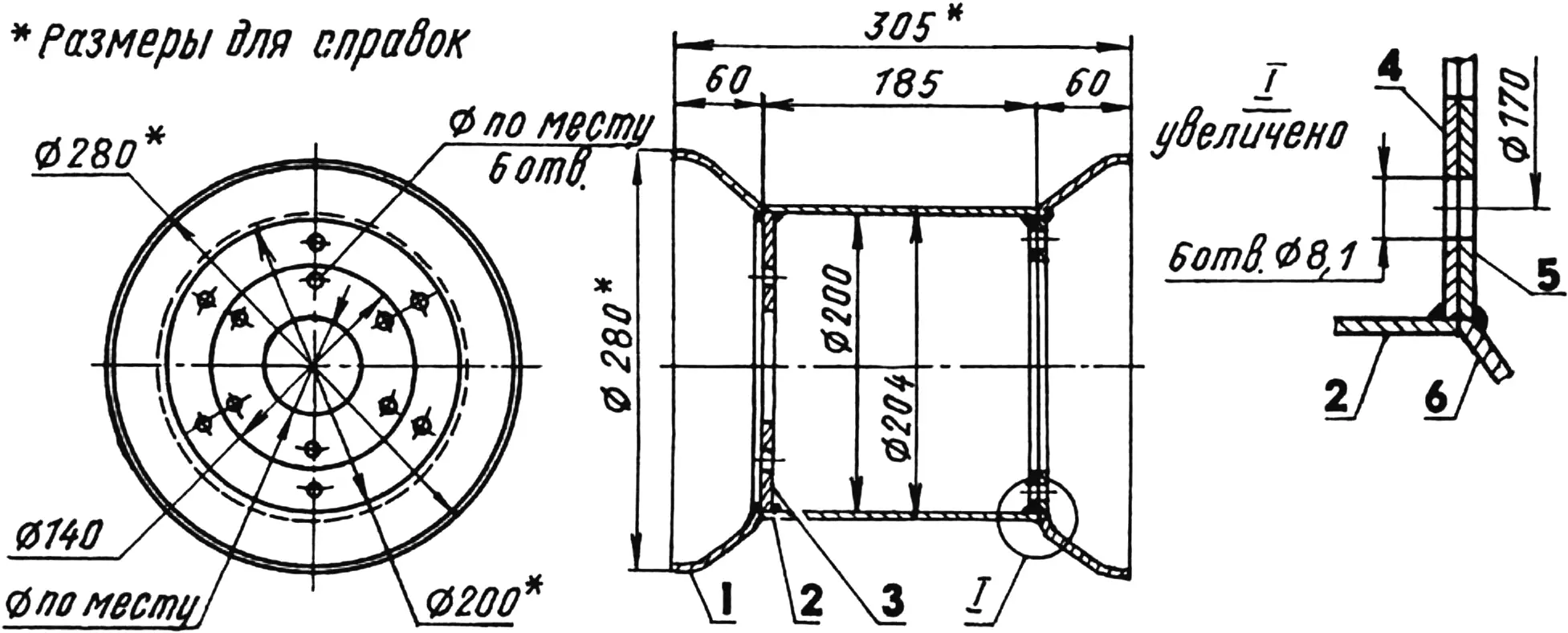
1 — welded half of wheel disc (from “Zaporozhets”); 2 — drum shell (steel, sheet s2); 3,4 — drum ends (steel, sheet s2); 5 — flange of removable wheel-disc half (steel, sheet s2); 6 — removable wheel-disc half (from “Zaporozhets”)
Moreover, the “little one” is unsinkable, since a sealed body and pneumatic wheels keep it afloat. In water it can move by rotating the front driving pneumatics. True, slowly (due to the small wheel-axis draft), but steadily. I tried attaching blades of various shapes to the front wheels, but found no noticeable speed gain. More effective propulsion would have required serious complication and added weight.
In the end I changed nothing and consoled myself with the thought that I need the all-terrain vehicle more for driving than for swimming.
Two years have passed since then. The vehicle is used quite intensively, yet I have no particular complaints about it. Its only drawback is the lack of reverse, which, however, is compensated by good maneuverability.
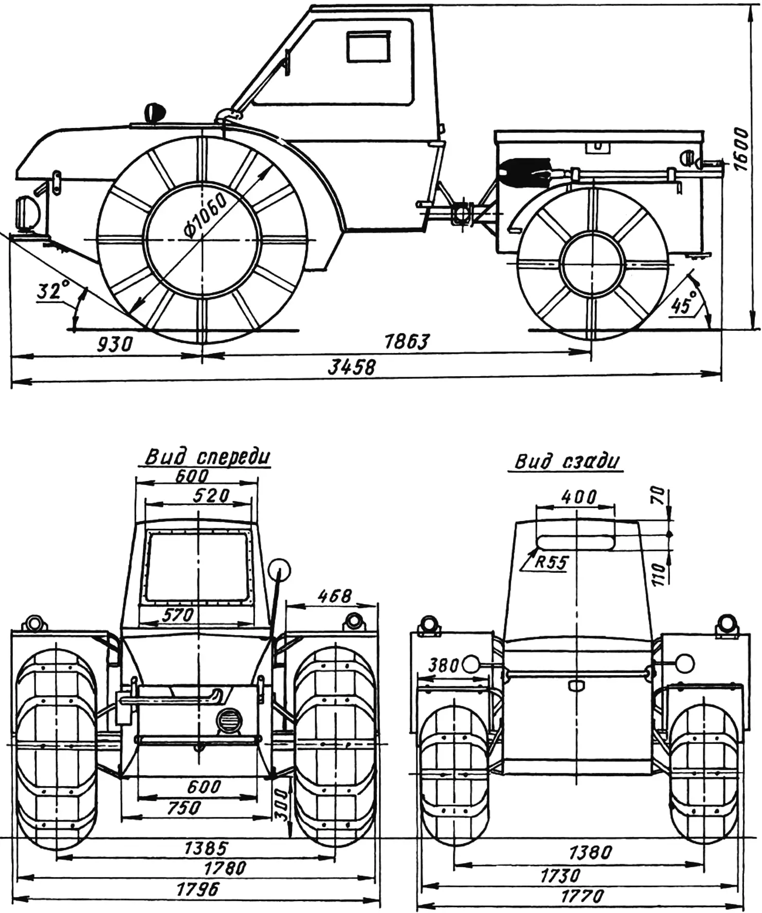
Vehicle weight is about 320 kg; maximum speed 40 km/h; fuel consumption is about 7 L per 100 km.
This is the design I submit for the judgment of readers of the magazine I respect. It uses many units from production vehicles without modification. A careful eye will notice on the drawings the absence of dimensions in places where these units are shown or where free gaps (at the builder’s discretion) are allowed between them. Let those who wish to build a similar design have room for improvisation, since everyone has their own stock of parts.
So, to make the new all-terrain vehicle use less fuel, I made it single-seat and fitted it with a 12 hp engine from a cargo motor scooter.
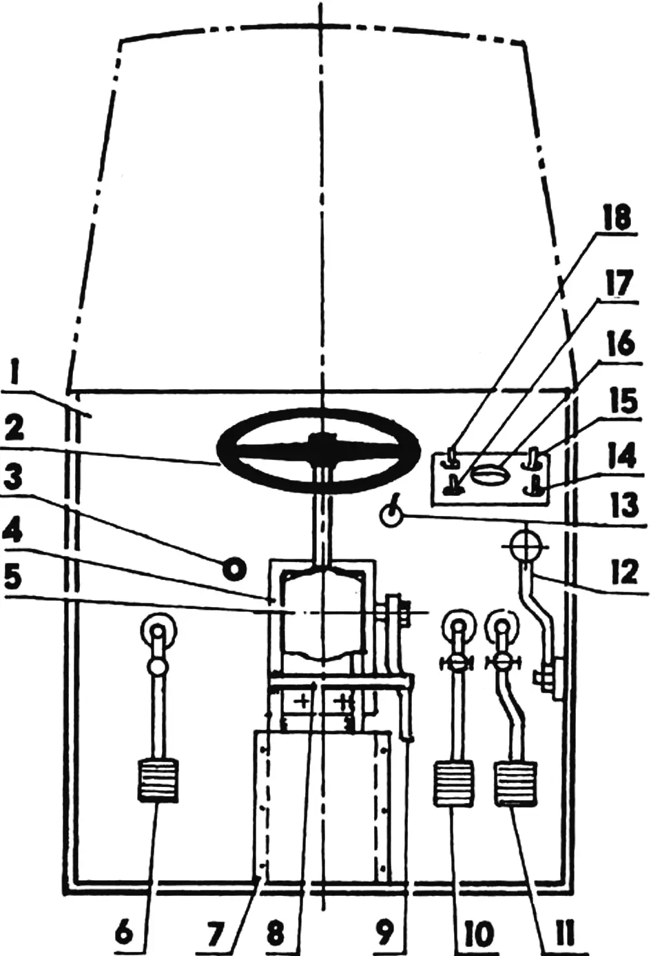
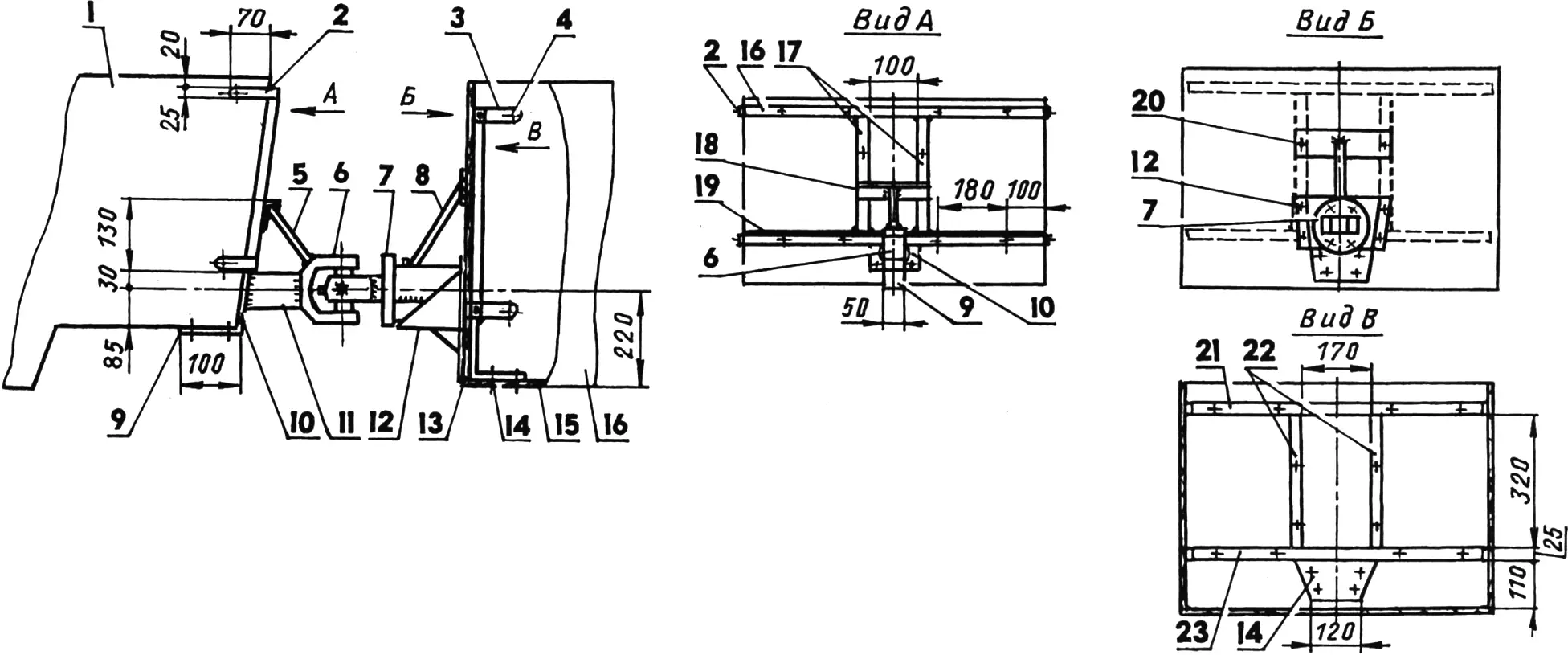
1 — cabin front wall; 2 — steering wheel; 3 — fuel-tank valve control rod; 4 — spatial bracket for steering mechanism mounting; 5 — steering mechanism; 6 — clutch pedal; 7 — front-wall cutout cover; 8 — steering pitman-arm rear travel limiter; 9 — steering pitman arm; 10 — brake pedal; 11 — throttle pedal; 12 — gearshift lever; 13 — carburetor air-flap control rod; 14 — turn-signal switch; 15 — headlights and marker lights switch; 16 — ammeter; 17 — dynostarter switch; 18 — engine stop switch
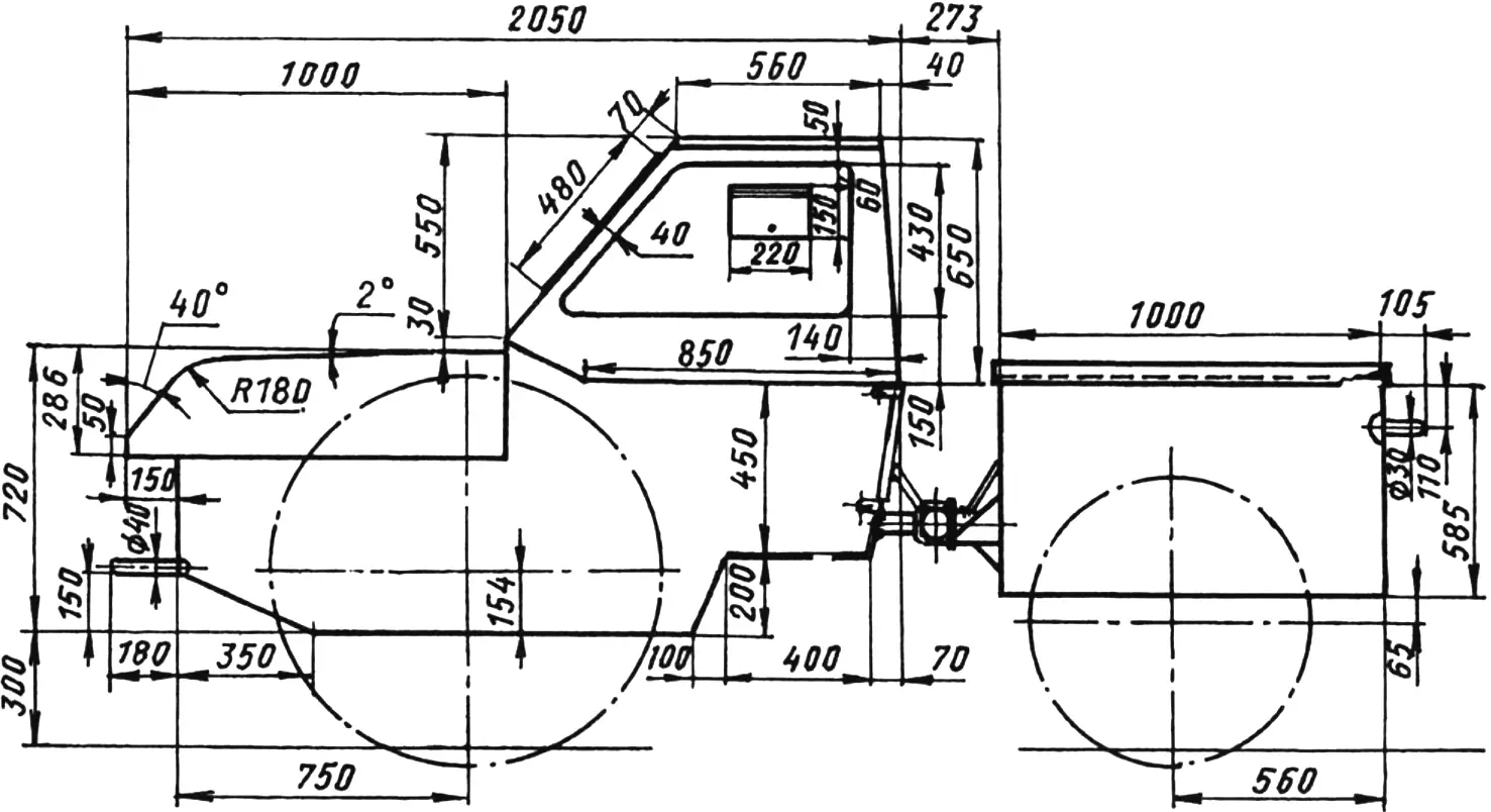
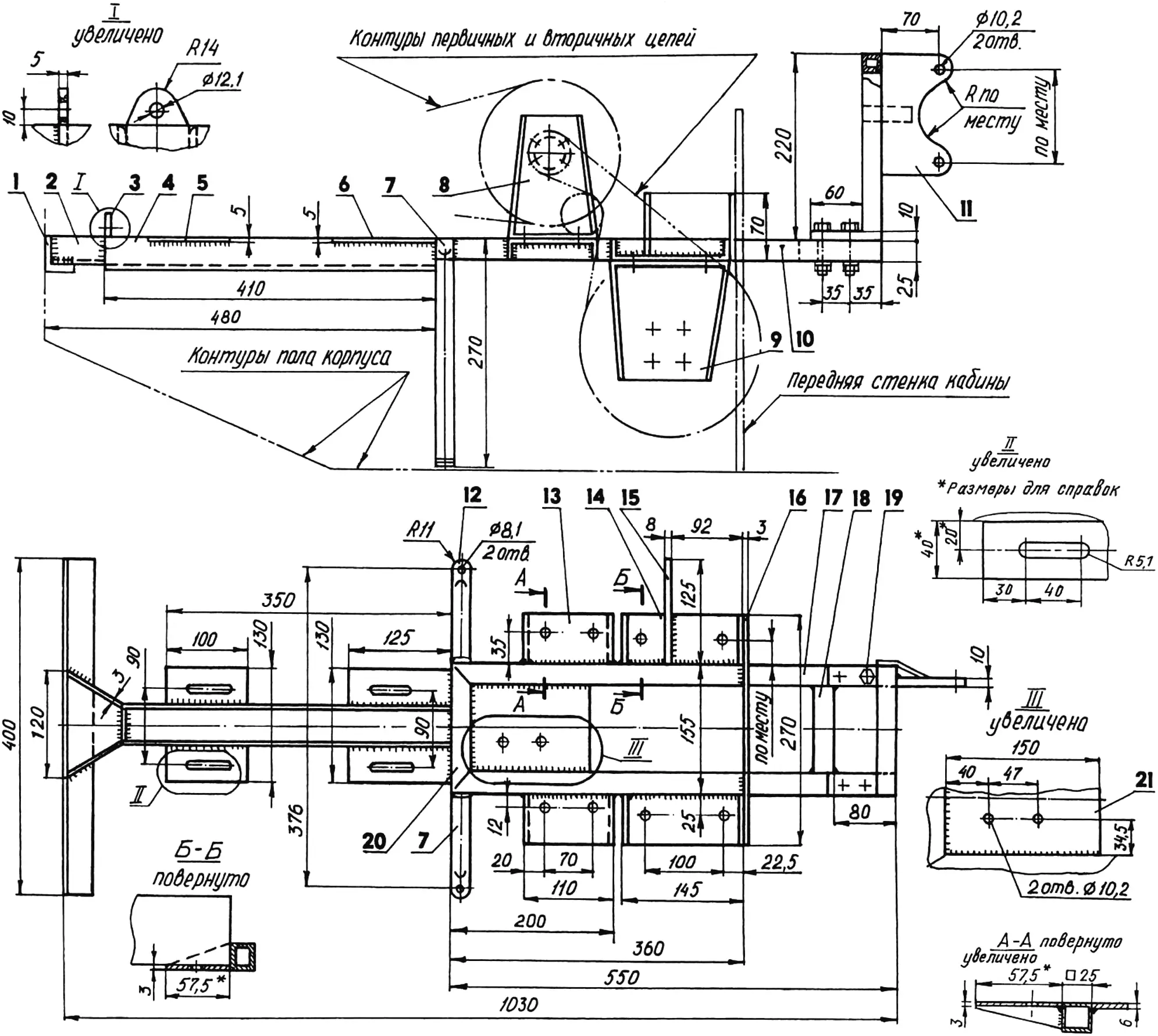
The vehicle has an articulated, i.e. two-part, frame. These parts, if separated, obviously cannot work on their own. However, for convenience of description we will conditionally call them tractor and body — by function.
The tractor and body shells are assembled from 12 mm plywood sheets on frames of aluminum angle 15x15x2.5 mm. Plywood sheets are riveted to the frames through rubberized fabric strips for sealing.
The hood, cabin top, body cover, and all fenders are made of 1 mm fiberglass. In summer the cabin top is removed, leaving only a windshield.
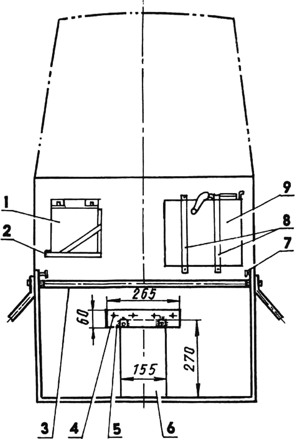
1 — battery; 2 — battery mounting shelf; 3 — under-hood brace for front-wheel suspensions; 4,5 — M8 bolt (4 pcs.) and transmission-frame mounting plate to front wall; 6 — front-wall cutout cover; 7 — left hood latch axle; 8 — fuel-tank band straps; 9 — fuel tank
In the tractor shell (mostly in the engine compartment and partly in the cabin) the transmission frame is mounted, welded from various steel profiles. At the front of the frame, so to speak, is a bumper made of steel angle, by which it is attached (with five M6 bolts) to the engine-compartment front wall. Between the bumper and the channel beam a channel-shaped adapter bent from steel sheet is welded. Four platforms for mounting the engine frame with the engine are located on the beam.
The frame then continues into a structure welded from square steel tube with flanges, on which two intermediate-reducer brackets (on top) and two differential brackets (below) are secured with M10 bolts. On this same part of the frame there are two more brackets: a plate type (welded) — for the master brake cylinder, and a spatial one (fastened with four M8 bolts) — for the steering mechanism from a “Zaporozhets” car.
1 — tractor shell; 2,3 — mounting hinges (steel, strip s4, 8 pcs.); 4 — M8 bolt (32 pcs.); 5,8 — supports (steel, rod 15×10); 6 — fork (part of ZIL car driveshaft); 7 — hinge unit; 9,14 — angle reinforcements (steel, strip s4); 10 — fifth wheel (steel, plate 110×90, s8); 11 — drawbar (steel, tube 60×5); 12 — bracket; 13,15 — body-shell wall and floor (plywood s12); 17,21,22,23 — coupling load-bearing elements (steel, tube 25×25); 18,20 — tractor support rest (angle 50×25); 19 — lower coupling load-bearing element (angle 35×35); 20 — body support rest (strip 50×8); 16 — body shell
In addition, two tubular support posts with flattened ends are welded to the frame for attachment to the engine-compartment floor (on the sides), and a plate for attachment to the cabin front wall (at the rear). All fasteners here are M8 bolts, two and five respectively.
Besides the engine, intermediate reducer, differential, master brake cylinder, and steering mechanism, the transmission frame also carries a secondary-chain tensioning device. For this the frame has a special platform with two holes.
At the bottom of the cabin front wall there is a 270×155 mm cutout. It was made so that when installing the transmission frame in the tractor shell, the spatial bracket for the steering mechanism at its end and part of the differential would end up in the cabin. After that the cutout was closed from the cabin side with a convex technological cover of galvanized sheet. The cover is removable — on six screws.
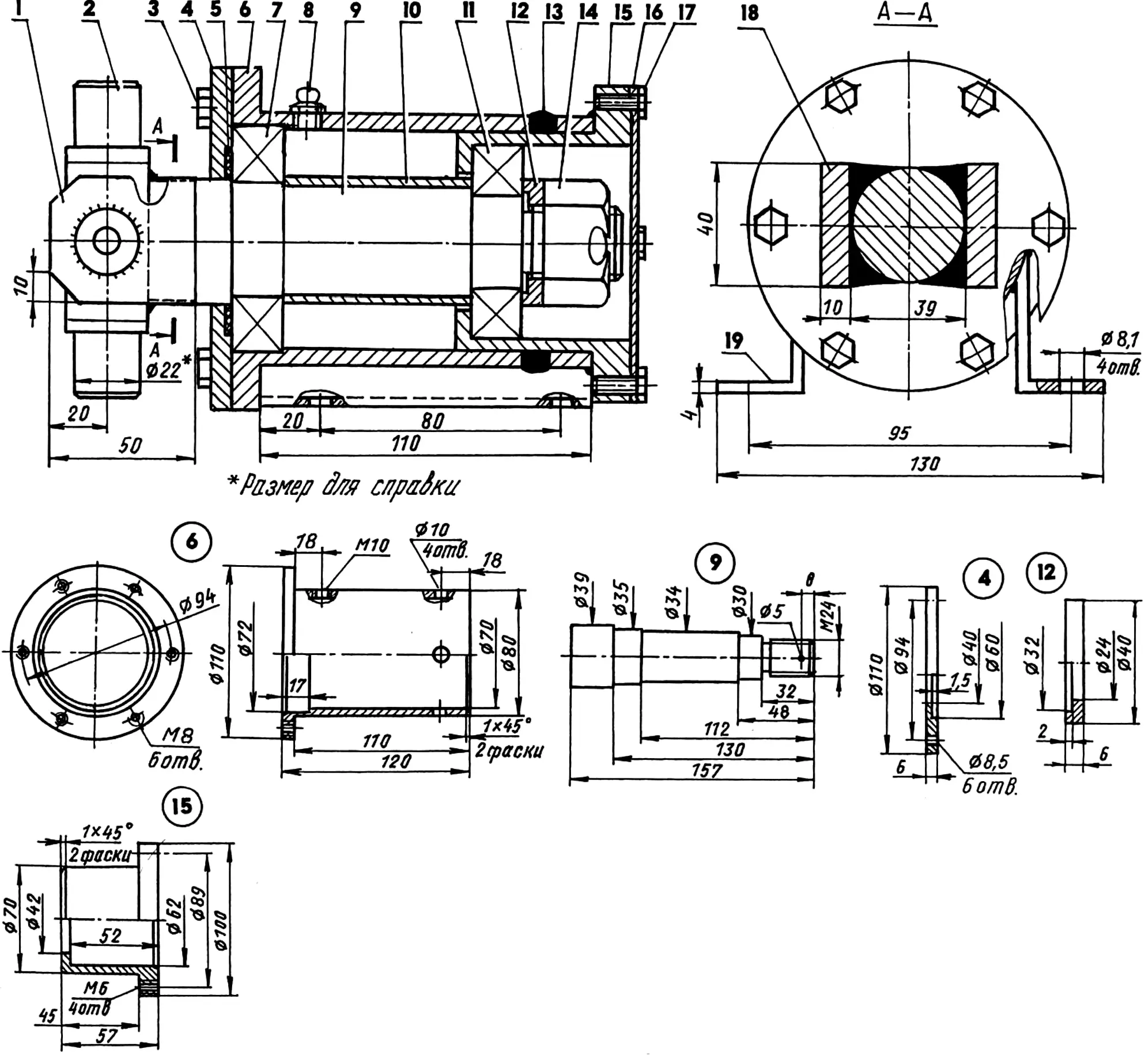
1,18 — cheeks (steel, strip s10); 2 — universal joint (from ZIL car driveshaft); 3 — M8 screw (6 pcs.); 4 — front cover; 5 — oil seal (rubber); 6 — housing; 7 — bearing 207; 8— grease fitting; 9 — shaft; 10 — spacer bushing (steel, tube 40×2.5); 11 — bearing 206; 12 — shaped washer; 13 — pop rivet (4 pcs.); 14 — M24 nut; 15 — insert; 16 — rear cover; 17 — M6 screw (4 pcs.); 19 — support (steel, strip s4, 2 pcs.)
The engine for the all-terrain vehicle was taken from a TMZ-5.403 “Muravei” cargo motor scooter together with its engine frame. If a factory engine frame is unavailable, a homemade equivalent is quite suitable. Its drawing is given for that case.
A driving sprocket (z = 14) is fitted on the engine output shaft. A primary chain with 12.7 mm pitch from it goes to the intermediate reducer with a driven sprocket (z = 42, from a “Voskhod” motorcycle) on the shaft. Play in this chain is taken up by turning the tension-bolt nut on the engine frame, which shifts the engine together with the engine frame forward.
There on the intermediate-reducer shaft is also a block of two driving sprockets (z = 11). Secondary chains with 15.875 mm pitch connect them to driven sprockets (z = 42, from an “IZH” motorcycle) mounted on the “Zhiguli” differential box instead of the planetary gear.
For tensioning the secondary chains there is a device with a block of two sprockets (z = 11) movable along a special platform on the transmission frame.
The differential box is sealed with a housing. A mixture of “TSIATIM” grease and transmission oil is poured into the box. The mixture is thinned to sour-cream consistency to prevent leakage through the gap between the half-shaft and the box.
In the differential box standard bearings were replaced with 207 bearings seated on the journals through thin-walled adapter bushings. Housings for the new bearings were made from flanges cut from the ends of the old “Zhiguli” rear-axle beam. Each is secured on the transmission-frame brackets with four M10 bolts.
1 — bumper (steel, angle 40x40x4); 2 — adapter (steel, sheet s3); 3 — primary-chain tension bracket (steel, sheet s5); 4 — beam (steel, channel 50x40x4); 5,6 — front and rear engine-frame mounting platforms (steel, sheet s5, 4 pcs.); 7,12 — support posts (steel, tube 22×3); 8 — intermediate-reducer bracket (steel, sheet s4, 2 pcs.); 9 — differential bracket (steel, sheet s4, 2 pcs.); 10,17 — side members (steel, tube 25x25x2); 11 — spatial steering-mechanism bracket (from “Zaporozhets”); 13 — shelf under intermediate-reducer bracket (steel, sheet s3, 2 pcs.); 14 — shelf under differential mounting bracket (steel, sheet s3, 2 pcs.); 15 — master brake-cylinder mounting bracket (steel, sheet s8); 16 — transmission-frame mounting plate to cabin front wall (steel, sheet s3); 18,20 — cross members (steel, tube 25x25x2); 19 — M8 bolt (4 pcs.); 21 — secondary-chain tension-device mounting platform (steel, sheet s6)
Half-shafts assembled with wheel discs and brake drums are also “Zhiguli” parts. The discs were adapted for pneumatics consisting of rubber tubes nested one inside another, sized 1065x457x420 mm (from a GAZ-66 vehicle or tractor trailer).
All four wheel suspensions are rigid, tubular.
Front suspensions are structures consisting of horizontal half-shaft housings, each reinforced with three braces.
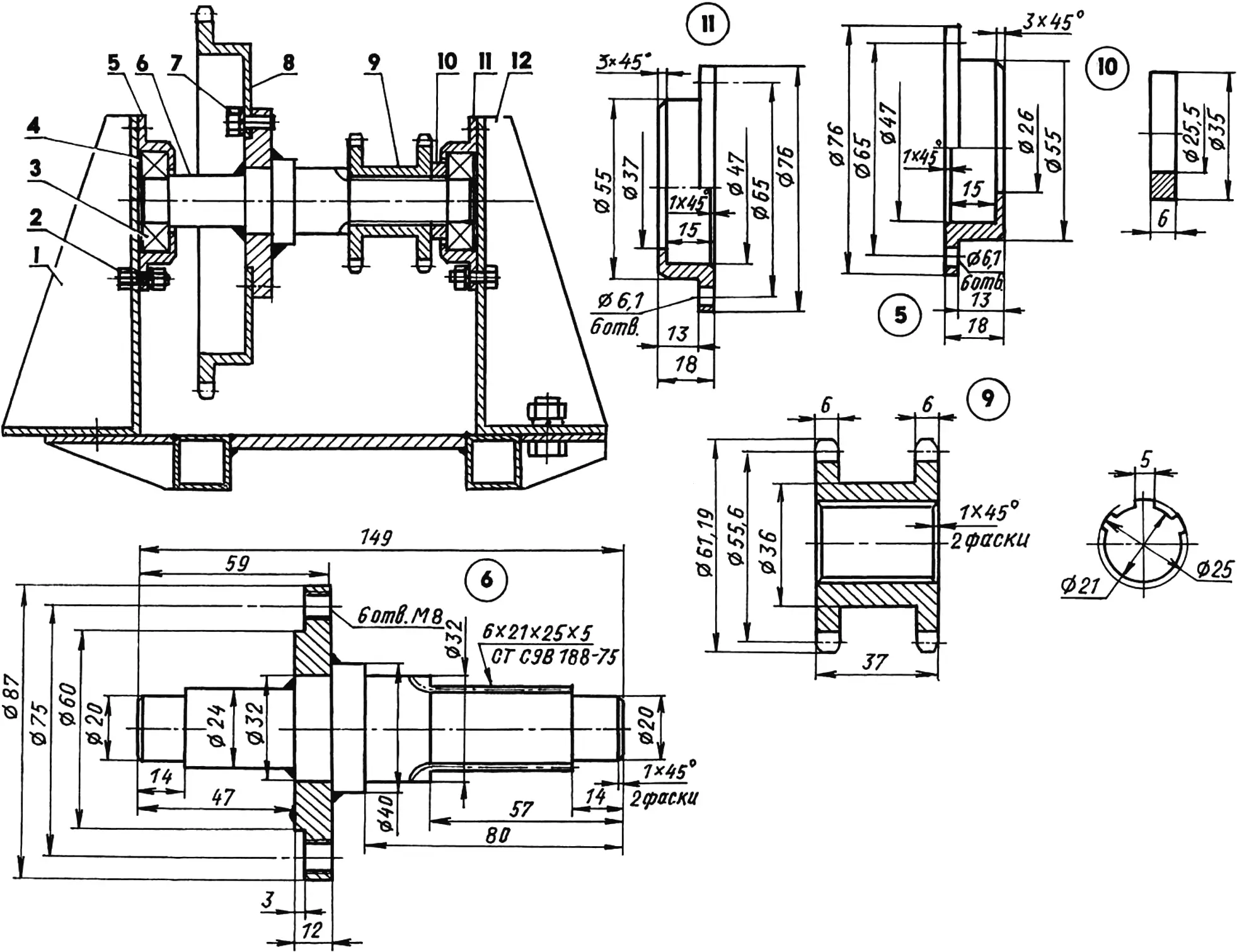
1,12 — transmission-frame brackets; 2 — M6 bolt (12 pcs.); 3 — bearing 204 (2 pcs.); 4 — spacer washer (steel, sheet s1, 2 pcs.); 5,11 — bearing housings; 6 — shaft with welded flange; 7 — M8 screw (6 pcs.); 8 — driven sprocket (z = 42, t = 12.7); 9 — sprocket block (z = 11, t = 15.875); 10 — spacer bushing
The housings are homemade, made from 50×3 mm steel tube. Flat flanges for attachment to the tractor sides are welded to their inner ends, and flanges (also bearing housings) cut from a “Zhiguli” rear-axle beam are welded to the outer ends. Braces made of 22×3 mm tube are welded to these housings.
The housings are attached to the tractor shell with flat flanges using 2 mm rubber-sheet gaskets; the braces are attached with angle brackets, without gaskets.
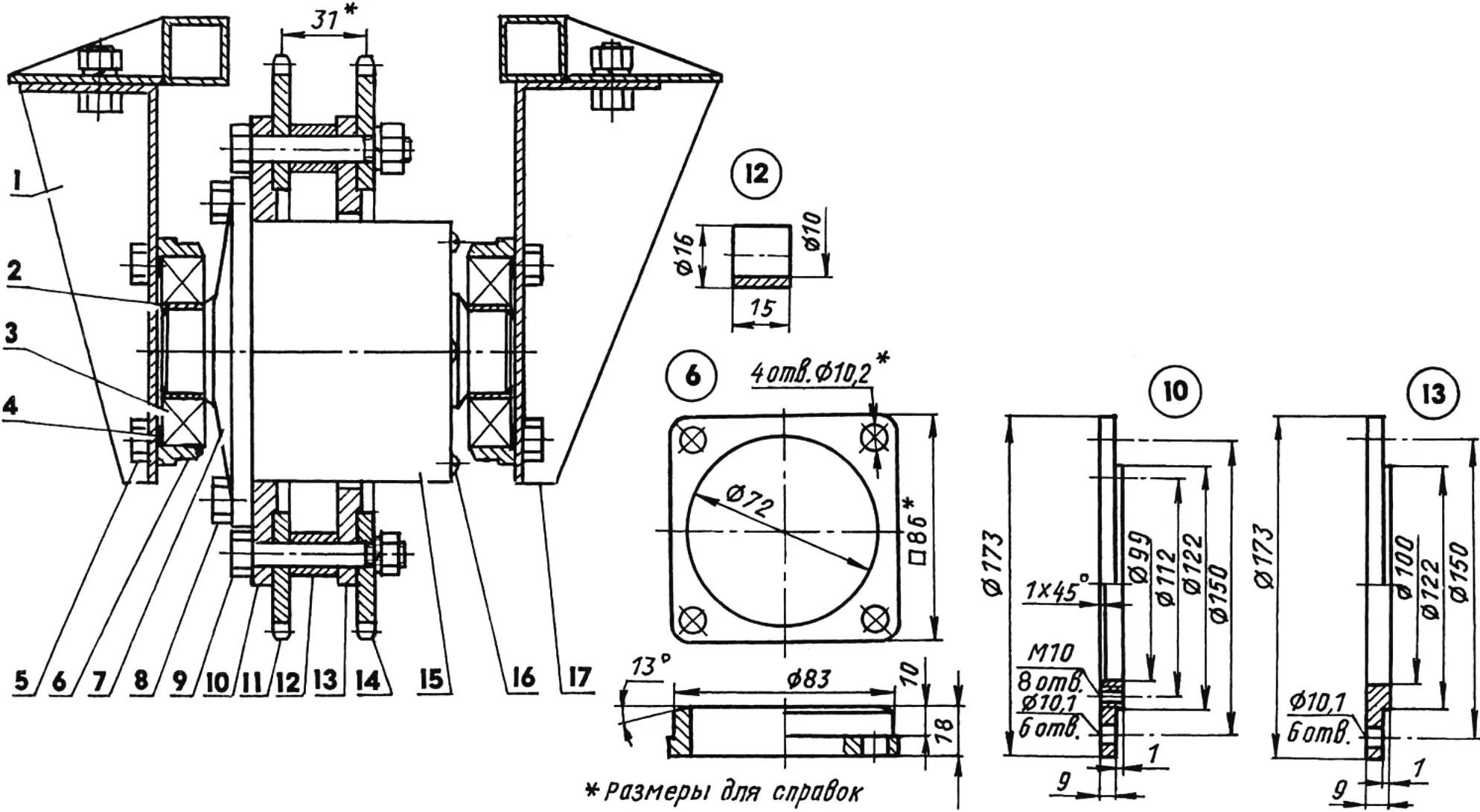
1,17 — transmission-frame brackets; 2 — adapter bushing (steel, 2 pcs.); 3 — bearing 207 (2 pcs.); 4 — spacer washer (steel, sheet s1, 2 pcs.); 5 — M10 bearing-housing mounting bolt (8 pcs.); 6 — bearing housing (2 pcs.); 7 — differential box (from “Zhiguli” car); 8 — M10 left-ring mounting screw (8 pcs.); 9 — M10 tie bolt (6 pcs.); 10,13 — rings; 11,14 — sprockets (z = 42, t = 15.875; from “IZH” motorcycle); 12 — spacer bushing (6 pcs.); 15 — differential housing; 16 — M5 housing mounting screw (4 pcs.)
The vehicle is equipped with “Zhiguli” hydraulic brakes with drive to the front wheels only.
Rear-wheel suspensions have no housings and each consists of three braces converging on welded flat flanges. Standard bolts secure bearing housings with hubs, driven forks, and brake drums from “Zaporozhets” rear wheels into the central holes of these flanges.
Rear-suspension braces are attached to the body shell with their angle brackets.
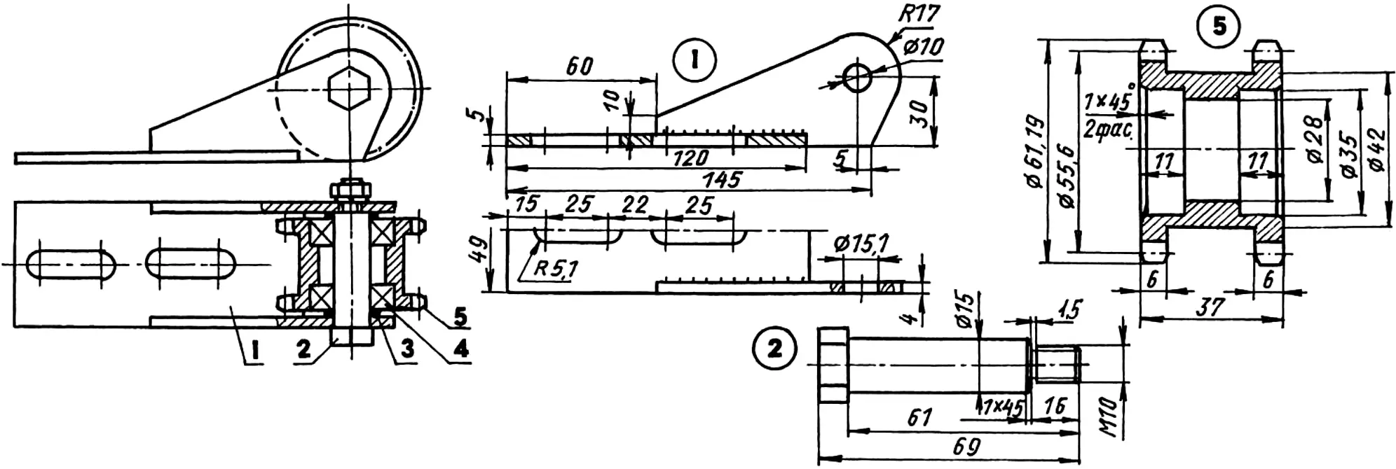
1 — bracket; 2 — special M10 bolt; 3 — washer (s2, 2 pcs); 4 — bearing 202 (2 pcs); 5 — sprocket block (z = 11, t = 15.875)
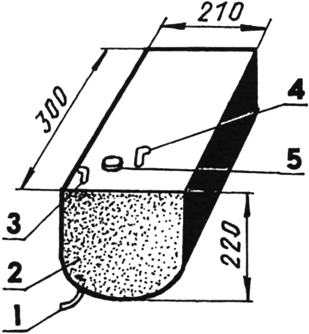
Rear-wheel pneumatics consist of rubber tubes nested one inside another, sized 710×300 mm (the outer tube is cut along the torus minor diameter). The inner tube valve is brought out through a 30×10 mm hole cut in the split-disc drum in place.
On the discs the pneumatics are held from rotation by six tread bands each. The bands are attached to the disc edges with double hooks of spring steel wire. Holes for the hooks are drilled in place.
Rear-wheel discs are homemade. Each consists of a cylindrical drum welded from sheet steel, with “Zaporozhets” wheel-disc halves attached to its ends: one by welding, the other with six M8 bolts.
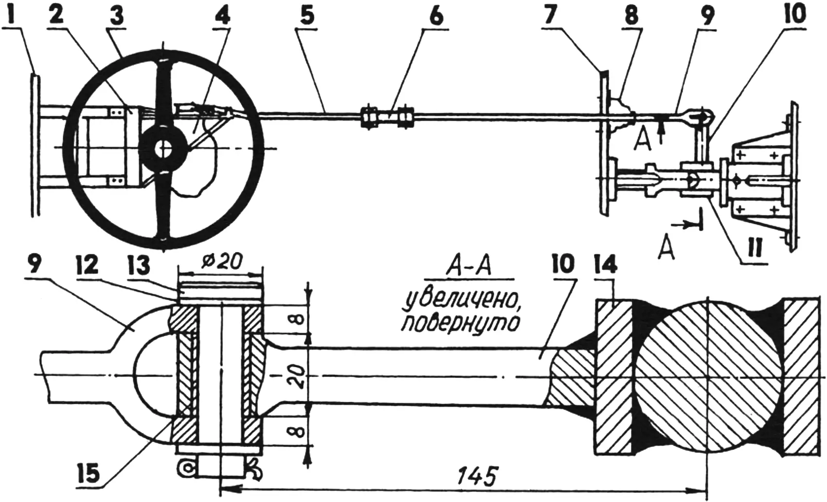
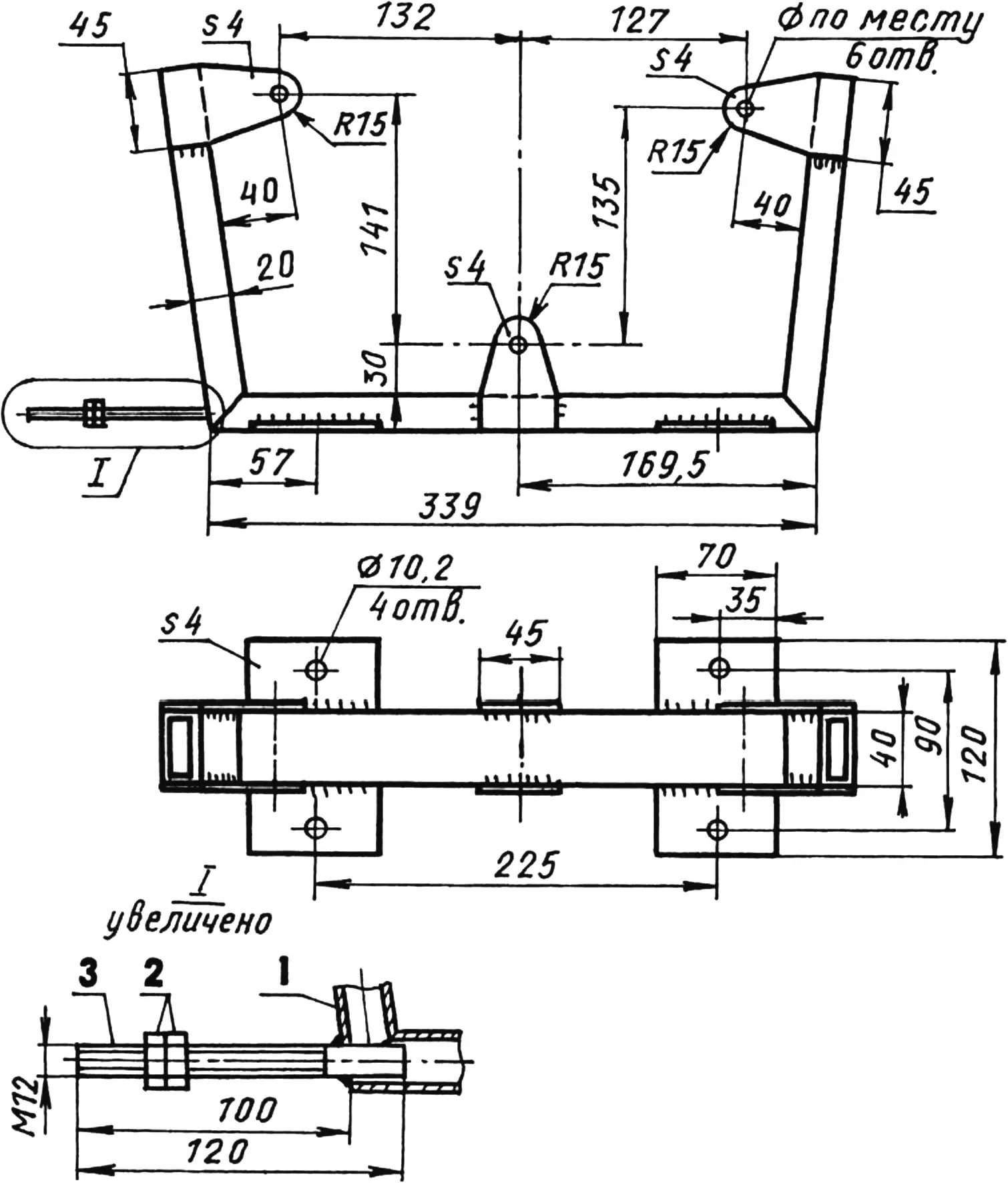
1,7 — cabin front and rear walls; 2 — spatial transmission-frame bracket; 3,4 — steering wheel and steering mechanism (from “Zaporozhets”); 5 — rod; 6 — adjusting coupling; 8 — rubber boot; 9 — fork; 10 — pitman arm (from bicycle pedal lever); 11,14 — hinge-unit cheeks; 12 — washer (s2, 2 pcs.); 13 — pin Ø12; 15 — bushing (bronze, tube 14×1)
Pedals and the steering mechanism from a “Zaporozhets” are used to control the vehicle. All these controls are mounted on a special spatial bracket in the cabin. The bracket is welded from square steel tube and attached to the transmission-frame beams passed through the front panel into the cabin.
The engine is started with a dynostarter powered by the battery, although the kickstarter can also be used. To avoid starting problems even at —15 °C, a special flap is provided in the pipe behind the air filter to limit air access to the carburetor during start. Thus the fuel mixture is enriched and the engine starts very easily. It then continues running on magneto ignition.
1 — welded frame (steel, tube 40x20x3, sheet s4); 2 — M12 nut and locknut; 3 — M12 tension bolt
The 13 L fuel tank is homemade, made of galvanized steel sheet. It is in the engine compartment on the port side (to its starboard is the battery) and is strapped to the cabin front panel with two metal band straps.
1 — feed fitting (fuel supply to pump); 2 — tank body (galvanized steel sheet); 3 — overflow fitting (fuel return to tank); 4 — drain tube; 5 — filler-cap cover
Since the tank is located quite low relative to the carburetor, a pump from an outboard motor is used for uninterrupted gasoline supply. To prevent carburetor flooding during abnormal pressure rise, fuel is returned from the float chamber to the tank. A calibrated overflow jet with a 1 mm hole is inserted into the return fitting.
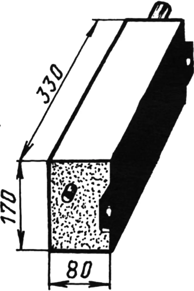
The exhaust muffler resonator is also homemade. It is made of stainless steel as a rectangular box measuring 330x170x80 mm and mounted on the tractor’s starboard side outside, between the shell and the wheel.
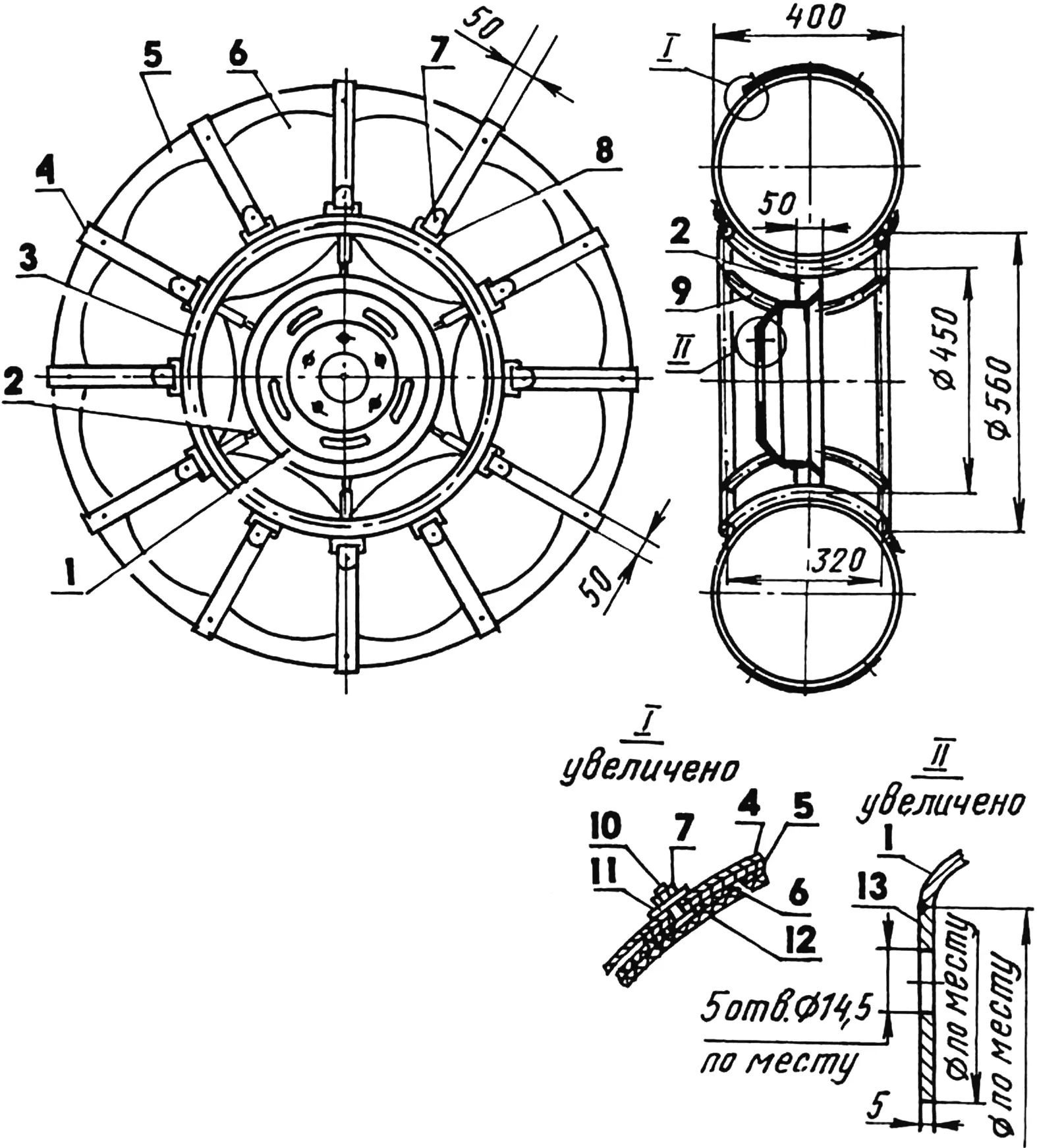
1 — disc (from VAZ-2101, trimmed); 2 — spoke (steel, strip 50×5, 6 pcs); 3 — rim (tube 16×3, 2 pcs); 4 — tread band (belt 50×5, 12 pcs); 5 — tread (conveyor belt 270×5); 6,12 — outer and inner pneumatic tubes (1065x457x420); 7 — M8 nut (48 pcs); 8 — loop (rod Ø8, 24 pcs); 9 — cradle (tube 22×3, 6 pcs); 10— M8 bolt (48 pcs); 11 — washer (48 pcs); 13 — adapter (steel, sheet s5)
The vehicle has electrical equipment including one headlight, turn signals, marker lights, and a stop lamp.
However, life does not stand still. You quickly get used to good things and start wanting something new again. My “little” all-terrain vehicle is no longer a novelty. And going fishing alone has become rather dull. So the time has come when I began thinking about a multi-seat design.
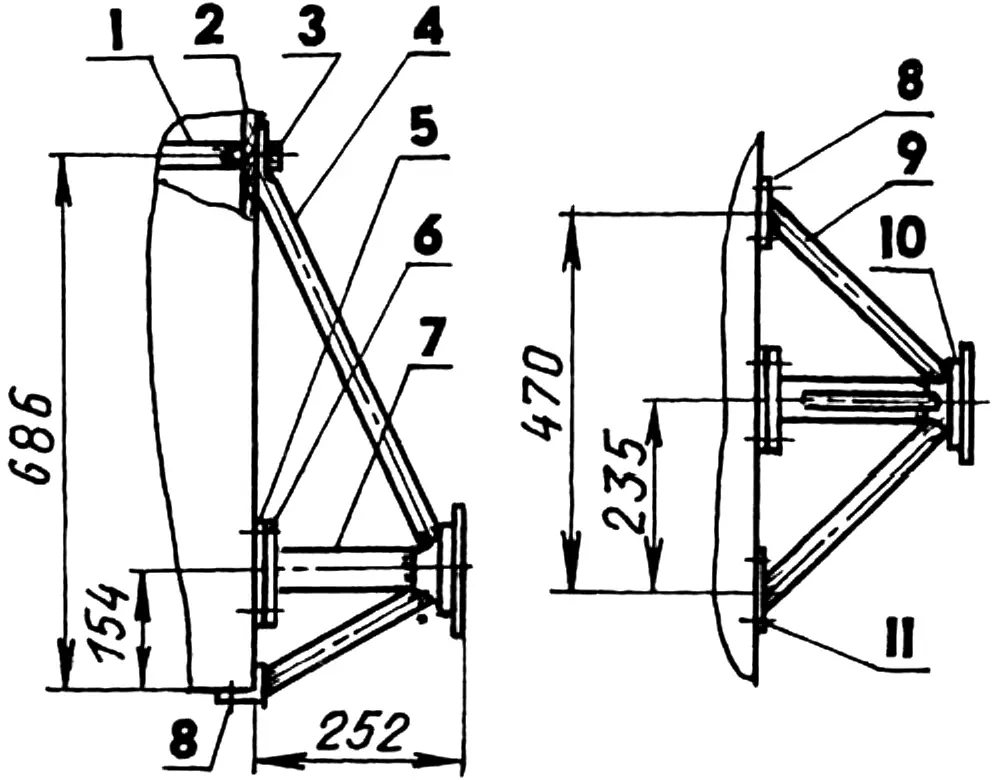
1 — under-hood brace (steel, tube 25×2, L726) with M12 nuts welded on the ends; 2 — tractor-shell side (plywood s12); 3 — M12 bolt; 4 — central brace (steel, tube 22×3); 5 — gasket (rubber s2); 6 — flange (steel, sheet s3, plate 130×130); 7 — half-shaft housing (steel, tube 50×3); 8 — bracket (steel, angle 40x40x2, L100, 2 pcs.); 9 — side brace (steel, tube 22×3, 2 pcs.); 10 — flange-bearing housing (from “Zhiguli” rear-axle beam); 11 — M8 bolt (12 pcs.)
I am now building a four-seat, already all-wheel-drive vehicle. Its design will use a 40 hp engine from a “Zaporozhets”, a transfer case with lock, independent suspension of all four “UAZ” wheels, and wheel reducers.
Approximate dimensions are 4000x1800x1600 mm. Maximum speed up to 70 km/h.
With the rear seats removed, two people can comfortably sleep in the cabin overnight.
“Modelist-Konstruktor” No. 12’2003, B. RYZHOV
Recommend to read
 TREAT THE BIKE
Boys — people are desperate: the bike chase so that injuries are not only them, but also technology: the wheel rim is bent, the frame or the fork. If this happens, do not have to seek...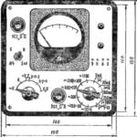 FIVE INSTRUMENTS IN ONE
Perhaps the most difficult stage in the process of creating radiokonstruktor — setting. But if you have even the simplest instrumentation, to establish any electronic device will be much...
