Choosing the size of the ship, we proceeded first of all from the crew of. Under the terms of the safety of navigation on Board must be at least two people. Since the increase in teams would lead to a significant increase in size, it was decided to build a catamaran double. Its payload capacity was 240 kg, the total displacement is 300 lbs. Taking three times the reserve buoyancy, we received estimated net floats 900 L. Rigid frame for connecting the floats collected from the lungs of dural pipes Ø 40, 50, 60 and 70 mm. Application of telescopic pipes has allowed to reduce the dimensions of the main box metal catamaran to the dimensions of the 2200X150X150 mm. mounts were constructed using a minimum number of fasteners is facilitated and sped up the Assembly.
The design feature of a catamaran — the original frames that allows you to change the profile of the waterline of the float. At the ends of the frames are set to mount the bayonet, because of them easily detachable longitudinal stringer-rope.
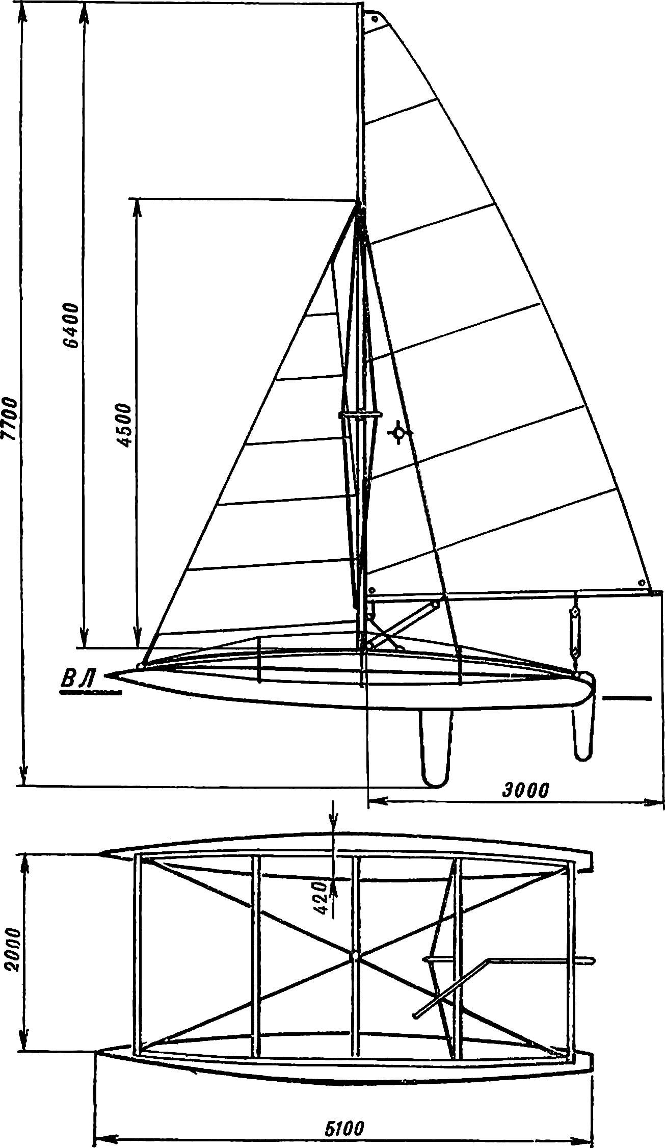
Fig. 2. The General structure of a catamaran:
1 — float, 2 — longitudinal beam of the frame (stringer), 3 — cross-beam frame, 4 — jib, 5 — mast, 6 — the gaff rig, 7 cave, 8 — geek 9 — tiller, 10 — rudder 11 — tent, 12 — forward and aft cross beam, 13 — podmazova cross beam 14 is a support fitting 15, and the bow fitting, 16 — spacer 17 — steps, 18 — frames.
On the “Impulse” delivered one centerboard, mounted on the beam using a special hinge providing two degrees of freedom. The vertical position of the centerboard is fixed by two pairs of rope stretch marks. This mount eliminates the extra beam and therefore reduces the weight. In addition, it makes it easy to take the centerboard ago when moving in shallow water or when the courses of the wind (when the centerboard only slows the ship), and also gives the opportunity to slightly shift the center of lateral resistance (TSBS).
Is the design of the catamaran and other original solutions. Perhaps the most critical element of the ship — it floats. They are manufactured from rubberized fabric of the type BZW suitable and “Serebryanka” or so-called “reclamation” fabric. To provide sufficient strength, the material is duplicated. To do this we recommend the following. After both pieces of fabric coated with two layers of rubber cement and dried, one of them is applied a thin PVC film, 50-100 mm wider than the strip of fabric. Then a fabric tape is wound on the outside light pipe with a diameter of 50-100 mm. of the Resulting roll is placed on the edge of the second pre-prepared piece of material and the overlapping edges is unwound by about 500 mm, then the roll is rolled again so that he rolled over the fabric without the raids and folds. Now, with tucked the tape in, I gently separated her, simultaneously rolling and smoothing out the second piece of fabric. If the edges of the canvases begin to diverge, they gradually combine. After this operation the material with the effort rolled the bottle across the surface.
The float is cutting with single longitudinal seam (Fig. 3). To glue it starting from the middle. To ensure sealing at the junction of the inside and outside glued a strip of fabric with a width of 30 mm; the joints must have a width of 25 mm.
Fig. 3. Cutting of float.
Inflate the float through the nasal fitting large diameter — the length of rubber hose with inner Ø 24 mm, densely inserted in a thin-walled dural tube (Fig. 4A). Rubber hose is sealed in a machined PCB tube filled with foam. Accessory fitting (Fig. 4B) in the middle of the float is used for paging afloat.
Fig. 4. Fittings:
A — bow: 1 — the shell of the float, 2 — adaptor (rubber hose), 3 — insertion (tube made of aluminum 25X1 mm), 4 — foam filling, 5 — tube from the PCB; B — auxiliary: 1 — cover float, 2 — washer 3 — nut, 4 — hull fitting.
Sealing the stern of the float (Fig. 5) allows you to quickly open it, turn inside out and repair. It is this: the aft part of the float is folded in four, is bent around the rubber cord Ø 3 to 5 mm and is placed inside the slit along the dural tube. To folded material easily and without damage slipped into the slit of the tube, its round brass foil. The tube is clamped by means of through bolts M4.
Fig. 5. Scheme of seal poop float:
1 — conquest (pipe made of aluminum, Ø 30X1,5 mm), 2 — bolt М4Х35, 3 — strip (copper foil), 4 — shell of a float, a 5 — rubber cord, 6 — nut.
Lugs under the frame glued to the floats after they are inflated. (The last operation in the home, it is advisable to perform with your cleaner.) The lugs themselves are formed of double-folded and glued with a fabric size of 80Х25 mm. In the places of gluing the shell is enhanced by a rectangular patch with size of 40X60 mm.
The frame of the catamaran is a set of duralumin tubes. Each stringer will go for the two pipe size 2200X40X2,5 mm, and the dock fits over the sleeve and the pipe section 180X44X2 mm, which is fixed by two M4 screws with countersunk heads. The aft stringer is free to enter into the sleeve during Assembly, and its tip are milled under the scope of the cross beams.
Four cross beam are made of pipe Ø 50X1,5 mm, and one podmazova — pipe 70X2 mm. at the ends they are milled so that covers a little more than half of the diameter of the beam-stringer. At a distance of 55 mm from the ends of the middle cross beams in the same plane diametrically drilled through-hole Ø 26.5 mm, in which are inserted the rack frames (see figure 6). The frame is a section of pipe, curved according to the diameter of the float and fastened with the upright triangular plate gusset plate made of aluminum with a thickness of 1 mm with five rivets. On the counter is put on first thrust ring with two threaded M4 holes for fixing the height of the frame relative to the frame, and then simultaneously cross beam and the clamp mounted thereon the stud-stretching M8. This pin is inserted through the diametrical hole of the stringer and is tightened by a nut-lamb. At the ends of the frame are grooves — locks the bayonet under the stringer-wires, and the top of the strut a slot width of 4 mm for stacking the carrier rail of the float.
Fig. 6. A typical coupling Assembly bulkhead, stringer and cross beam:
1 — stud-stretch, 2 — nut-lamb 3 — stringer 4 — cross-beam, 5 — clamp, 6 — frame, 7 — vant-potens, 8 — pin, 9 — plate 10 — lanyard, 11 — thrust washer, 12 — plate-gusset plate, 13 — frame, 14 — groove lock bayonet type.
In the extremities of the vessel are the same type of the attachment of the stringer and the cross beam (Fig. 7). The principle of their device is similar to that just discussed, only added fingers to fasten the stringer-wires and l rail and diagonal cables.
Fig. 7. The model of the bow (stern) the coupling of the stringer and the cross beam:
1 — stud-stretch, 2 — cross beam, 3 — stringer, 4 — pin for mounting cables rails l, 5 — cable-guy the forestay, 6 — finger for fastening the stringer-rope, 7 — bushing Ø 14X2, 8 — yoke, 9 — nut-lamb.
To Central beam is not buckled under the pressure of the mast, made a special strut that supports the beam with two diagonal ropes-stretch marks. Its design is shown in figure 8. The spacer consists of ten parts, the main of which is the dural tube size 240X20X1 mm. In the upper part of the pressed on sleeve with pin — it fitted with a nylon washer, providing the sliding in the stand rotation. On the lower portion of the tube pressed onto the threaded bushing M18. It screwed hollow screw M18, machined out of aluminum and have M8 threaded hole for the mounting bolt. The spacer fits over the stainless sleeve attached unit of the PCB; it can freely rotate around the girth, but is restricted from longitudinal displacement on the one hand the end face of the threaded sleeve and on the other thrust washer. Through the unit passes synthetic rope (the centerboard-tal), with the help of a centerboard mounted in a vertical position.
Fig. 8. Strut:
1 — pin, 2 — nylon washer 3 — sleeve, 4 — tube, 5 — pin (insulation tape, 3 layer), 6 — snap ring Ø 30X20,1X5, 7 — screw M18, 8 — hub, 9 — textolite unit Ø 40X30X15, 10 — cheeks of the block, 11 — screw sleeve 12 is notched washer, a 13 — diagonal cable, 14 — puck. 15 — bolt M8.
The deck replaces the awning of a synthetic fabric size 2100X2100 mm, pull on both sides of the Central transverse beam.
The mast of a catamaran consists of three sections with a length of 2200 mm — dural pipes Ø 70X2 mm. Sections are joined by molded inside the bushing and to prevent rotation relative to each other, at the ends of the mating parts made ledges, ensuring accurate docking tube, respectively, sections of the face-grooves (Fig. 9). Lik-groove made of U-shaped aluminium channel of size 20X20 mm, used for fixing glass panes. It has an internal ledge on both sides, eliminating the biting lik-rope. The technology of manufacturing the face-groove clear from figure 10.
Fig. 9. The junction of the sections of the mast:
1 — section mast 2 — M4 screws with countersunk head, 3 — face-and-groove 4 — M3 screw with countersunk head, 5 — Bush.
Fig. 10. The scheme of manufacturing the face-groove:
1 — aluminum channel, 2 — pad of the PCB, 3 — wire-mandrel 4 and the tube — mandrel; And — direction of deformation.
The design of the bottom end of the mast (spur) is shown in figure 11. It includes dural sleeve, which is tightly pressed into the end of mast tube and fixed by four screws M4. In the sleeve screwed ball support pin Ø 30 mm. With the installation of masts finger rests on the bearing (steps) from kaprolon, mounted on the Central transverse beam with six M4 screws.
Fig. 11. Knots masts:
1 — mast, 2 — swivel clamp, 3 — prong made of aluminum, 4 — bushing (steel tube Ø 10X1,5 mm), 5 — hinge, 6 — hull 7 — a bolt of M6 with nut, 8 — loop for guy geek, 9 — M4 screw (4 PCs), 10 — bushing, 11 — the spherical hinge, 12 — steps, 13 — M4 screws (6 PCs), 14 — podmazova cross beam, 15 — M4 screw (6 PCs.).
At a distance of 500 mm from the spur to the mast is attached to the swivel clamp of stainless steel with a thickness of 1.5 mm covering the mast and held with the pinch bolt M6. This design allows you to set the swivel at the desired height. Pin swivel made of aluminum and is pressed into the stainless steel tube Ø 10X1,5 mm (see figure 11).
On the top of the mast is fitted with two diametrically small block is passed through them steel wire rope (main halyard).
To increase the rigidity of the mast is used the gaff rig with three removename (Fig. 12). Its main element clamp Ø 70 mm, made of spring sheet steel, 2 mm thick, to which are welded two hinges and stud M8. In addition, the gaff rig consists of three racks with two connecting levers. The Central strut screws onto is welded to the clamp pin; all other connections of the levers and racks — swivel. On the ends of the side pillars are cut-outs for cables ambulant. All of these details dural. In General, the design crispity is not directly bolted connections with the mast, and is fixed by moving the Central racks, crimping the clamp. This gives the opportunity to provide a different profile of the deflection of the mast required for the correct settings the main sail (mainsail).
Fig. 12. The gaff rig:
1 — plate with a cutout under ambulant, 2 — connecting arm (2 PCs.), 3 — pillar, 4 — yoke, 5 — loop (2-piece), 6 — cotter pin Ø 2 mm, 7 — pin M8, 8 — side rack (2 PCs.).
Ambulanti made of galvanized steel wire ropes Ø 2 mm. At their ends are fire, United rigging brackets. When you install ambulant lifting brackets are attached to the mast with the help of special hooks. The deflection of the mast is adjusted by changing the length ambulant, which is possible thanks to the installed bottom screw lanyards.
As the guys and the forestay used galvanized steel cable Ø 3 mm. Sealing of the cable was carried out by using annealed copper tube length 20 mm — planted it on the cable and bent the hammer in the holster.
Gik collected from dural pipes with a length of 2200 and 900 mm Long pipe has a Ø 60X1 mm, and short 63X1,5 mm. At the junction of the two sections are bolted.
The centerboard (Fig. 13) made of a set of wooden slats cross-section of 20X25 mm, glued together and machined along the profile in accordance with Fig. Wooden set of centerboard top is covered with a single layer of fiberglass. Installing using the hinge device (Fig. 14), consisting of a clamp pin with pin and hinge. The clamp has a bend from strips of stainless steel sheet 2 mm in thickness. Hinge is formed by two welded perpendicular to cut stainless steel tubing. Of the same metal — pin device, the point of entry into the body of the centerboard is reinforced fittings made of aluminum. The clamp covers svetovou the beam, and the vertical position is provided by two pairs of cables connected to the cross beams using lanyards. Using the last back stretch out vtupuyu and front are set relatively freely, so that when movement of the incoming flow has picked up the slack of one of the cables and thereby created the angle of attack, compensating the drift of a catamaran.
Fig. 13. The centerboard.
Fig. 14. The hinge device of the centerboard:
1 — clamp 2 — sea bolt, 3 — transverse hinge sleeve, 4 — weld, 5 — longitudinal hinge sleeve, 6 — pin.
Steering gear (Fig. 15) consists of a steering box, pen, and tiller. The rudder is cut from plywood with a thickness of 20 mm and has a profile similar to the profile of the centerboard (NACA 0006). Outside it is glued by one layer of fiberglass on the basis of epoxy glue. Rumple, of duralumin tubes with a diameter of 22 mm, a tiller extension is a thin — walled tube of the same material Ø 20 and length 1000 mm.
Fig. 15. Steering gear:
1 — rudder, 2 — panel, 3 — fork, 4 — transverse beam of the frame, 5 — tiller 6 — outlet, 7 — box, 8 — Sorlin.
Fig. 16. Cutting sails catamaran:
A — staysail, B — grotto.
Cutting of the sails of the catamaran shown in figure 16. On the technology of their manufacture, and also about the transaction standing and running rigging can be found in the books of D. A. Kurbatov “15 designs for Amateur-built” (Leningrad: “Shipbuilding”, 1985), and V. M. Borisov “Sail boat” (Leningrad: “Shipbuilding”, 1985).
Disassembled the catamaran fits into three packages. One of them is the bag, length 2300 mm — fit all pipes, frame and mast. This also removed the battens, sails, centerboard and rudder. The second package is intended for floats and frames, and the third for sails.
The Assembly of the catamaran begins with the installation of the frame, and then stretched the awning, unfold the floats and their lugs pass through the stringer-wires. Then the frame is inverted the frames up, and the floats are placed along the stringers to the frames. Stringer-ropes attached to the extremities of the longitudinal beams in the middle part of the plant in the bayonet grooves, and only then inflate the floats. Set podmazova strut, centerboard, steering system and finally the mast. To perform the latter operation catamaran showered on one float, and the spherical bearing of the mast is inserted into the steps podmazova beams. Completes Assembly of the vessel installation of the rigging and setting sails. In General, the disassembly of the catamaran takes one hour, and the Assembly and a half.
V. USPENSKY, M. USPENSKY, N. KUZNETSOV
Recommend to read INVENTIVE BED Creative search is possible in all areas, and agriculture is no exception. For example, at the individual plot of each can experiment as much as you want at your pleasure. So I went to... FOR COMBAT AND AEROBATICS Universal control line model aircraft. The design "Teardrop" models for air combat — have occurred in several stages. In fact, immediately, in one step to create obedient to the pilot... 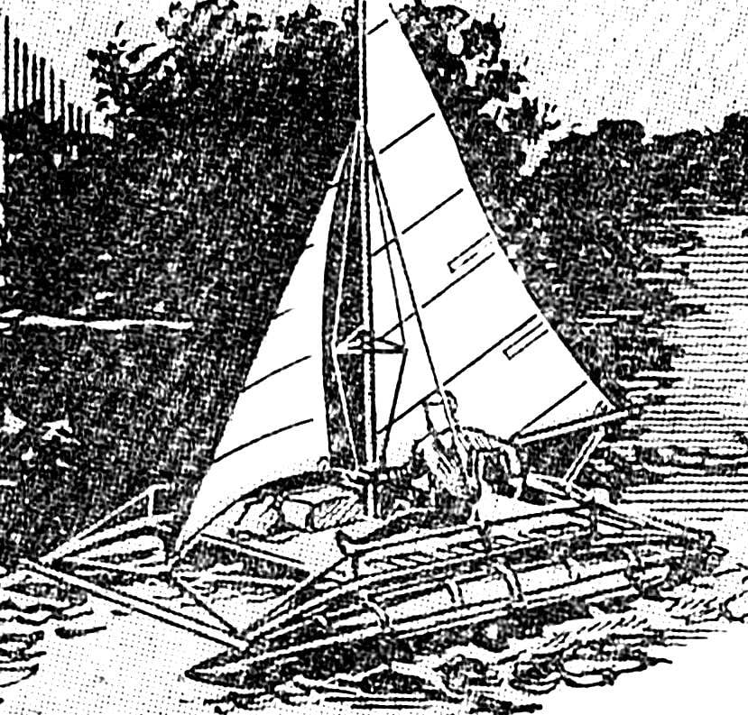
 Filled with wind-taut sail… This age-old symbol of romance will not leave anyone indifferent. And there is nothing surprising in the fact that the number of sailing enthusiasts every year increases. Today they are much more than you can take the yacht clubs, so work on creating Amateur sailing ships many have no qualified advice.