The frame (Fig. 3) make dry boards. To a vertical longitudinal edge (straightness where provided) at the time of Assembly and gluing of the spar are attached with screws, metal mounting plate at a distance of 400-500 mm from each other. The upper edge they need to rise above the horizontal plane at 22 — 22.5 mm.
Fig. 1. Assembly drawing of the blade:
1 – side member (plywood, is glued to the fiberglass); 2 – moulding (oak or ash); 3 – trailing edge (pine or lime); 4 – plank (pine or Linden); 5 – filler (foam); 6 – sheathing (2 layers of fiberglass s0,1); 7 – trimmer (duralumin grade D-16M s,2); 8 – rib (plywood s2 layer along)
Of the rotor blade (propeller) autogyro
Fig. 2. Rib
Fig. 3. Stapel
Fig. 4. Template (duralumin)
Fig. 5. Main template (steel)
Fig. 6. Trimmer
For each blade to be procured 17 strips of plywood, cut according to the drawing of the spar outer layer along with allowances for processing 2 – 4 mm on a side. Because of the size of sheet of plywood 1500 mm, in each layer of the inevitable bonding of the strips to us not less than 1:10, and the joints in one cloudline defend from joints in the other, following him at a distance of 100 mm. pieces of plywood are arranged so that the first joints of the lower and upper layers are spaced from the inboard end of the spar to 1500 mm, the second and penultimate layers – 1400 mm, etc., and the junction of the middle layer will be at a distance of 700 mm from the end of the butt of the blade. Accordingly, it will be distributed along longitudinal second and third joints zagotovlen bands.
In addition, you need to have 16 lanes of glass, of a thickness of 0.3 mm and a size 95×3120 mm each. Prior to this, they should be treated to remove the sizing.
Glue the blades in a dry room at a temperature 18 – 20°C.
FABRICATION OF THE SPAR
Before assembling the blanks, the slipway is lined with tracing paper, so that it does not pricipales of the workpiece. Then fit and aligned relative to the installation plates in the first layer of plywood. It is attached to the slipway thin and short nails (4-5 mm), which drive the butt and at the end of the blade, and one on each side of joints to prevent displacement of the segments of plywood in resin and fiberglass in the Assembly process. Because they remain in the layers, throw them randomly. Nails are driven in this order for fixing all subsequent layers. They must be made of soft enough metal not to damage the cutting edges of the tool used for further processing of the spar.
Layers plentifully moisten with roller or brush resin ED-5. Then successively applied to the veneer strip of fiberglass that is smooth with hand and wooden trowel until the surface does not seem resin. After that, the fabric, put a layer of plywood, which is first smeared with resin the side that will fall on the fiberglass. Typed thus the spar is covered with tracing paper, placed it on the rack sizes 3100x90x40 mm. Between the bar and bench clamps spaced 250 mm apart, along the entire length of the rods produces compression dialed pack until its thickness is equal at the upper edge of the installation plate. Excess resin should be removed before it hardens.
Harvesting of the spar is removed from the pile after 2-3 days and processed to a width of 70 mm into the profile part, 90 mm in the butt, and the length between the ends – 3100 mm. the Essential requirement which should be observed at this stage, the straightness of the surface of the spar, forming in the process of further profiling the front edge of the blade. The surface that will be glued to the ribs and the foam filling should also be fairly straightforward. Process it should be a plane and the knife of hard alloy or at least drachevye files. All four longitudinal workpiece surface of the spar must be mutually perpendicular.
PRELIMINARY PROFILING
The layout of the workpiece longitudinal produce. It is put on the slipway and on the end face, the front and rear planes cause the line spaced from the surface of the pile at a distance of 8 mm (~UN Mach). At the end end, in addition, draw with a template (Fig. 4) full profile of the blade 1:1 scale. Special precision in the manufacture of this auxiliary template is not required. On the outside of the template, put a line of chords and it is at the toe of the profile and the point at a distance of 65 mm from it drilled two holes with a diameter of 6 mm. Looking through the hole, combine the chord line of the template with the line drawn on the end face of the spar to put it on the line defining the boundary profiling. In order to avoid shifts of the template attached to the end of thin nails, which are drilled in it randomly placed according to their diameter.
The processing of the spars along the profile produce a simple plane (rough) and by a flat bastard file. In the longitudinal direction of the control line. When processing is finished, glue the ribs to the back surface of the spar. A precise installation is ensured by the fact that they are in the process of making put a line Expressway, which coincides with the line of chords, marked on the back plane of the workpiece longitudinal and a visual check of the straightness of their location relative to the auxiliary pattern. It again fastened for this purpose to the end end. Rib located at a distance of 250 mm from each other, and first exhibited at the beginning of the profile of the spar or at a distance of 650 mm from the end of the butt part.
ASSEMBLY AND HANDLING OF THE BLADE
After hardening of the resin between the ribs are pasted plates of foam corresponding to the profile of the rear part of the blade protruding ends of the ribs make the notches in the rail forming the rear edge. The latter is glued on
the resin to the ribs and the plates of foam.
Next, make a roughing the foam plates, the curvature of which is adapted to the curvature of the ribs, as well as remove the excess wood slats for the formation of the trailing edge, with some allowance for follow precise handling on the basic pattern (Fig. 5).
The basis pattern is produced first, with the allowance of 0.2 – 0.25 mm on the template specified values of SW and mm to get the profile smaller than the final size for pasting the fiberglass.
When machining the blades using the primary template for base is its lower surface. With this purpose verifies a radial line of the straightforwardness of its forming in the distance XH= 71,8 mm, where UN= 8,1 mm. Straightness can be considered sufficient in that case, if in the middle of a line of length 1 m has a gap of not more than 0.2 mm.
Then to the long sides well aligned dural plate size 500x226x6 mm are fixed guide rods of hard wood or of aluminum with a height of 8.1 mm. Distance between them for the upper half of the main template must be equal to the width of the blade, or 180 mm. the Latter are placed on the slipway on 3 to 4 plates with a thickness equal to the thickness of fixture plate, and press clamps. Thanks from-lichtovannaya plate can move between the staple and the lower surface of the blade along the entire length in the straight plane, which ensures the constancy of the thickness of the blade meets the surface to a specified profile.
The upper surface of the blade can be considered processed if the top half template is moved over its entire length without any gap around the profile and in places of contact of the template with the guide. The lower surface of the blades are checking fully assembled pattern, both halves of which are rigidly connected together. The upper and lower surface profiles using grachevich nail files with coarse and medium-cut, and hollows and bumps close up of the pattern with a putty of resin ED-5, mixed with wood flour, and again saw round pattern.
TAPING THE BLADES
The next operation is the pasting profile and butt portions of the blades fiberglass with a thickness of 0.1 mm in two layers on the resin ED-5. Each layer is a solid fiberglass tape, which is applied by its middle on the front edge of the blade. The main requirement that must be observed at the same time, the excess resin after the cloth is well saturated it should be carefully squeezed with a wooden float in the transverse direction from the front edge to the back of the fabric formed by air bubbles. None of the fabric should podvorachivaetsya or frown in order to avoid unnecessary bulges.
Paste over the blades, cleaned them with sandpaper, and the rear edge is adjusted to the thickness close to the final. Also check the profile of the sock member. While doing this using the main template, with certain allowances, as mentioned above, to ensure the quality of the profiling of the upper and lower surfaces.
Fig. 7. Square-pattern
Fig. 8. Construction of the profile (NACA 23012, b=180mm, sock ~ 2,85 mm)
Fig. 1. Device for balancing a rotor
Fig. 2. Strengthening the rotor
The basic pattern is adjusted to the desired size and use it to produce the final fit of the profile with the use of putty, with the basis again taken the lower surface of the blade, the circle line is checked again the straightforwardness of its forming in the distance XH= 71,8 mm from the tip. Convinced of its straightness, the blade is put on the slipway of the lower surface down on the padding with a height of 42 mm (this value is the rounded difference between the height of the lower half of the template and UN= 8.1 mm). One of the pads falls under the inboard portion of the blade, which at this point pressed to the bench clamp, the other along the blade at arbitrary distances from each other. After this, the upper surface of the blade is washed with acetone or solvent and is covered throughout its length with a thin layer of putty resin ED-5 and a tooth-powder of such density that it is easily distributed on the surface and did not flow down along the curvature of the profile (the consistency of thick cream). Fastened to the basic pattern slowly and evenly moving the blade along the beveled forward motion so that its edge all the time relied on a horizontal surface of the bench. Removing excess putty on the convex areas of the profile and leaving the desired quantity in the depressions, the pattern is so fine-tuning the profile. If you find that depression in some places were not filled, this operation is repeated after coating them with a thicker layer of putty. Excess plaster should occasionally be removed when it begins to droop from the front and back edges of the blade.
When you have to move the template straight and perpendicular to the longitudinal axis of the blade, moving it continuously to avoid surface irregularities of the blade. Allowing the filler to achieve full hardness and having smoothed it slightly with sandpaper, the operation of the final putty is repeated on the bottom surface, using the pads with a height of 37 mm.
FINISH BLADES
Making the blades, they are treated with sandpaper medium grain, paying special attention to the formation of the toe of the profile, washed with acetone or solvent and cover with soil No. 138, in addition to the attachment of the trimmer (Fig. 6). Then all the bumps close up nitroshpaklevok, making sure on profiled surfaces formed excessive thickening.
Final finishing work, which consists in the careful removal of waterproof emery paper of different grit of the excess putty, is carried out in accordance with the promotion of compactness of the pattern along the surfaces of the blade without excessive pitching and gap (not more than 0.1 mm).
After pasting of the blades fiberglass with a thickness of 0.1 mm and to cover them with soil on the inboard portion of the blades above and below on the resin ED-5 plate from glued oak or ash dimensions 400x90x6 mm, which ostrugivajutsja so that the blades acquired the installation angle enclosed between the chord and the horizontal plane and equal to 3°. It is checked using a simple template (Fig. 7) relative to the front surface of the butt, and controlling the parallelism of the formed surfaces of the top and bottom of the butt.
This completes the formation of the butt end of the blade, and he pasted over fiberglass 0.3 mm on the resin ED-5 to make the blade tightness. Ready the blade, except the butt, painted by nitroenamel and polished.
Advice on determining the actual position of the center of gravity of the blades, balancing and pairing with grommet, read the next issue.
ASSEMBLY AND ADJUSTMENT
In the previous issue, we described in detail the manufacturing process of the rotor blades of a gyroplane.
The next step is the balancing of the blades along the chord, assembling and balancing the rotor radius of the blade. The accuracy of the installation of the latter depends on the smooth operation of the rotor, otherwise it will arise increased unwanted vibrations. Therefore, the Assembly should be taken very seriously – do not rush, do not start work until you picked up all the necessary tools, fixtures and prepared workplace. When balancing and Assembly must constantly monitor their actions – it is better to measure seven times, than once to at least fall from a low height.
The process of balancing of the blades along the chord in this case is to determine the position of the center of gravity of the blade element.
The main purpose of requiring the balancing of the blade along the chord – to reduce the tendency to cause oscillations of the flutter type. Although the described machine the occurrence of these vibrations is unlikely, however, to remember them, and when adjusting you should make every effort to ensure that the CG of the blade was in the range of 20 – 24% of the chord from the nose profile. The blade profile NACA-23012 has a very small displacement of the center of pressure (CSD – the point of application of the aerodynamic forces acting on the blade in flight), which is in the same range that you and DH. This allows you to combine lines DH and CD, which virtually means the absence of a couple of forces which cause twisting of the rotor blades.
The proposed design of the blade ensures the desired position of the CG and CD, provided that manufacture them strictly according to the drawing. But even with the most careful selection of materials, the technology weighting of mismatch may occur in connection with and performs balancing operation.
To determine (with some acceptable error) the position of the CG is made of the blade, running the blade with the seam allowance on the ends 50 – 100 mm. After the final filing the allowance is cut off, the blade is ending, and the cut element is subjected to balancing.
Fig. 3. Assembly drawing of the rotor hub:
1 – stop angles (D16T); 2 – the axis of the rotor (30KHGSA); 3 – bottom plate sleeve (D16T, s6); 4 – the farm hub (D16T); 5 – axis of the main hinge (30KHGSA); 6 – bushing (bronze, tin); 7 – spacer Ø20 – 10, 5 – 0.2 (45 steel); 8 – bearing housing (D16T); 9 – hole for pin; 10 – cover housing bearing. (D16T); 11 – M18 castellated nut; 12 – washer Ø26 – 18, 5 – 2 (steel 20); 13 — the screw of fastening of a cover the M4; 14 – angular contact ball bearing; 15 – radial bearing No. 61204; 16 – a bolt of fastening of the blade (30KHGSA); 17 – plate blades (s3, 30KHGSA); 18 – washer has ø 14 – ø 10 – 1.5 (steel 20); 19 – self-locking nut M10; 20 – screw M8; 21 – bugey (Ø61, L = 200, D16T); 22 – pylon (tube Ø65×2, L=1375, lime)
Fig. 4. Farm sleeve
Fig. 5. The axis of the rotor (steel 30KHGSA)
Fig. 6. The bearing housing (ДТ6Т)
Fig. 7. The bolt (steel 30KHGSA)
Fig. 8. The limiting angles of deflection of the rotor (D16T)
For triangular, horizontally disposed prism of its lower surface, put the blade element (Fig. 1). His section plane along the chord must be strictly perpendicular to the edge of the prism. The movement of the blade element along the chord to achieve its equilibrium and measure the distance on the toe of the profile to the edge of the prism. This distance should be 20 – 24% of the chord length. If DH will go over that maximum limit for the nozzle profile in the terminal part of the blade will have to hang the anti-flatter cargo of such weight that the COG has shifted forward to the desired value.
The butt of the blade is reinforced overlays, which are steel plates 3 mm thick (Fig. 2). They are attached to the butt of the blade with rivets with a diameter of 8 mm and studs itati on any adhesive: BF-2, PU-2, ED-5 and ED-6. Before installing the pads in the butt of the blade grinded with coarse sandpaper, and the plate is treated by sand-blasting. The surfaces of the parts, i.e. the butt of the blade, lining the holes for the caps and the caps, carefully degreased and smeared with glue. Then clench the rivets and putting the rivets (4 pieces on each plate). After this operation, the blades are ready for the markings to install them on the bushing.
Rotor gyroplane (Fig. 3) consists of two blades, bushings, the axis of the screw with rolling bearings, bearing housings, horizontal hinge and limiter deviation angles of the axis of the rotor.
Sleeve consists of two parts: a U-shaped farms, and the lower plate (Fig. 4). The farm is desirable to make forgings. In the manufacture of it rental have to pay special attention to the direction of rolling was necessarily parallel to the longitudinal axis of the farm. The same naprawienie rental should be at the bottom of the plate, which is made of sheet duralumin brand D16T with a thickness of 6 mm.
Processing farm operation is conducted in the following order: first, the milled workpiece, leaving a seam allowance of 1.5 mm on the side, then the farm is subjected to heat treatment (hardening and aging), followed by final milling as per drawing (see Fig. 4). Then a scraper and sandpaper on the farm displays all the risks and applied transverse to the longitudinal bar.
The axis (Fig. 5) is attached to the pylon at two mutually perpendicular axes that allow it to deviate from the vertical at the required angles.
The main rotor hub
On the upper part of the axis is mounted in two bearings: the lower radial No. 61204, upper-angular contact No. 36204. The bearings are enclosed in a housing (Fig. 6), whose lower inner rim flight takes in entire load from the weight of the gyroplane. In the manufacture of the housing it is necessary to pay special attention to the processing of pairing the side with the cylindrical portion. Undercuts and risks in the interface is invalid. At the top of the bearing housing has two ears, which are pressed in bronze bushings. The holes in the bushings are processed by the scan after pressing. The axle bushing should pass through the axis of the body rotation is strictly perpendicular to it. Through the holes in the ears of the bearing housing and bushings that pressed into the cheeks of the farm, passes the bolt (Fig. 7), which is the horizontal hinge main rotor of the autogyro with respect to the axis of the blade which is making a flapping motion.
The angle of deflection of the axis and correspondingly change the position of the plane of rotation of the disk is limited by the plate fixed to the pylon (Fig. 8). This plate does not allow to deviate the rotor in excess of allowable angles, providing control of the autogyro in pitch and roll.
B. BARKOVSKY, J. RASUK
Recommend to read SILENT ROAR In the construction of cottages, garages in the farm economy often have to sift through loose building materials, soil or garden soil. It uses a special device — the so-called roar. His... THE DESCENDANTS OF A TORCH Have wood outstanding ability to split easily along the grain. This property we use, when Kohl firewood, split kindling. Wall panels (Fig.1), lamps, pencil holders, magazine racks... 
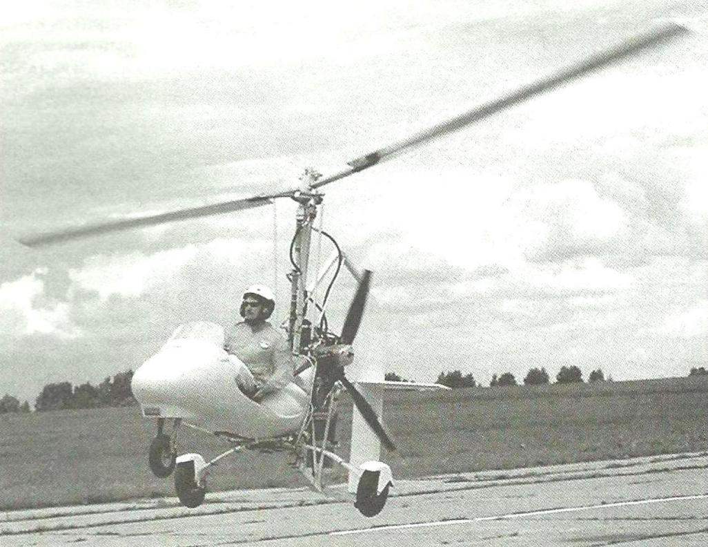 It is no exaggeration to say that the main airframe-the autogyro is the rotor. From the correctness of the profile, from weight, precision, alignment and strength depend on the performance of the gyro. However, non-motorized vehicle on tow behind the car rises only 20 – 30 m. But the flight at this altitude requires mandatory compliance with all previously stated conditions.