The “highlight” of the whole structure here — the windmill. First, it blade. A simple rotary yielding some of its archaic appearance, reminiscent of a medieval mill, which fought the infamous don Quixote, the windmill wins in the main: of power output to the load. Secondly, paired with the wind in this case is working… the sail at each of the three blades with variable area B* and self-restraint prescribed for the strong winds.
The fact that the blade node in the wing of the wind turbine consists of a rigid leading edge, of edges of the corresponding section and the “twist” that ensures optimal operation end, the middle parts and base, and a trailing edge, the tension of which provides steel cable. Sail the blades of synthetic varnish impregnated nylon. He stretched on the skeleton with fixing the clamping plate on the spacer-ground (see Fig.), and thanks to the rope is always taut. The fabric after impregnation of synthetic varnish has not lost its elasticity, and the blade is able to change shape in response to wind gusts. Automatically accepts and the best for each specific prevailing wind load, the pitch angle.
Well, what happened, will fly the hurricane. What then? Yes, nothing bad will happen. The cable that sets the tension of the trailing edge, so tense that at wind speeds exceeding the working range, the sail falls off as it becomes inactive because the mode of self-restraint, and — automatically.
Of other technical solutions, successfully fit into the design of the present wind-driven generator, not to mention the simplicity and reliability of performance of the slewing node, removal of power to the load, the use of a kinematic scheme is not angular gear, and the usual chain drives the successful placement of almost all kinematics in the capsule of the fairing. Has worked well in the case and the capsule itself.
Features of manufacturing of main components, as all the considered wind-driven generator, is a consequence of its originality.
Take, for example, the front edge of the blade node. In essence, this caisson design. It need body: side member with the corresponding interlocking elements. And they are not to be done without templates.
Templates will need six. Two forming ribs
blocks, three for jigs blade node (stocks) and one for the original steel edge. At their manufacturing requires the utmost precision and concentration, the purity of the markup.
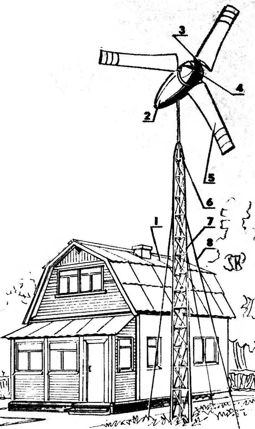
Fig. 1. The farmstead with auxiliary power supply (top):
1 – consumer of electricity (load), 2 a synchronous generator with transmission in the capsule of the fairing. 3 — spar blades (3 PCs.), 4 — Kok propeller, 5 — blade sailing (3 pieces), 6 of the slewing node, 7 — mast from the metal trusses, 8 – wire.
R and S. 2. Kinematics of wind-electrical installations:
1 — the sailing wind wheel three blade, 2 — ball bearing angular contact (2 PCs.), 3 — a pipe support of square section, 4 — shaft, 5 — radial ball bearing (2 PCs.), 6 — intermediate shaft 7 — transfer of power from the drive roller chain PR-19,05, 8 — cone, 9 — transfer of power from the drive roller chain PR-12,7, 10 — a synchronous generator with a power of 1200 W, 11 — stand-pipe interior, 12 — bearing, radial samonazvanie, 13 — stand-pipe outside, 14 — bearing, 15 — mast NC metal trusses.
Fig. 3. The manufacture of the blade:
1 — clamping strap (stripe a cross section of 3X25 mm, АЛ9-1), 2 — strut-basis (cut and riveted “epoxy” together with aluminium corners 25X25 mm to accommodate the desired configuration), 3 — sail (synthetic varnish impregnated nylon cloth weighing 113.4 g), 4 — large kosina (12-mm aluminum Bicycle), 5 — special configuration), 9 — rib”sandwich” (riveted and “epoxy” together blanks from 6 mm sheet АЛ9-1; 3 PCs.) 10 — a connecting bracket (20-mm cut aluminum area 25X25 mm, 6 PCs), 11 — small kosina (12-mm aluminum Bicycle), 12 — ending (cut riveted together and “epoxy” aluminium corners 25X 25 mm), 13 — liner lead (12-mm cut splashimage cylinder with an outer diameter of 12 mm and inner, 3 mm, 2 PCs.), 14 — the conduit (two sequentially composed of a segment of polyethylene tubing), 15 — cable straining.
R and S. 4. Stitching sails from billet, folded in half:
1 — band gain (75-mm width nylon) zakonopacheny part 2 — the seam allowance of 20-mm, 3 — processing of a cloth sail (nylon, folded in half), 4 — band amplification of the base (75-mm width nylon).
R and S. 5. Struts to hold the rope and tensioning the rear edge of the blade, their position relative to the ribs-“sandwiches” on the spar:
1 — edge”zaidun” (3 piece), 2 — the “nose” of resorce-ending, 3 — docking bracket (6 PCs.), 4 — shank strut-ending and (the same piece) spacer-mid, 5 — strut-mount.
Fig. 1. Templates for running blanks:
1 — molding bar (20 mm plywood), 2 — docking bracket, 3 — contour of the wood block, and the second layer edges-the”sandwich”, 4 — the first layer of the edge”sandwich”.
Fig. 7. Stapel:
1 — basis, 2 — bar, 3 — front-locking blade spar (2 PCs), 4 — template for performance of work under sail, 5 — Playa gain (3 pieces), 6 — front-retainer of the mid-sail, 7 — stand for working on the ending. All the details of the bench are made of 20 mm plywood, fastening — screws. The arrows indicate the direction in which the ribs are attached-“sandwich” to the berth to designated places for them.
Fig. 8. Location of parts and on the supporting structure with the transmission system:
1 — shaft (diameter 25 mm, length 1500 mm, Steel 45), 2 — Kok propeller (D16), 3 — holder (strip cross section mm 3×25, St3, 3 PCs, 4 — spoke hub weld (steel angle 25 X 25 mm, 3 PCs.), 5 — hub {Steel 20), 6 bearing drive shaft (2 piece), 7 — horizontal bracket (steel area 25X 25 mm, 2 PCs.) 8 — pipe the reference steel (in cross-section — square 50X 50 mm, wall thickness 4 mm) with a fatty square steel 4-mm plates at the ends, 9 — asterisk Z3=45 (Steel 45), 10 — circuit PR 12,7, II — vertical bracket (300-mm section of steel channel number 8 welded to the side walls of the support tube), 12 — M14 nut with washer Grover (4x), 13 — intermediate shaft (diameter 20 mm, length 350 mm, Steel 45), 14 — the bearing of the intermediate shaft (2 PCs), 15 — bolt M14 (4x), 16 — circuit PR-19,05, 17 — sprocket Z2= 18 (Steel 45), 18 — sprocket Z1 = 42 (Steel 45), 19 — M18 bolt (4 PCs), 20 asterisk Z4= 17 (Steel 45), 21 — the box-shaped bracket (dimensions at the place of installation depending on the type of generator, St3, 2), 22—electric generator, synchronous with the capacity of 1200 W, 23 — rotation site, 24 — hour-a steel inner tube (length 90 mm, outer diameter 60 mm, wall thickness 4.5 mm), 25 — cosina weld-in (305 mm section a steel angle 25X 25 mm, 2 pieces) 26 — lock washer (4 PCs), 27 — nut M18 (4 PCs), 28 — nut M12 self-locking Welt (6 PCs.), 29 — spar blades (1830 mm pipe with external diameter of 50 mm and a wall thickness of 3.5 mm, АЛ9-1, the mode of heat treatment T6, 3 piece ), 30 — M12 (6 PCs.).
Fig. 9. Capsule fairing:
1 — main frame (plywood, 3 PCs.), 2 — longitudinal trim panel hatch (12-mm plywood, 2 PCs.), 3 — longeron (rack of plywood cut with the curve after the 3rd frame, 4 PCs.), 4 connection bolt M16 with samopoczucie (8 PCs), 5 — bracket-guide rail (100-mm section a steel angle 40X X40 mm, 4-piece), 6 — strip of sheathing (plywood, tapering in width after the deflection on the 3rd frame, 23 PCs.), 7 — frame transition (20 mm plywood), 8 — frame limit, 9 — coated fiberglass, 10 — nozzle conical (maximum diameter of 386 mm, foam) ,11 — lateral trim panel hatch (20 mm plywood).
Fig. 10. Rotation site:
1 — the bracket is welded (steel angle 25 X 25 mm), 2 — rivet (4 PCs), 3 — cable, electrical, 4 — terminal n supply to the brush contact (2 PCs.), 5 — wire cable (2 PCs.), 6 — 5 mm glass fibre laminate plate, 7 — emphasis-bracket (aluminium angle 12X 12 mm, 2 pieces), 8 — spring with contact screw (2 PCs.), 9 — Jack-guide (aluminum square tube with the fastener elements, 2), 10 — brush contact (2 PCs) ,11 — drive insulated (2 PCs), 12 — hour-a steel inner tube, 13 — ring brass contact screw (2 PCs), 14 — textolite bushing with two set screws, 15 — washer (ft3), a comb with two set screws, 16 — bearings self-lubricating (afgm), 17—strut-steel pipe exterior, 18 — foot (Brazh9-4), 19 — M24 bolt with nut and lock tightening.
Two templates (see Fig. 6, POS. 1) bonded to the segment of 20-mm plywood. Following the outline, cut with a hacksaw or a jig saw, two forming the edge of the plywood lining. Drill 5 mm holes for the center spar and marking Assembly. The rounding radius of 2.5 mm (flange bending) and pathography cut rear corner perform with the help of a rasp.
Template (POS. 4 Fig. 6) with 15 mm edge under the flange is glued to a 6 mm aluminum sheet АЛ9-1, passed heat treatment T4. The resulting workpiece neatly cut out; drill longerany center, and for proper installation on the stocks — the corresponding holes. It is a kind of new template for the manufacture of eight more of these blanks (for 3 PCs on each blade).
Ribs-“sandwiches” get “sandwiching” of the workpiece between the two mold blocks (linings). Rigid fixation to achieve by inserting a 5 mm bolts through the hole in the staple and hole longerenong center of the forming blocks with blanks. And to “sandwiching” was more successful future “sandwiches” forging clamped in a vise. Folding of the flanges at the right hand reach using a rubber hammer.
The forming of the flange is completed using lead soft solder. Then the resulting edge is removed, trimmed rear edge in order to tailor to the spar. Now it is the other parts of the blade.”
Connecting brackets made from aluminum angle 25X25 mm. From it also do some spacers to hold the rope and tensioning the rear edge of the base, in the middle and at the tip of the blade. Make them a very peculiar way: not one, and two pieces of aluminum angle, riveted and “epoxy” together. The length of this piece is 2.4 m. In its cross-section it resembles the letter T. High seam quality is achieved by careful cleaning of the surfaces prior to their connection, which uses strong detergents, followed by “rinsing with water and wiping to Shine metal “thread waste”.
The desired shape the struts achieve using a hacksaw. And the cutout for the spar, rivet, cable holes drilled using an electric drill. As, however, and the hole in the spacer is the basis for the later attachment of the pressure plate to securely hold the sail on the blade even while the greatest wind loads.
As for the docking brackets, they are riveted and “epoxidized” and the spacers (see illustrations), and to the edges of the”sandwich” and to the spar of the blade. And easier to do it on a custom fixture — the stocks that ensures the uniform execution of the blades and properly set the pitch.
Here’s one of those operations.
Ribs-“sandwiches” are attached by bolts to the berth to designated places for them (in the directions indicated in Fig. 7 the corresponding arrows, and the installation holes that are made in the stocks and in the ribs). Then carefully placed, starting with the ending “side shelves” wire struts designed for them on “pedestals” underneath the desired angles to the base ends of the plywood edge of the rack 7, the rack-pawl 6 and the pattern 4 (see Fig. 7). Blade spar pass through a formed on the staple holes, the benefit of semi-circular notches with a radius of 25 mm for this purpose and provided.
Perform layout rivet holes in the spar. Then the last is removed, drill holes in it. And installing the spar again in the slipway, riveted and “epoxidized” connecting brackets.
Aluminum siding front edge of the blade made of 6 mm sheet АЛ9-1, pre-bent it into the form of a parabola. The latter is better to do on a level floor using a long Board placed on edge at the bend axis. Resting his knees into the Board, hands over the body create the necessary pressure on the sheet, ensuring the desired shape.
The next step is to attach the plating to the blade skeleton. It is helpful to use a special C-shaped clips (illustrations not shown).
Starting with the edges, drilled rivet holes in the cover, the spars and ribs. Parts “epoxidized” and paste. And after “epoxy” cured finally, perform pruning “excess” of aluminium with the filing of the resulting sharp edges.
Now, a few words about the trailing edge of the blade. It is mounted with a 3-mm flexible steel cable that is threaded through intended holes in the struts. The cable is installed in a vinyl chloride pipe, and fix the endings, holding it in a lead casing. Then blade the skeleton pull the sail.
Such an important operation is best performed together. One man stands on the table holding in his hands a blade so that the spacer-base was at the bottom, and the rear edge is vertically hung at the end of the two-pound weights. Then another (assistant), ensuring that the required tension is reached, presses on the second rope in the struts-base lead core. The excess rope and shells grind. And the “open” end of the sail is wrapped with the subsequent mounting on the strut-based with the clamp bar and bolts and nuts.
The rest of the blade is made the same way. As for the other units and parts, their implementation difficulties, as a rule, no one is. The same can be said about the Assembly of the entire wind-driven generator as a whole. Simple and debug. Go for it!
Material prepared for publication N. KOCHETOV
Recommend to read ON FLOATS AND WITH A MOTOR! There are few in Russia, popular publications, which members are loyal for... thirty years! The magazine are subscribers there. Muscovite Gennady Mikhailovich SMIRNOV — one of those who... A QUICK SAUNA Building this sauna is not too difficult. It retains heat perfectly, is bright and spacious inside, and steaming here is much more enjoyable than in the well-known tourist steam room made... 
 They say everything old is new again. And energy here, it seems, is no exception. Burned on Chernobyl, faced in some places with the threat of an energy crisis, mankind increasingly turns its gaze on technical solutions, unfairly written off in the past in the archive. The use of the gratuitous forces of the wind among such solutions. Come to them in their creative pursuits and like to make things with their hands (see, for example, “M-K” № 4/84, 5/86, 6/90, 7/92|.