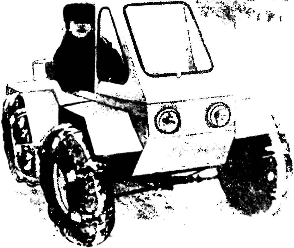
 The work of our circle of technical creativity at the Polytechnic of light industry does the city have repeatedly told on the pages of “M-K.” At the last such publication number 2 for the year 1989 drew attention to the gas company from the village of Urengoy and Tyumen region appealed to us to develop and manufacture universal all-terrain vehicle. They needed a reliable and easy-to-use machine, with its high traffic, quite comfortable conditions for the members of its crew, as well as buoyancy.
 The creation of such a vehicle required a whole year of hard work. Of course, we are talking about our creation as an industrial design, perhaps prematurely. Nevertheless, the machine was very successful, and its design is fully consistent with the resulting contact technical task. By the way, this ATV is quite suitable as a universal agricultural machine as PTO existing building-block allows the vehicle with active trailed agricultural implements.
It should be noted that the level of technology inherent in the design process, is provided on the one hand, simple design scheme, and on the other – a high degree of utilization of parts, components and assemblies production cars, scooters and sidecars.
The most crucial part of the all-terrain vehicle chassis assembly – the rear axle. That depends on him the reliability and performance of the assembly. For its foundation in our case, we took the rear axle of the car “Moskvich-408”. In principle, it could be used without any alterations, but it significantly increased the mass of the machine. Therefore, it was decided to leave without changing the gearbox and axle beam (by the way, we found it in a landfill) is significantly modified. To do this, cut the mounting flanges, brake drum, and in their place the housing welded rear axle bearings from cycle-FDD, which are established and brake drums from the same cycle-cars. Axles are made of steel with their own brand of “45”. They must be mounted flanges, which are mounted onto the studs M12 rear-wheel all-terrain vehicle. To prevent oil from getting into gear to brake drums, protective seals are mounted on the bearing housings. The brackets of the rear axle mount were cut – instead of new welded at a distance of 820 mm along the axes of the holes. Now the bridge is fixed with four M10 bolts to the engine frame, welded from thick-walled pipes with a diameter of 28 mm. Since the sub-frame is also easily removable (8 bolts M6) – it is very convenient for installation and repair as the rear axle and the entire powertrain.
Brake cables are taken from the cycle-cars. For fastening fittings brake cables used lugs welded to the axle beam.
It seems that it would be possible to further reduce the weight of the car by replacing the cast iron gearbox housing on a self-made, welded from sheet steel.
The engine in the all-terrain vehicle – from freight scooter “ant” type TGA-200. However, we changed it to the ignition system, the setting of the magneto. The variants and starting the engine starter, but, as experience has shown, he was still less reliable than the first. Indeed, not too difficult to capture on a long trip spare magneto, and totally unrealistic – a spare battery. Besides failure of the ignition system not only can be concealed in the accumulator.
On the sub-frame is attached to the engine brackets, one of which the chain tensioning mechanism is provided. Below the engine based on the M12 bolt head with a rubber gasket. After adjusting the chain bolt is rotated to the stop with the engine and then the Contra nut.

Fig. 1. All Terrain Vehicle “Grasshopper.”:
1 – PTO shaft 2 – frame number 6, 3 – frame of the rear axle, 4 – frame number 5, 5 – arm Kick, 6 – engine TGA-200, 7 – Magneto, 8 – fuel tank, 9 – frame number 4 of 10 removable tarpaulin roof, 11 – gear lever 12 is frame number 3, 13 – frame number 1, the 14 – frame number 2, 15 – band “pneumatics” (from “Zhiguli” car tires), 16 – clutch pedal 17 – base pedals, 18 – 19 the brake pedal – the gas pedal, 20 – silent-block 21 – the lever of the wheel suspension, 22 – lever steering linkage, 23 – rubber mat boards, 24 – rib pattern (birch, timber 20X40 mm), 25 – draft of a gear change, 26 – exhaust pipes, a 27 – block brakes (from the cycle-FDD), 28 – the brake drum (from the cycle-FDD), 29 – rear Axle ( “Moskvich 408” modified from the car), 30 – a conducted by An asterisk (Z = 42), 31 – the drive sprocket (Z = 17), 32 of the steering shaft 33 of spacer tube 34 -, the stay with two silent blocks (can be installed shock absorber motorcycle type), 35 – wheel hub, a 36 – wheel drive, 37 – rack and pinion steering (from cycle-FDD), 38 – Tie Rod.

Fig. 2. Parts and components rover body:
1 – frame number 2, 2 – frame number 1, 3 – frame number 3, 4 – cab frame (pine, rake 20X40 mm), 5 – stringer (pine, 20X40 mm rake), 6 – frame number 4, 7 – engine hood compartment (steel, thickness 1 mm), 8 – frame number 5, 9 – frame number 6, the 10 – wing wheel house (plywood, thickness 6 mm), 11 – “corner” duralumin 25X25 mm, 12 – Rooms’ frames (plywood thickness 4 … 6 mm).

Fig. 3. The front axle:
1 – knuckle, 2 – frame number 3, 3 – tube spacer, 4 – strut with silent blocks, 5 – the clutch pedal, 6 – the base of the foot controls, 7 – 8 brake pedal – the gas pedal, 9 – the lever 10 – Trailing arm.

Fig. 4. Rear axle:
1 – a brake drum, 2 – wire brake Bowden in shell, 3 – beam rear axle, 4 – driven sprocket (Z = 42), 5 – gear housing, 6 – braking traction, 7 – brake pedal.
Steering the car is borrowed from the cycle-FDD. Steering shaft passes through the gland, which is mounted on the bottom of the hull and bolted M6. The front wheels are mounted on self-made hubs.

Fig. 5. Control system:
1 – steering mechanism, 2 – Tie Rod, 3 – a steering shaft.

Fig. 6. the sub-frame:
1 – frame of the rear axle, 2 – the reference M12, 3 – a bolt of M8, 4 – gear lever 5 – draft.

Fig. 7. The clutch control mechanism:
1 – Bowden cable into the shell (“brake” on the motorcycle), 2 – clamp, 3 – Rod, 4 – the clutch pedal, 5 – the clutch lever on the engine.
All wheels are interchangeable. They used the old disks from the “Moskvich-412” car. As they got to us from scrap, then it took a small “restoration” to restore the broken mounting holes into which are inserted and welded bushings pin M12. Cameras the size of 320X406X800 mm.
The wheel is arranged similarly to the car. The tire is made of old “Zhiguli” tires. It is divided with a chisel into two equal “plates”. Support during this operation serves as a piece of wood clamped in a vise. Then, each piece being cut by chisel eight holes so that the width of the remaining projections is 50 mm. These protrusions and riveted metal backing strip from the conveyor belt 50 mm wide. Inside the tire ring inserted from the conveyor belt Ø 820 mm (2500 mm belt length) that connects to the rivets Ø 8 mm in the crosshairs of a cross-ties. Installation of the bus is the same as a conventional car.

Fig. 8. The hub of the front wheel.

Fig. 9. The flange of the rear wheel hub.

Fig. 10. Axle rear axle.

Fig. 11. Wheel:
1 – liner 2 – band (band of the conveyor belt), 3 – ring Ø 820 mm (band of the conveyor belt), 4 – “tire” (modified from the car “Zhiguli”), 5 – drive (the car “Moskvich” ).
Housing – a wooden, box-shaped. Frames are made from pine bruskov 20X40 mm. They are sheathed with plywood thickness of 4 … 6 mm. Closed Outside frame plywood sheets of 6 mm thickness. Fixing is made on the screws and epoxy adhesive. Also plywood Wings, they are attached to the body using aluminum “corners” M6 bolts. The body plastered with a layer of fiberglass, sanded and painted enamel.
ATV installed removable cabin, made of duralumin pipes, covered with a tarpaulin. The side panels are folded up or twisted into a roll and tied a cord. Probably a variant of a metal cabin with doors and interior heating device would be more perfect, but it will increase the weight and “overload” the already not very “strong” engine.
M. Psarev


