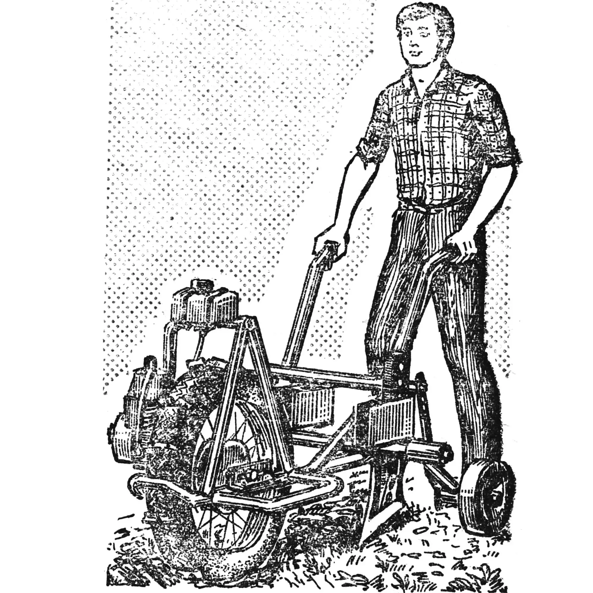
I live in Krasnoyarsk Krai. I have my own house and a small garden plot. Every spring, while digging the vegetable garden, I thought about how to ease — mechanize — this laborious work. So I decided to build a motorized plow.
I had an engine — from a motorized bicycle.
I made the frame from half-inch water pipes. I welded to it the drive wheel bracket (40×25 mm angles, 100 mm long), the reducer support (4 mm thick steel plate), crossbars with sockets for working tools, and the fuel tank fittings from an “Ural” chainsaw.
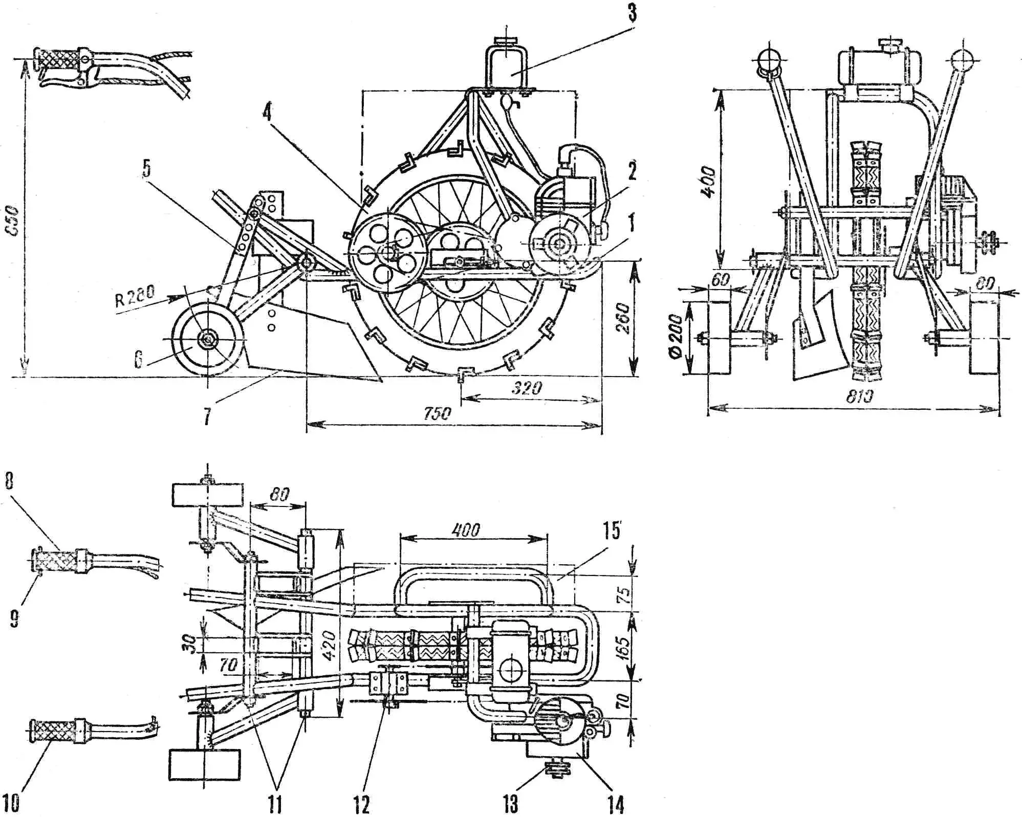
1 — frame, 2 — engine, 3 — fuel tank, 4 — wheel with ground grips, 5 — plowing depth adjustment rail, 6 — support rollers, 7 — plow, 8 — control handle with clutch lever, 9 — clutch lever lock bracket, 10 — throttle control handle, 11 — crossbars, 12 — reducer, 13 — starter pulley, 14 — fan housing, 15 — ballast box location.
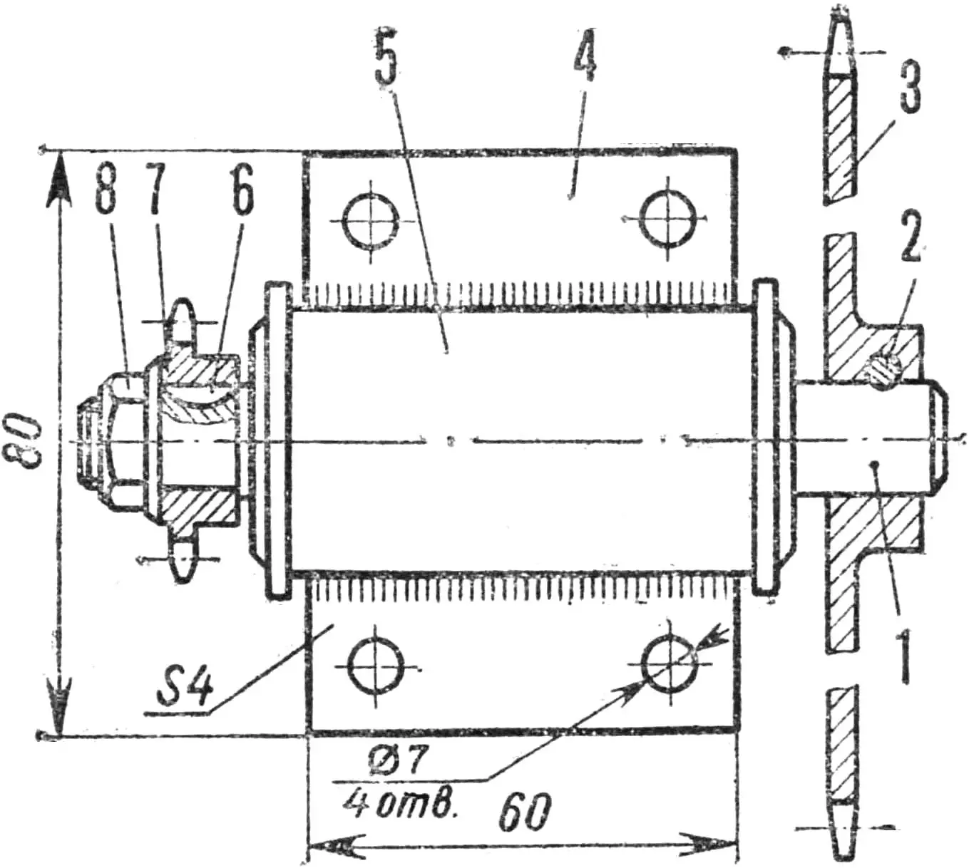
I mounted the engine in the fork of the frame tubes on points reinforced with tube sections. To prevent overheating, I fitted a forced-air cooling system — a simple centrifugal fan. I attached a homemade impeller to the end of the engine crankshaft. For this I turned an axle and replaced the standard screw that secures the clutch drive gear. I brought the axle out through a hole in the clutch cover, put the impeller, starter pulley and taper nut on it (the impeller bushing and pulley are connected by a pin to prevent them from rotating relative to each other). I riveted the fan housing, which directs the air flow onto the cylinder fins, to the clutch cover.
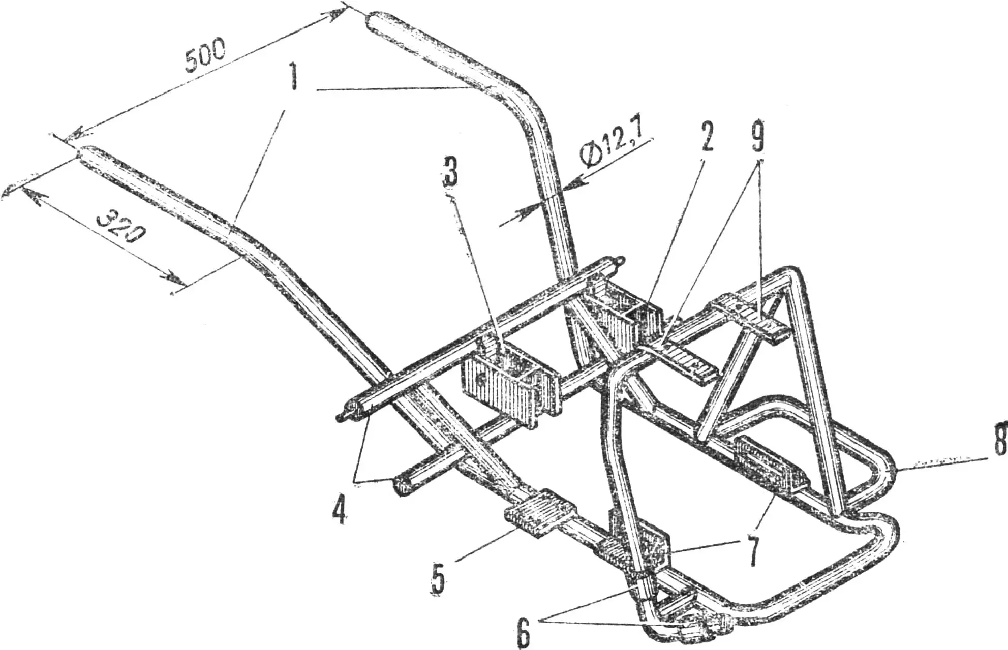
1 — handrails, 2 — left socket, 3 — center socket, 4 — crossbars, 5 — reducer support, 6 — engine mounting points, 7 — drive wheel brackets, 8 — ballast box bracket, 9 — fuel tank shelves.
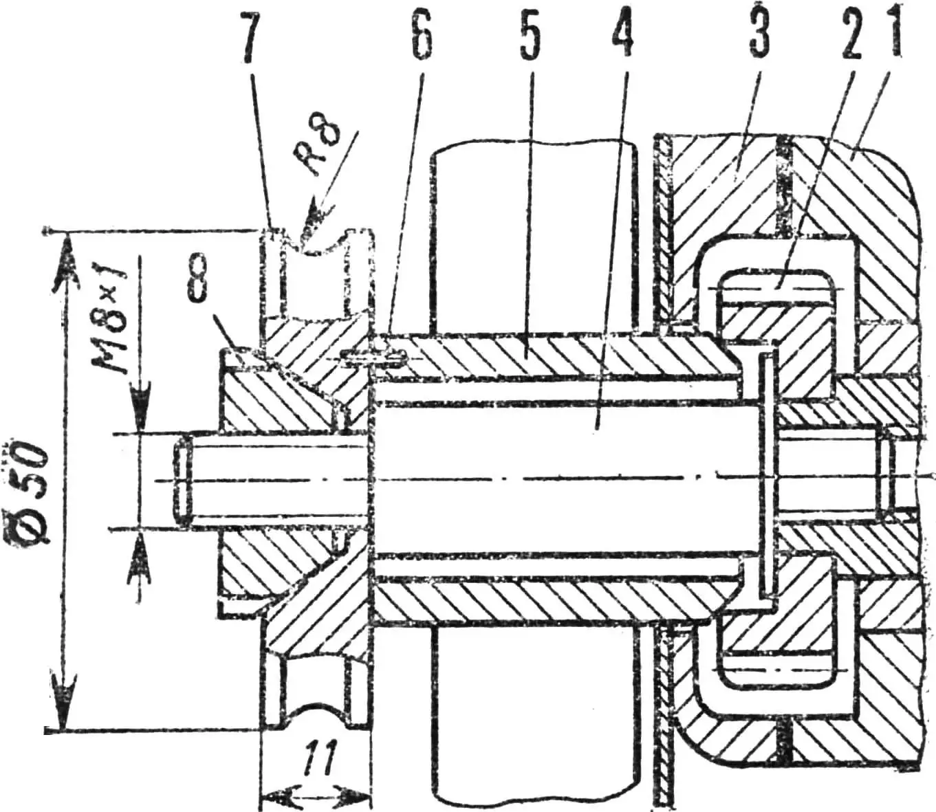
Torque from the engine, started with a rubber cord, is transmitted by chain to the reducer, which is a bicycle pedal unit cut from the frame and modified. The modification is as follows. I removed the pedals and kept the 48-tooth sprocket on the right end of the shaft. I adapted the opposite end to the D5 engine’s 10-tooth output sprocket: turned the seating and keyway, cut the thread.
Then I welded a 4 mm thick steel plate to the reducer bushing and bolted it with four M6 bolts to the support on the frame.
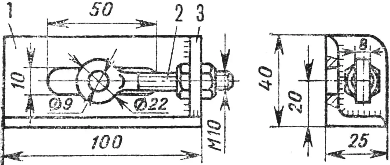
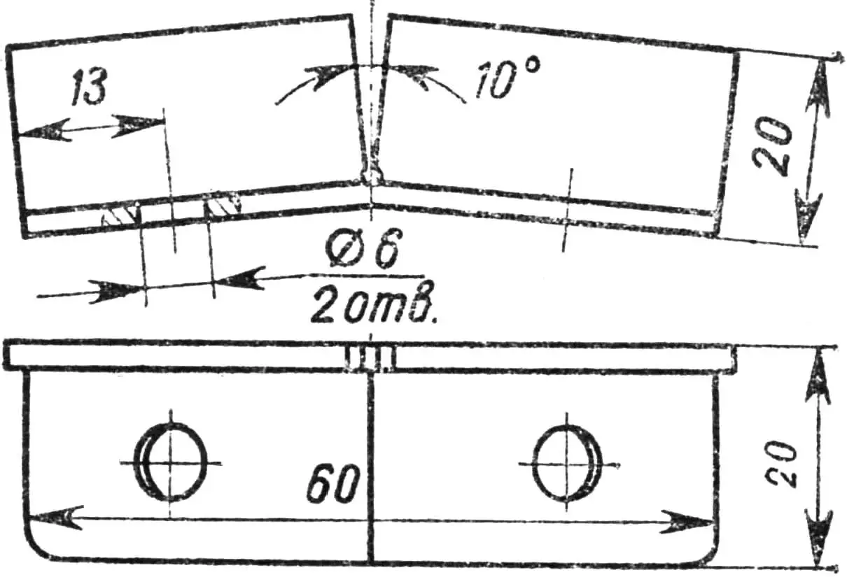
1 — angle, 2 — tension bolt, 3 — support wall.
From the reducer the chain goes to the wheel from a “Verkhovina” moped, wrapping around the bicycle pedal sprocket which I welded to the wheel’s standard sprocket. To prevent wheel slip during plowing, I attached 14 ground grips to the tire — 20×30×60 mm angles. I used M6 bolts with wide spherical heads to fix them so as not to damage the inner tube.
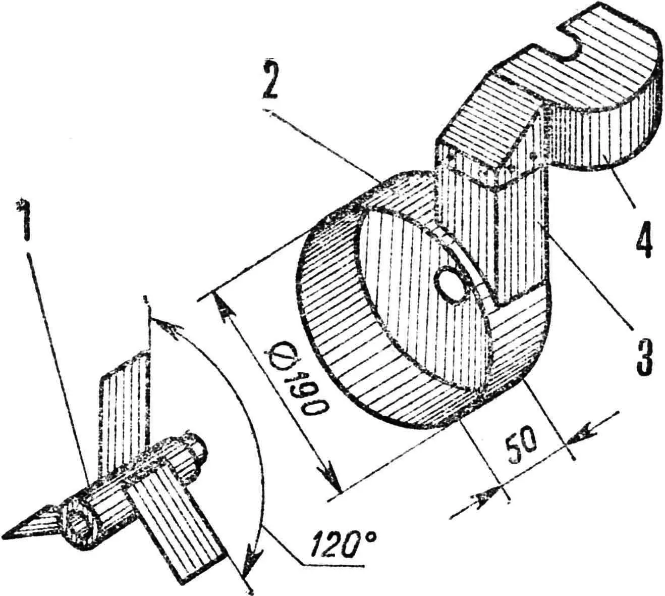
1 — impeller, 2 — impeller housing, 3 — air duct, 4 — cylinder housing.
On the left side of the motorized plow I placed a wooden ballast box on a 1/2″ pipe bracket; I load it when plowing to increase the unit’s weight and improve grip on the soil.
1 — crankcase, 2 — clutch drive gear, 3 — clutch cover, 4 — special axle with washer, 5 — impeller bushing, 6 — pin, 7 — starter pulley, 8 — taper nut.
I fixed the working tools in the sockets on the crossbars: one on the left, one in the center. The first socket is for the plow (a slightly modified fore-plow) and the second for a cultivator shank or hilling plow. At first I plowed with the plow in the center, running the wheel on unplowed land. However it was hard to keep direction. I had to make the left socket and run the wheel in the furrow.
1 — shaft, 2 — sprocket fixing pin, 3 — pedal sprocket, 4 — support plate, 5 — pedal unit, 6 — Woodruff key, 7 — D5 engine sprocket, 8 — nut.
I attach support rollers to the side of the crossbars to adjust plowing depth. They add stability and reduce the load on the arms. The right roller should be slightly wider than the left because it runs on plowed soil. When I use the cultivator, it is mounted in the center and I remove the rollers entirely so as not to damage the plants.
I took the clutch and carburetor throttle control handles from a “Voskhod” motorcycle, and the cables from a motor scooter. Behind the clutch handle I drilled a through hole Ø 4 mm in the handrail and inserted a bracket to lock the lever in the released position (when starting the engine).
The motorized plow plows light soils well to a depth of 12–18 cm. At greater depth the engine’s lack of power and its low weight become limiting.
“M-K” 8’84, S. KUZNETSOV
Recommend to read
 THE JOINT WILL BE PERFECT
When carrying out carpentry work, especially in the manufacture of panel furniture, one of the most common operations and uncomfortable — butt connection of wall. It is necessary to... HOW TO ACHIEVE THE STEREO EFFECT
Music lovers understand the interest shown by people of different ages and professions to all new in the field of stereophony. The development of electronics and improvement on the basis...
