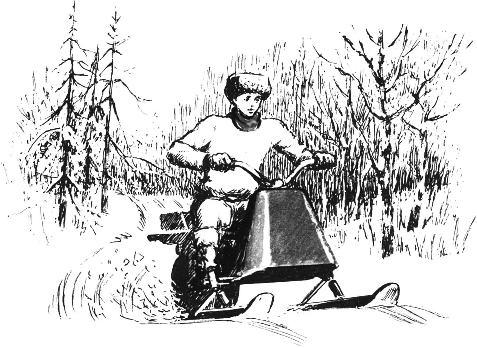
During the winter season, motor-sport enthusiasts experience a period of relative calm. The reason is the poor conditions in which the rider finds himself: once he rides his two-wheeled “friend” onto a snow-covered road, sometimes with ice patches. And off-road you can go only on a specially prepared motorcycle (with studded tires).
Using the idea proposed by Yu. Baukov, you will build a machine well suited for various winter sports and recreation. It will replace both a traditional kart in circuit races on flat tracks and a motocross motorcycle in off-road competitions, because it has remarkable stability and off-road capability. With its own mass of about 70 kg, the snowkart easily reaches speeds up to 50 km/h. It can be used in summer as well, installing wheels instead of skis.
The snowkart is a three-support wheel-and-ski vehicle powered by a T-200 engine from the “Tourist” scooter. This is one of the most reliable domestic two-stroke engines, equipped with forced air cooling, a powerful starter, and a generator.
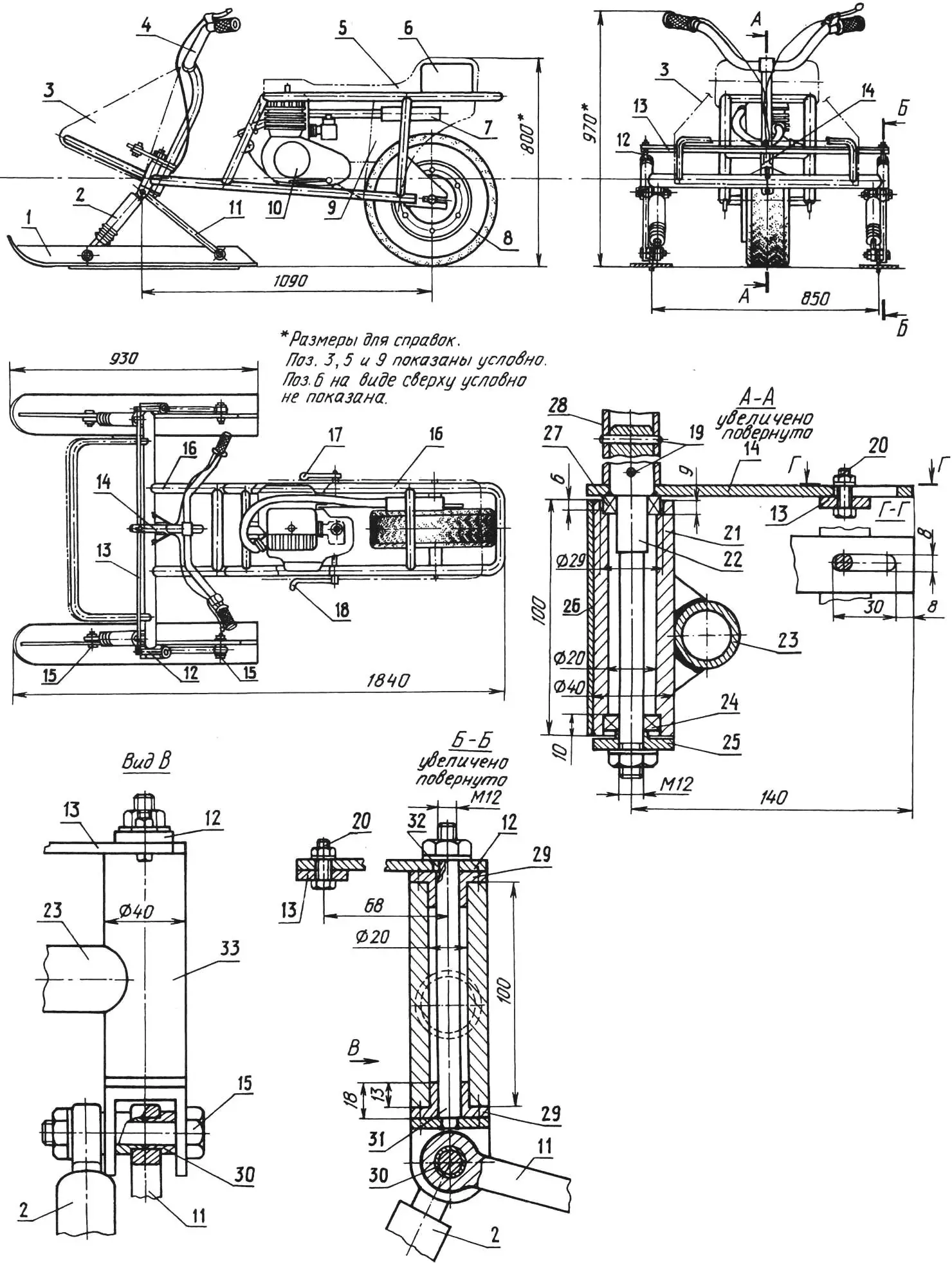
1 — ski, 2 — shock absorber, 3 — fairing, 4 — handlebar (from a “Salute” type bicycle), 5 — seat, 6 — fuel tank, 7 — muffler, 8 — wheel (5×10″), 9 — side guard, 10 — T-200 engine, 11 — tiller, 12 — steering linkage drive (steel 45, sheet s5, 2 pcs.), 13 — steering bar (steel 45, sheet s5), 14 — steering fork (steel 45, sheet s5), 15 — axle (M12 bolt, 4 pcs.), 16 — frame, 17 — brake pedal, 18 — gear-shift pedal, 19 — pins (steel 45, rod Ø5), 20 — stepped bolts M6, 21 — main steering column housing (St3), 22 — steering shaft (steel 45), 23 — frame cross beam, 24 — bearing 101, 25 — cover (St3), 26 — gusset (St3, sheet s2), 27 — bearing 8102, 28 — steering post, 29 — supporting bushings (bronze), 30 — bushings for mounting the tiller (bronze), 31 — steering support shaft (St3), 32 — key, 33 — housing of the front-support steering column (St3).
The all-terrain vehicle’s spatial welded frame is made of steel pipes with a diameter of 32 mm and consists of a transverse beam on which are mounted the housings of the steering columns of the front supports and the steering column, two longitudinal rails (longerons), and a seat subframe, connected to each other by a pair of struts and braces. In addition, the frame is reinforced with several cross members and gussets, and it is protected from a head-on impact by a bow/arc that also serves as the mount for the fairing. Side shields that partially cover the wheel are intended to prevent the rider’s clothing from getting into the chain or under the wheel, and to strengthen the cantilever part of the seat subframe.
To simplify the frame assembly process and ensure greater accuracy, it is best to use the simplest jig/fixture, where all frame elements are rigidly fixed according to the working drawing.
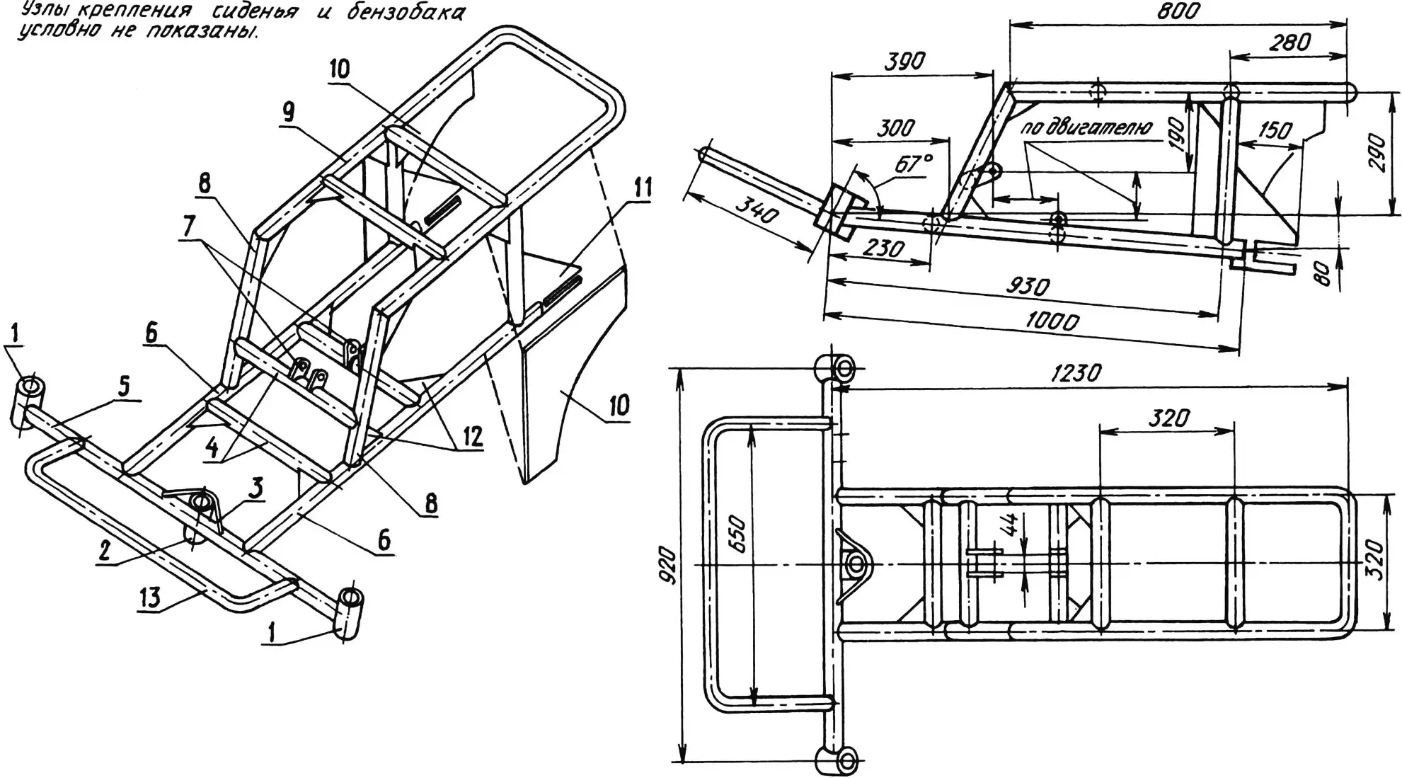
1 — housings of steering columns of the front supports, 2 — main steering column housing, 3 — encompassing gusset, 4 — cross members (pipe 32×2.5, 5 pcs.), 5 — transverse beam (pipe 32×2.5), 6 — longerons (pipe 32×2.5), 7 — engine mounting brackets (sheet s5), 8 — braces/struts (pipe 32×2.5), 9 — seat subframe (pipe 32×2.5), 10 — side shields (sheet s1.5), 11 — wheel mounting bracket (sheet s5), 12 — gussets (sheet s2), 13 — fairing subframe arc (pipe 21×1.5).
Machined housings of the columns are welded to the transverse beam at an angle of 67° to the plane in which the longerons are located. The attachment of the middle housing for greater rigidity is reinforced with an encompassing gusset.
The steering column shaft rotates in two bearings. Its upper part is turned to the internal diameter of the steering post and fixed in it with two pins. The steering fork of the steering mechanism is welded to this same part. When the handlebar is turned to one side or the other, it rotates both steering link drives of the front supports simultaneously through the bar. The link drives strengthened on the steering shafts of the supports using keys provide the corresponding steering angle of the tiller and the skis. In the support columns, instead of bearings, bronze bushings are used (capron or PTFE bushings may be installed). The support shaft has a lug that is used for mounting the shock absorber and the tiller. The latter are placed on a common axle also through bronze bushings and washers. Standard from a moped are used as shock absorbers of the front supports.
The driving wheel is installed in special brackets made of sheet steel, placed in the cuts of the longerons and then welded to them and to the frame uprights. The wheel is taken from the S3D motor scooter, but with an enlarged rim. How it is enlarged has already been described in our publications. Briefly, here they use the fact that the rim structure is detachable and, if necessary, additional gaskets/spacers are installed between its halves. A brake drum and a driven sprocket are mounted on the same rim. The driven sprocket can be either the standard one from the “Tourist” scooter or homemade—everything depends on the maximum speed you plan to reach on your snowkart.
The engine is fastened to the frame at the standard front and lower mount points. For this, matching brackets are welded to the corresponding cross members of the frame. To ensure accuracy of mounting these parts—and to temporarily fix them—first you bolt/position the brackets on the engine (which is then installed onto the frame) and tack-weld the brackets. After that, you check that they are installed correctly (the driving and driven sprockets should be in the same plane), remove the engine from the frame, and finally weld the mounting parts.
The exhaust pipe and muffler are routed under the seat. There is enough space there to place them, and they end up in an area that is difficult to reach and safe for the rider. They are secured with clamps and brackets.
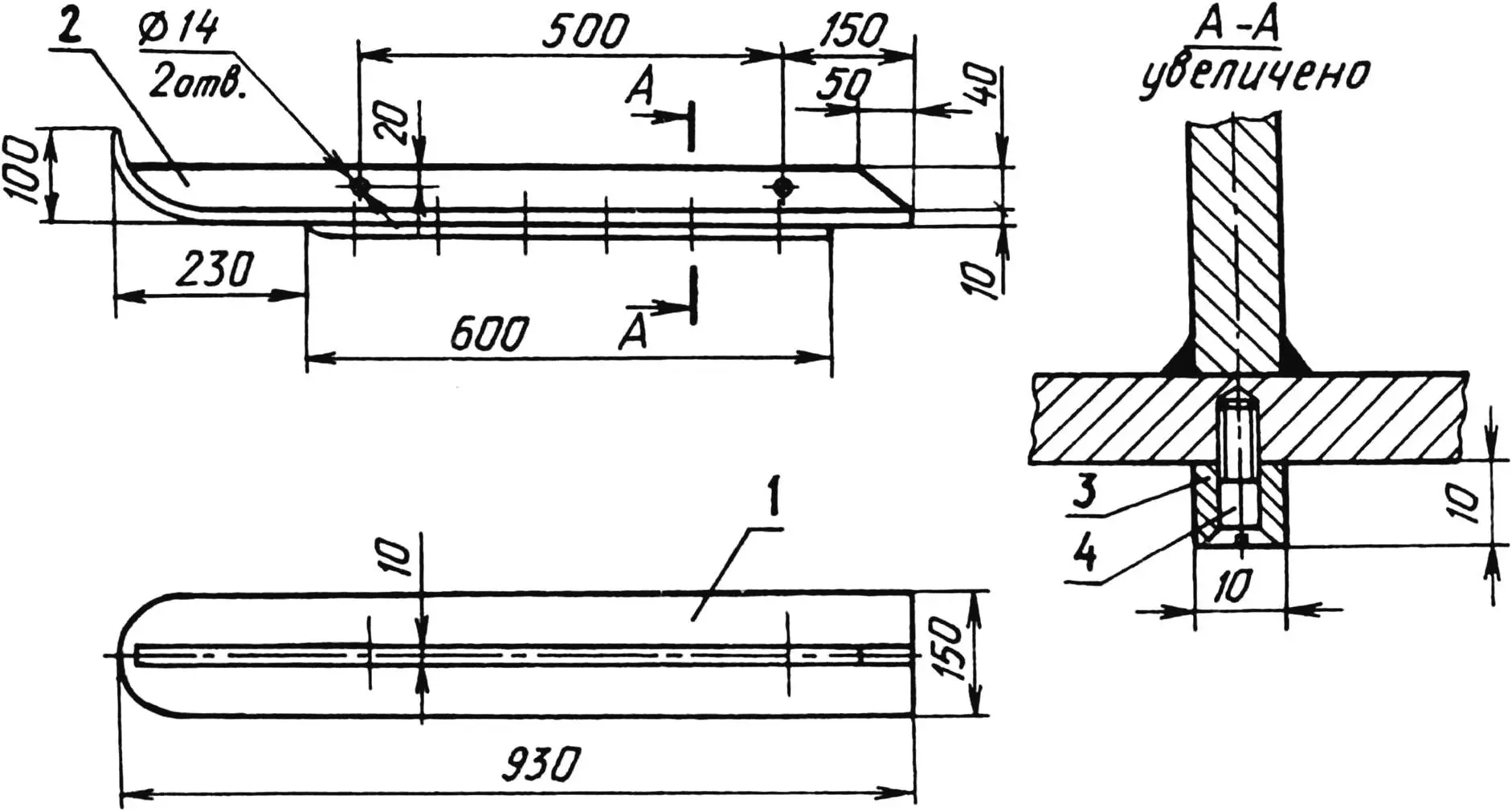
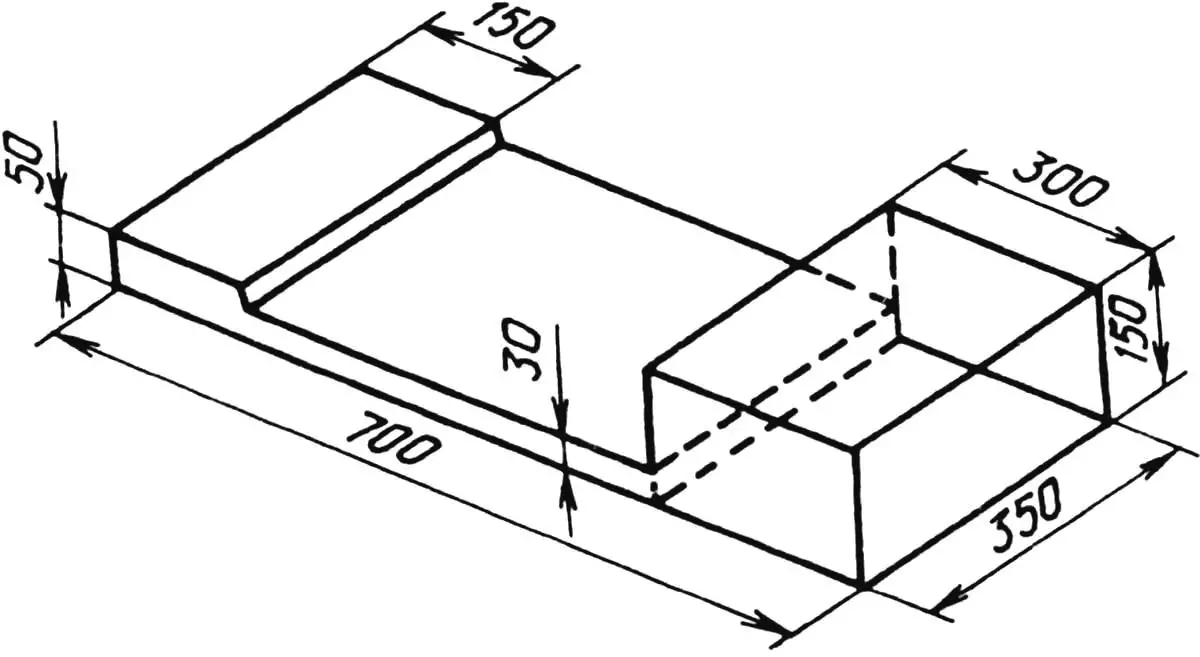
1 — sole, 2 — stiffening rib, 3 — cut edge, 4 — screw M5 (6 pcs.).
The snowkart ski consists of a sole, a stiffening rib, and a cut edge. The first two parts are cut from a duralumin sheet and welded together in an argon environment; it is desirable for the third part to be removable. This is necessary because the cut edge wears out rather quickly and must be periodically replaced or re-ground. In addition, such a design makes it possible to use cut edges of different heights—depending on the thickness and condition of the snow cover (freshly fallen or packed snow, crust, or even ice). As for the stiffening rib, it also serves as the bracket to which the shock absorber and tiller are attached.
Making the seat should not cause major difficulties, since it is based on a plywood frame with raised sections: in the front part—covering the cylinder head slightly projecting above the subframe, and in the rear part—for the fuel tank. The frame, glued with foam rubber and covered with artificial leather, is securely attached to the subframe using quick-release locks or several bolts.
The car’s special appeal will be the front fairing, painted in bright colors, mounted on the arc subframe with self-tapping screws. It is best cut from thin sheet duralumin, carefully bent along the leading edge, and the seams welded.
“Modelist-Konstruktor” No. 12’97, V. KUDRIN
Recommend to read
 SELF-PROPELLED ON WHEELS
The first attempts to improve operational mobility artillery through the installation of various caliber guns on tracked or wheeled chassis has been made at the beginning of XX century.... SPIKES? NO PROBLEM
Most comfortable furniture, "serious" joinery collect connecting parts on the thorns. Technical requirements for the quality of such nodes is usually very high. Run them by milling or...
