
A combined tabletop circular saw is needed by every model-makers’ club. It makes it easier to carry out a whole range of woodworking tasks; in addition, by replacing the tool on the bench, you can sand wooden parts, polish metal surfaces, and sharpen tools.
To make such a machine, you need a single-phase electric motor rated at 150—200 W, running at 2500—3000 rpm, or a three-phase motor in which two of the three phases are combined through a “paper” capacitor with a capacitance of 20—40 mF, rated for 500—600 V. Motor reverse is achieved by switching phases.
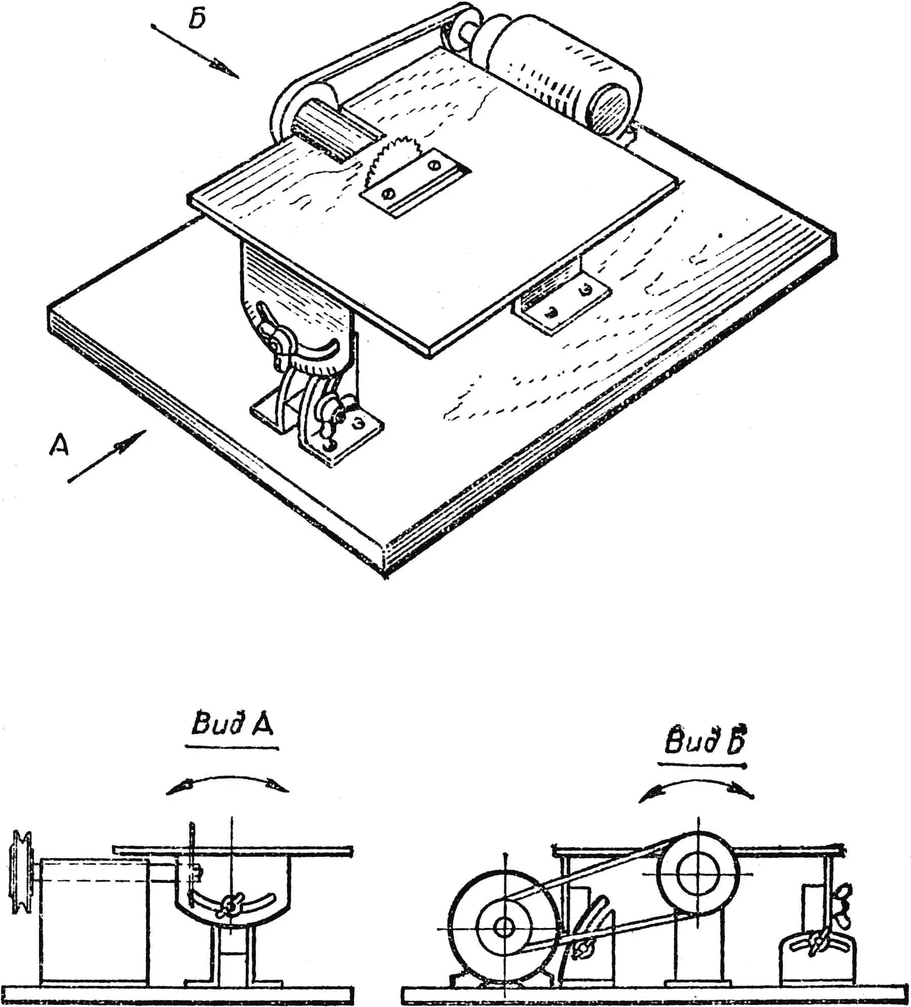
The design of the circular saw shown in Figs. 1 and 2 is intended for an electric motor whose shaft extends from both sides of the housing.
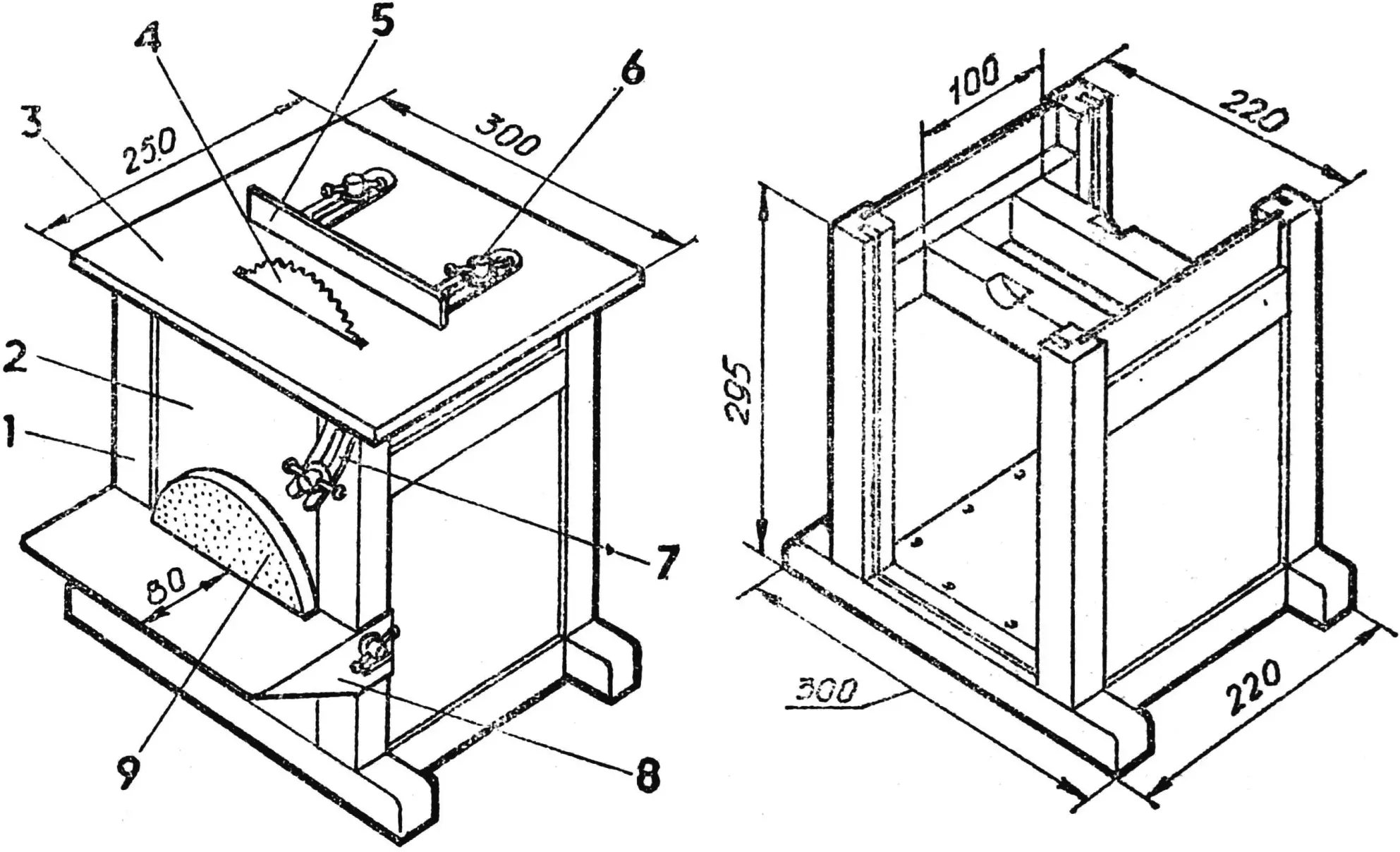
1 — base frame, 2 — sliding wall (plywood), 3 — table top (plywood), 4 — disc saw or milling cutter Ø 120 — 150 mm, 5 — guide ruler (steel), 6 — clamping screw with washer, 7 — guide (steel), 8 — bracket (steel), 9 — sanding wheel.
Disc saws are installed on the machine, and if they are not available, you can successfully use disc milling cutters — Ø 75—150 mm and 0.8—1.5 mm thick.
The machine base frame is made from timber blocks of hard wood, 30×30 mm in cross-section, and is assembled into a glued mortise-and-tenon joint. Two side walls cut from 4—5 mm thick plywood are glued into a groove machined in the blocks. The other two walls are sliding, and one of them has a slot for the motor shaft.
On the lower frame of the base, a 10 mm thick base is attached. The electric motor is mounted on it with bolts and nuts.
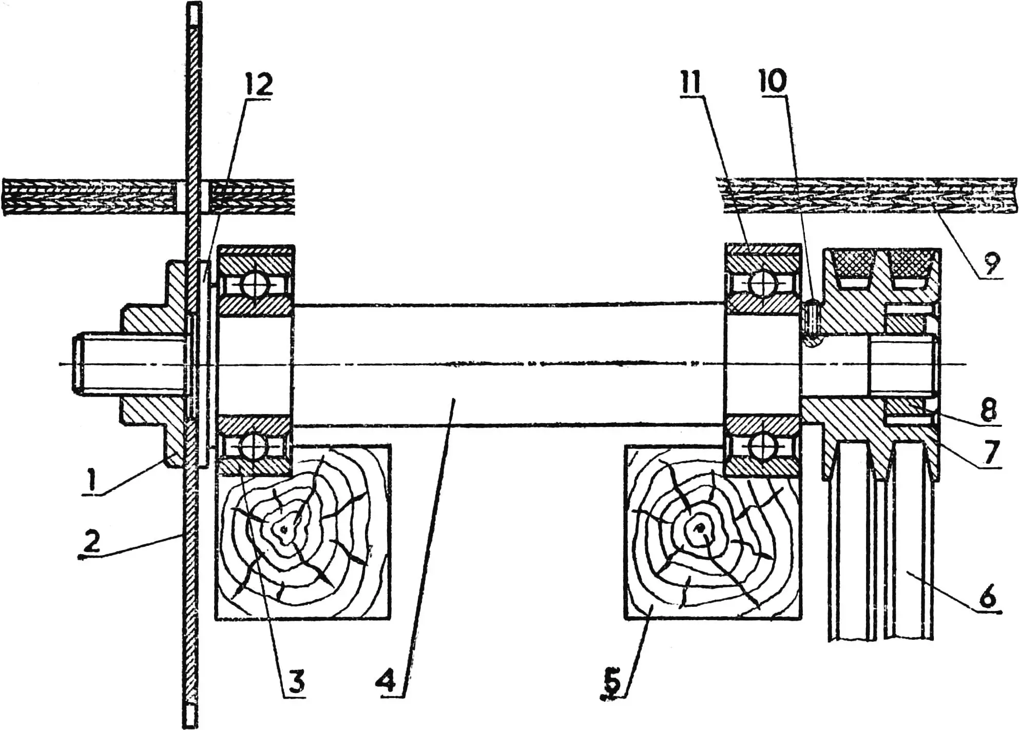
1 — clamping nut, 2 — disc saw (milling cutter), 3 — bearing, 4 — shaft, 5 — base frame block, 6 — drive belt, 7 — pulley, 8 — nut, 9 — table top, 10 — clamping screw, 11 — bearing housing, 12 — stepped washer.
The dimensions of the base frame are determined by the motor size. One end of the shaft should protrude outward — to mount a sanding or polishing wheel.
The upper connecting blocks of the base frame serve as a support for the saw shaft. At the places where they are installed, recesses are chiseled to a depth of 5—6 mm. The bearings are radial, single-row, with an inner diameter of 12—15 mm and an outer diameter of 40 mm; they are fastened with brackets made from 2— 3 mm thick sheet steel.
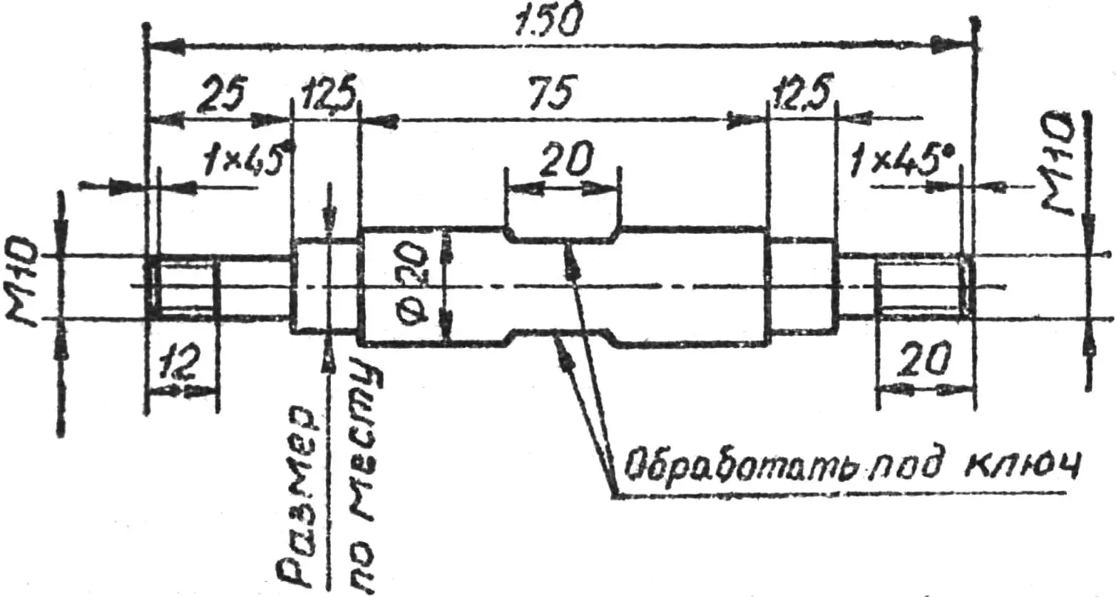
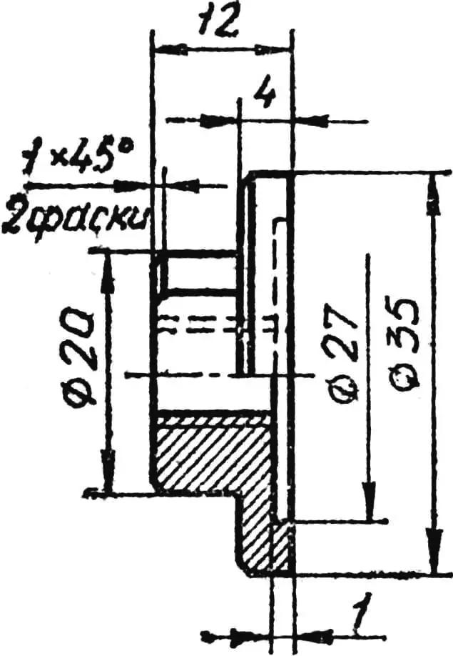
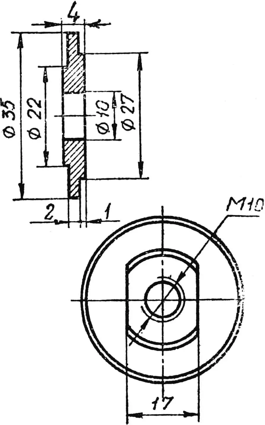
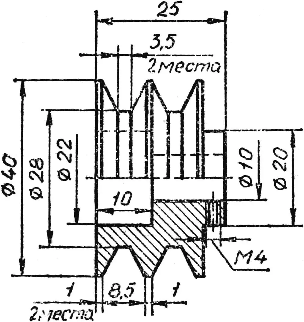
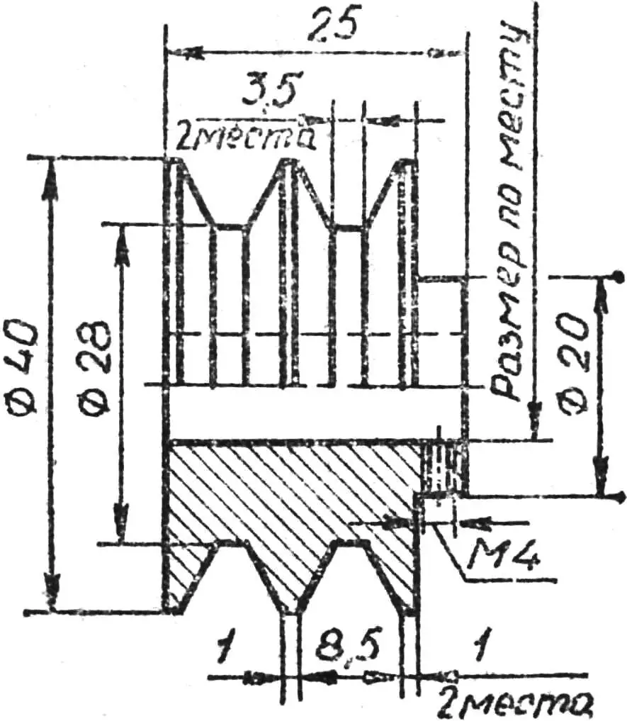
The shaft, pulleys, the stepped washer for the cutter, and the nuts are machined from steel. The shaft journals are fitted to the inner diameter of the bearings.
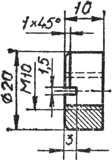
On the washers, two flanges are made for holes in the cutters of Ø 22 and 27 mm, or else according to the inner hole diameter of the disc saw. This design makes it possible to use one washer for various cutters.
The pulley is fixed on the electric motor shaft with a locking screw M4.
To make the rails on the circular saw table, a movable guide ruler is secured with two clamping screws.
Adjusting the height of the disc saw for cutting grooves and tenons is done by lifting the table. The table is made from 6—8 mm thick plywood, plastic, or 4—5 mm thick sheet metal. One side of the table is hinged to the base frame supports on hinges (up to 30 mm long); the other side is supported by arcs with slots through which two clamping screws M5 with washers pass.
Drive belts are tensioned between the pulleys of the circular saw and the electric motor. For this, you can use a belt of round cross-section from the drive of a foot sewing machine.
To remove sawdust under the saw disc, a gutter bent from tin is attached to the base. At the gutter exit point in the plywood wall, a window is cut.
For sanding wooden items, a removable flange is placed onto the motor shaft, to which a plywood washer with coarse-grit sandpaper glued on is attached with four screws. The flange with the washer is fixed on the electric motor shaft with a locking screw.
On the sanding wheel you can process not only flat surfaces, but also parts with external radii of rounding.
To the base frame of the circular saw, a removable bracket made from 2—2.5 mm thick sheet steel is fixed with two screws and washers. It serves as a stop for the part being sanded. At the locations of the bracket feet, strips are cut in and fastened with screws to the base; each strip has a guide pin that prevents the bracket from rotating.
When polishing parts, instead of the sanding washer you install a polishing wheel on an adapter. The adapter with the polishing wheel is placed on the electric motor shaft and secured with an M4 screw. The diameter of the polishing wheel for a motor running at 2500—3000 rpm is 100—150 mm.
The polishing wheel is made from individual square pieces of burlap or other cotton fabric, stacked one on top of another, as shown in Fig. 9. The grain direction of each subsequent layer must not coincide.
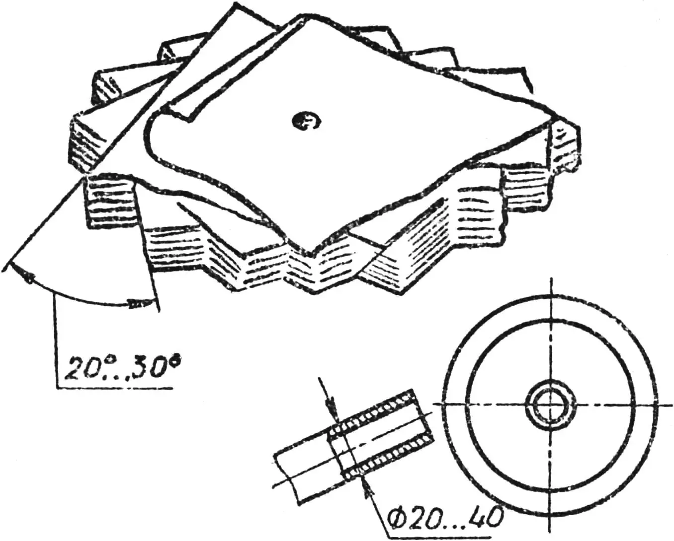
A new polishing wheel is placed on the motor shaft and, with the electric motor running, its surface is leveled using a pipe offcut (Fig. 9). Individual ends of the threads are separated, while the others are frayed around the circumference. Polishing paste is applied to the wheel, and you can begin polishing parts. To avoid accidents, the parts being polished must not be held by hand. They should be firmly secured in mandrel holders, exposing only the polishing surface.
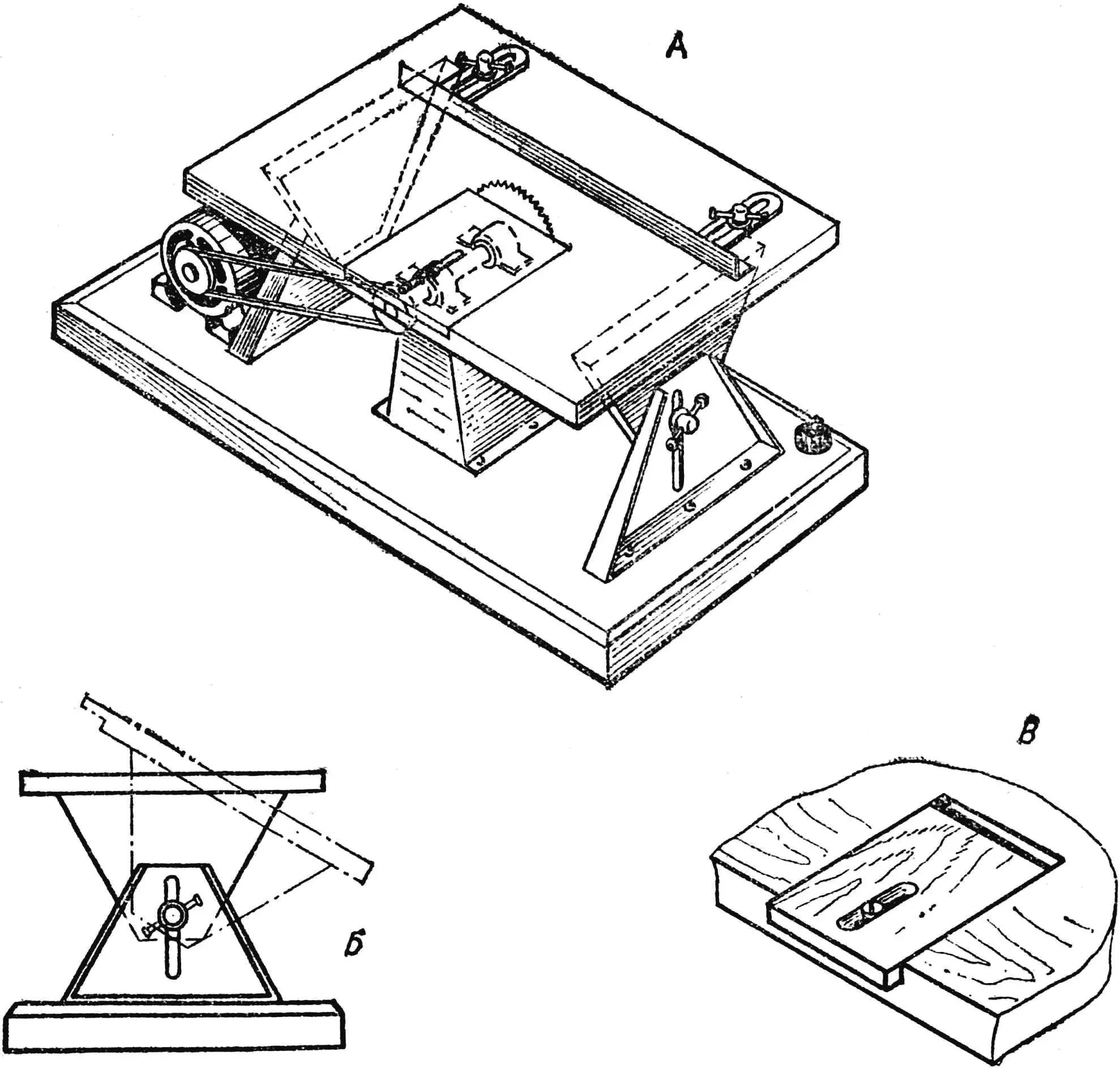
A — general view, B — table rotation scheme, C — adjustable table slot.
By mounting a small emery wheel on the electric motor shaft, you can sharpen tools and grind metal parts.
If the electric motor has only one end of the output shaft, the polishing wheel is placed in the place of the disc saw. In this case, the table is made removable.
«M-K» 10’76, A. KOCHERGIN, A. EFIMOV
Recommend to read
 QUIET “LITTLE ONE”
Most amateur constructors are constrained not only in space (usually they have only a small corner in their apartment for pursuing their favorite hobby), but also in time (they can...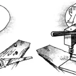 Drill press made from… boards
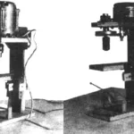
It is generally accepted that the drill is the main tool of home handymen, hobbyists who like to build things with their own hands for the home and family, and also the primary means of...
