 In Amateur practice when developing or building a device often require multiple power sources at different voltages. For example, structures made in operational amplifiers and working in conjunction with digital integrated circuits require the bipolar and unipolar current sources. To use in such cases, the voltage divider is uncomfortable, especially in the process of developing new devices. After all, it is necessary to change the number of elements used and their type, which leads to a change of energy parameters of the device, and hence to necessity of the divider.
The following power supply is largely generic and basic operational characteristics meet the requirements for such devices. It is powered by AC voltage 220 V, power consumption does not exceed 200 watts.
The structural unit constructed according to the functional-modular principle. Each module is a structurally complete device, perform specific functions.
The block contains four separate voltage regulator, switching which it is possible to obtain different combinations of current sources. Each stabilizer has it’s own on the adjustment of the output voltage and is equipped with an electronic protection system against overcurrent and short circuit, which is assembled on the chip DA1 and works as follows. If you increase the voltage drop across R16 caused by the increase of the load current, the increasing positive voltage at terminal 4 DA1, which reduces the voltage at pin 9 DA1 and opening VT2, then, in turn, VS1 and VT1; this triggers the relay K1, disconnecting all the loads from the stabilizer.
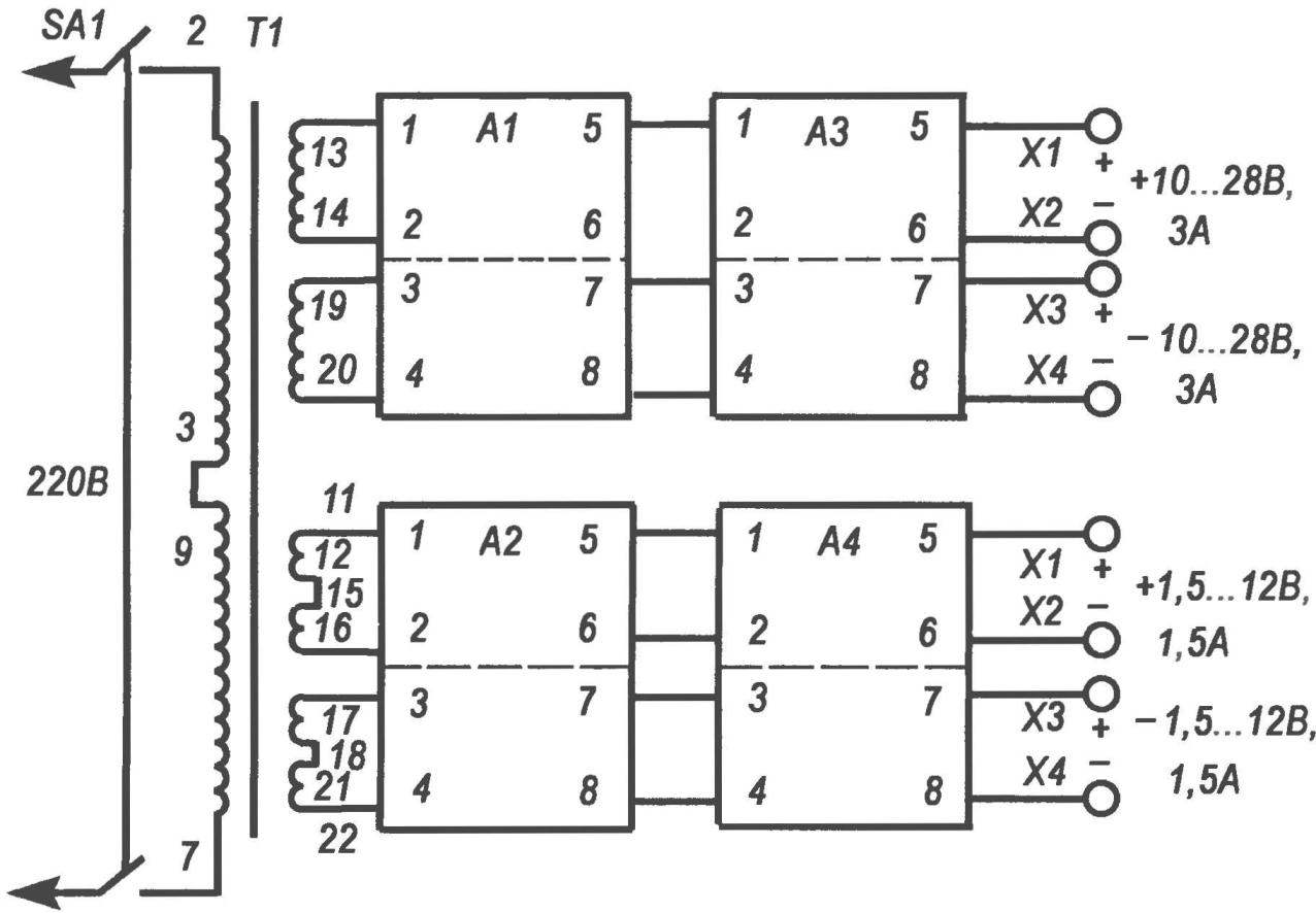
A block diagram of a modular power source:
the transformer T1 — TPP 322-50 or similar. having two secondary windings 30 (3 A) and two windings 13 In (1.5 A); switch SA1 — brand TP 1-2 or T3
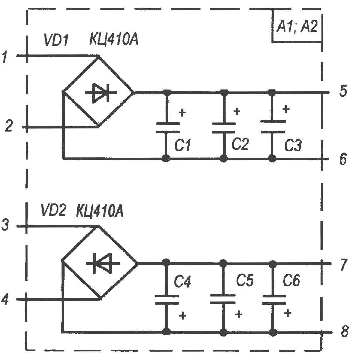
Diagram of bridge rectifier modules A1 and A2. The difference in execution modules:
A1 the values of the capacitors C1 —C6 2200 UF x 50 V; A2 the values of the capacitors C1—C6 1000 µf × 25 V (type all condensers — K50-29 or K50-24)
The speed of response of protection does not depend on the detail sliders to R14 and R11. For normal operation of the VS1 is R4.
Diode VD1 prevents the breakdown of VT1 reverse voltage windings K1.
Pressing the SB1 button “Reset” is the closing VS1 relay K1 and the stabilizer returns to its original working state. The “Reset” button press after disconnecting the loads from the stabilizer.
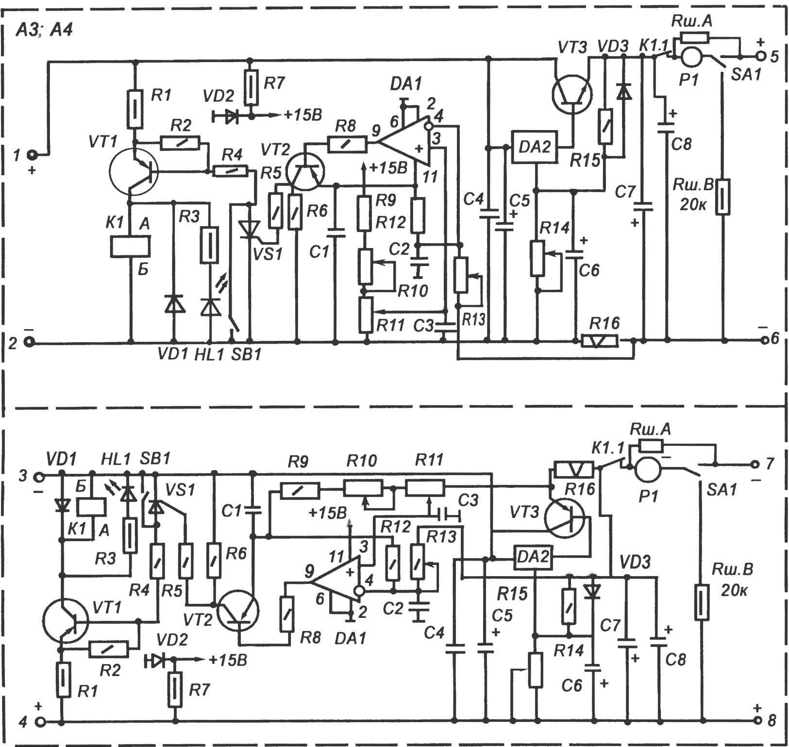
A circuit diagram of the controlled voltage stabilizer with overload protection and short circuit protection build in devices:
R2, R4, R5, R8 — 1; R6 — 100; R9, R12 is 1,1 K; R10 — 10k; R11,R14 to 4.7 K; R13—470; -240 R15; R16 — 0.1 Ohms; C1, C2, Sz, S4 -0,1 UF; C4 -0,33 UF; C5, C6, C7 -47 UF x 50 V; C8 — 20 UF x 50 In VT1, VT2 — КТ814Г; VD1, VD2 — КЦ410А, KD212A; DA1 — К554САЗ, DA2 — К142ЕН18; HL1 — АЛ307; VS1 —КУ101Г
Resistors R13 and R10 are used to adjust, respectively, the minimum and maximum current protection. The resistor R11 adjusts the current protection range from 50 mA to 3 A (1.5 A).
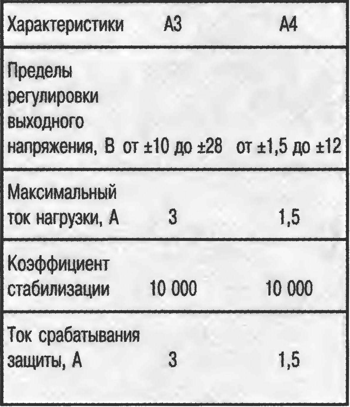
The distinction between schema elements stabilizers A3 and A4 is:
AZ: R1 — 1 kω; R3 is 2.7 ohms; R7 — 1 kω. Relay K1 type REN-34, Zener diode VD2 —type КС515А, VT3 — КТ827А. This stabilizer gives a constant voltage to ±10 — V. 28
A4: R1 is 0.5 ohms; R3 — 1.2 kω; R7 -1,1 com. Relay K1 type RES-9, a Zener diode VD2 — type КС510А, VT3 — КТ825. The output voltage of ±1.5 — 12 V. Power DA1 in this case is 10 V, which is quite acceptable.
The main technical characteristics of stabilizers
The differences in patterns of bridge rectifiers A1 and A2 only in the values of capacitors: the first one is C1 — C6 have a capacitance of 2200 µf and designed for voltages of 50 V, the second they are 1000 UF x 25 V
The power protection circuitry is derived from the Zener diode VD2 Ranges of supply voltage of the chip DA1 +5 to +20 V. the Capacitors C1, C2, C3 serve to reduce interference.
The stabilizer, assembled from known good parts, as a rule, does not require adjustment, and it is reduced only to the installation of protective current.
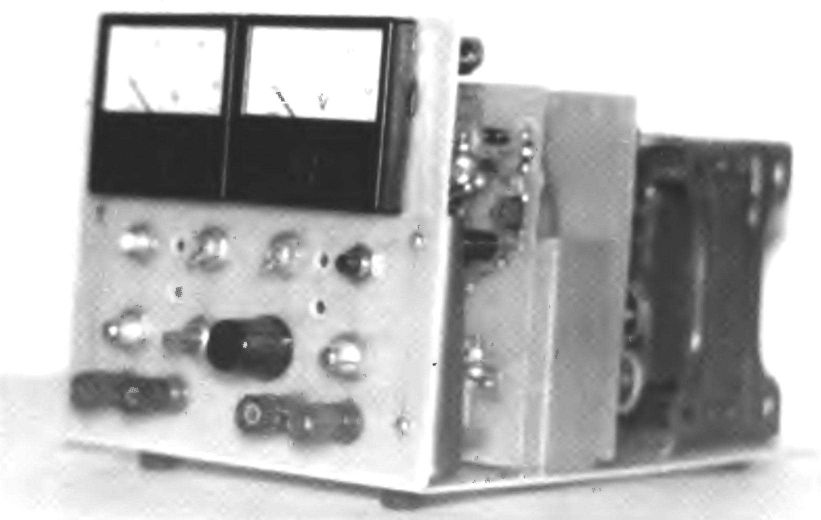
PSU design
The PSU has dimensions of mm. 260x130x250 the front panel are the measurement of current and voltage, reset protection, led indication protection. This also removed the handle of the resistors of the voltage and current of tripping the toggle switch of the devices “current — voltage”, output terminals. BP is assembled on the basis of the 10-mm vinyl plate size 260×250 mm, bottom base rubber feet are attached.
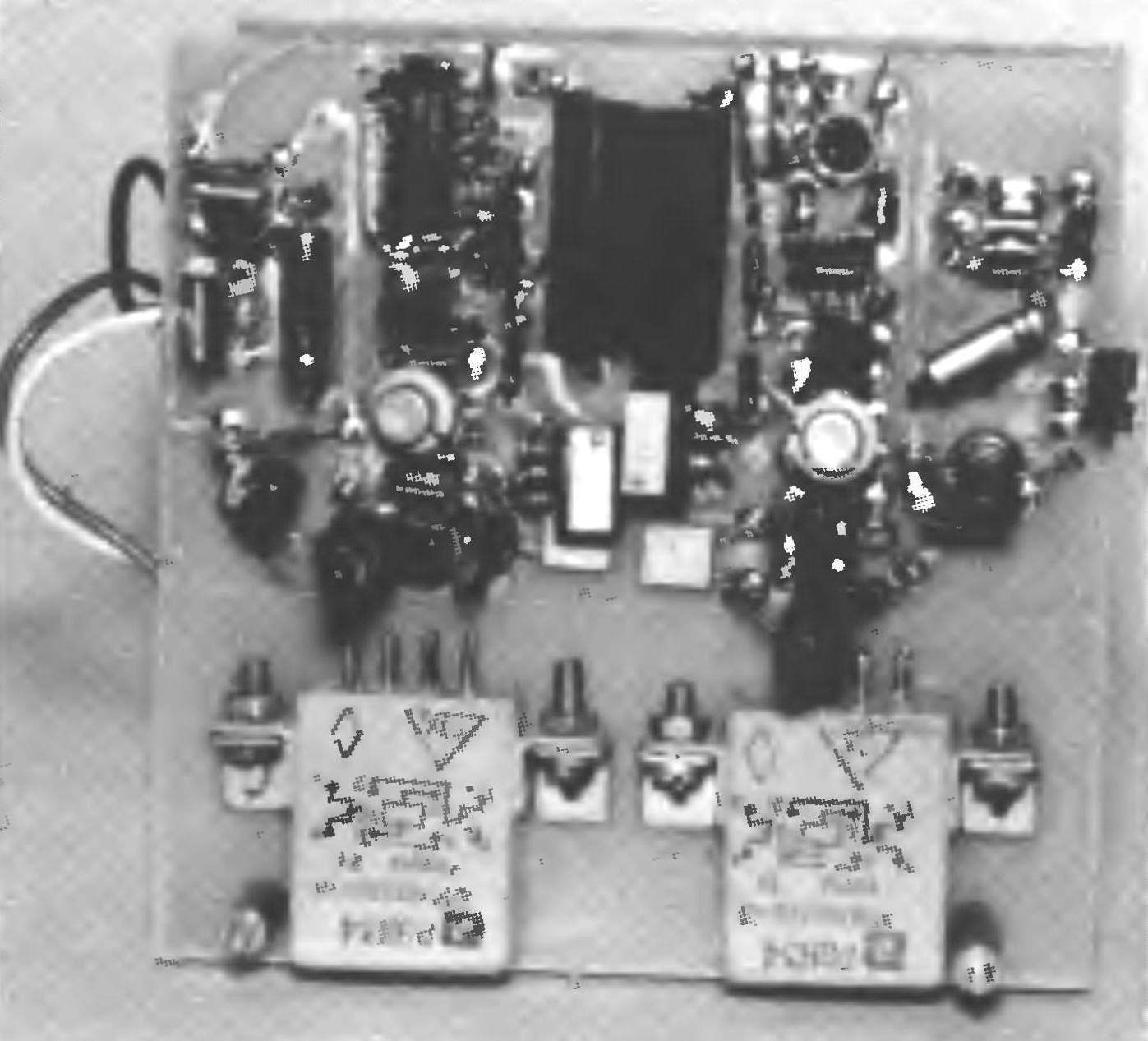
Both modules block similar schemes and designs, with the exception of certain elements. Each module consists of two printed circuit boards and radiator. Board size 120x120x2 mm of unilateral foil fiberglass. On the same Board are mounted two independent bridge rectifier, the second — two independent regulatory voltage regulator “+” and “-” with the protection circuit.
Wiring Board stabilizers
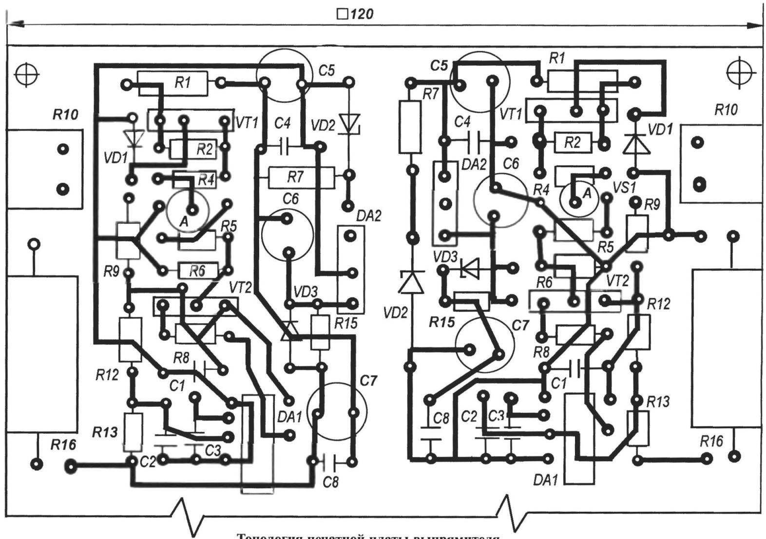
A printed circuit Board, rectifier
Radiator module size 120x120x30 mm has a rib height of 12 mm on both sides. On the radiator are fastened with paste KPT-8, two power transistors, one of which is mounted on the insulating gasket.
Circuit Board modules are screwed to the radiator with the two sides of the rack using the screws M3.
The module itself is mounted on the base unit with screws M4 (via a sleeve with a height of 5 mm in corresponding threaded holes at the bottom of the radiator). The ground under the radiator drilled holes with a diameter of 6 mm.
Installation and the modules is performed by wire MGTF (MGSV) with a diameter of 0.5 mm.
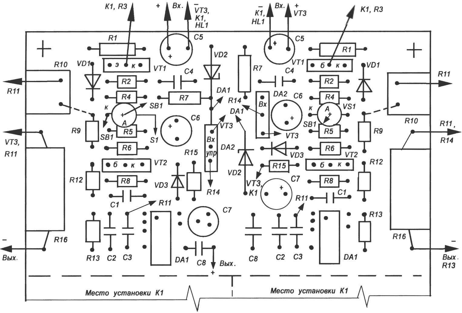
The layout of the stabilizers on the PCB
The back plate and the housing can be made of any material, depending on the capabilities and skills of the contractor.
The resistors used in the device, mostly types of MINTS, OMLT, C2-33. Resistors R16 — type JS4-1 or JS1 group A.
Resistors R10, R13 — type SP5-2.
Capacitors — KM, K10-17A, electrolytic K50-6, K50-16 or imported to the appropriate voltage.
КТ814Г transistors can be replaced by КТ816Г, КТ827А — КТ819 and КТ825 — КТ818.
Chip DА1 К554САЗ can also be replaced by К521САЗ, but be careful of the Pinout.
For stabilizer, AZ used relay K1 type REN-34 by 27 In, stabilizer A4 — relay K1 RES-48 12 In parallel with the contacts.
Button БВ1 — KM1-1. Toggle БА1 — MTZ connected in parallel.
Y. KURBAKOV, Tula
Recommend to read
 JAPANESE KA-MI WITH “SKIRTS”
In preparing attack on South East Asia command of the Japanese armed forces imagined the difficulties associated with overcoming the army of the numerous water hazards on the territory... MINI-TRACTOR “Eaglet”
The idea to create a mechanical four-wheeled assistant came after several years of cultivating a summer cottage with a homemade walk-behind tractor, which turned out to be very heavy and...
