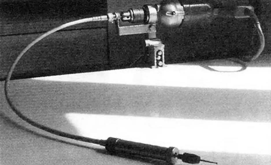
I’ll probably be right in saying that most home hobbyists dream of having a universal rotary tool at their disposal. How many opportunities it opens for its owner! Engraving, abrasive machining of parts with complex shapes, making stamps and press forms yourself, drilling and countersinking holes located in places hard to reach with a regular drill, jewelry work—this is far from a complete list of operations this mechanism makes possible. So it’s no wonder that, due to its high demand, such a tool is not easy to buy in a store.
At the same time, this mechanism can be made by yourself. I propose the relatively simple design of a rotary tool that I built based on an electric drill.
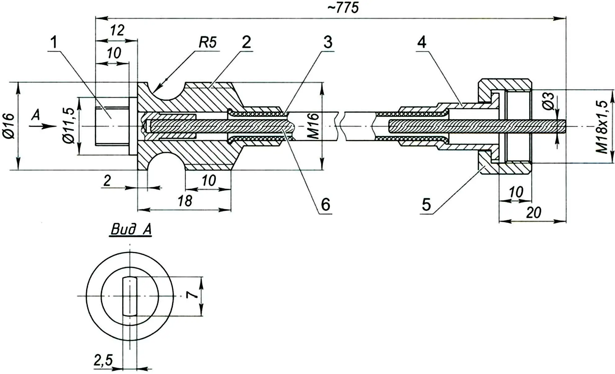
1 — shaft tip; 2,4 — casing tips; 3 — flexible casing; 5 — union nut; 6 — flexible shaft
First of all you will need a flexible drive. I recommend using a speedometer cable for this purpose—it’s easy to buy at any auto or motorcycle parts shop. I used the speedometer flexible shaft from an “IZh” motorcycle, type GV 119A-01; all the dimensions shown in the figure are based on it. This part fully met operational requirements and, moreover, required almost no modifications: I only had to cut an M16 thread on the surface of one of the casing tips (Fig. 1). With equal success, speedometer cables of other types can be used.
The appearance of the rotary tool is shown in Fig. 2. The electric drill is clamped in a vise using the accessory included with it: a bracket or a special clamp (its dimensions are given for a drill type IE-1032; in other cases, appropriate changes will be required). The tool’s working part is a short rigid shaft located in the handle and driven to rotate by the cable, with a collet chuck. The working tool is clamped in the collet chuck.
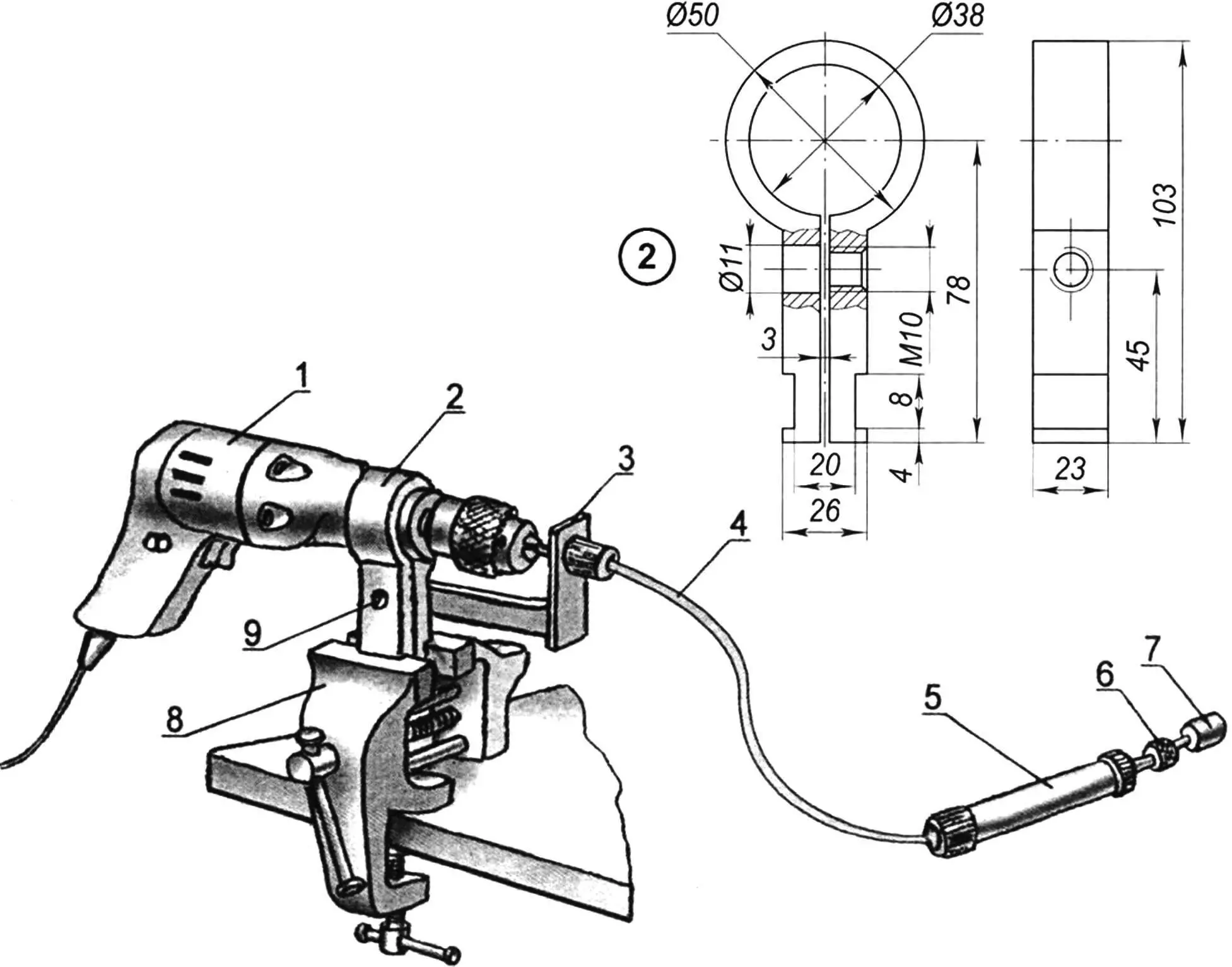
1 — electric drill; 2 — clamp; 3 — additional bracket; 4 — flexible shaft; 5 — handle; 6 — collet clamp; 7 — working tool; 8 — vise; 9 — M10 screw for tightening the clamp and fastening the bracket (with a nut). (Size “v” is selected according to the vise jaw width)
The layout of the main elements of the rotary tool is clear from Fig. 3. Torque is transmitted through the tip 9, clamped in the chuck. The end of the flexible shaft 10 protruding from the casing has a square cross-section. It is fixed in the tip as follows: insert it into a hole equal to the shaft diameter (in our case 3.2 mm) to a depth of 15–20 mm and carefully peen it over (either by riveting or by crimping the tip over a 10–15 mm length).
The adapter bushing performs several functions: it acts as a plain sliding bearing, serves to attach the shaft casing, and also presses the flexible attachment against an additional bracket that ensures alignment of the shaft with the drill axis. It is desirable to make the bushing from bronze or brass.
The working unit consists of a rigid shaft with a collet clamp, a handle with a cover, two spacer bushings, and two rolling bearings. The handle and cover can be made from any metal—bronze, steel, or duralumin. Inside the handle, a matching M16 thread is cut on one edge to secure the flexible shaft casing tip. The bearing positions are fixed by spacer bushings.
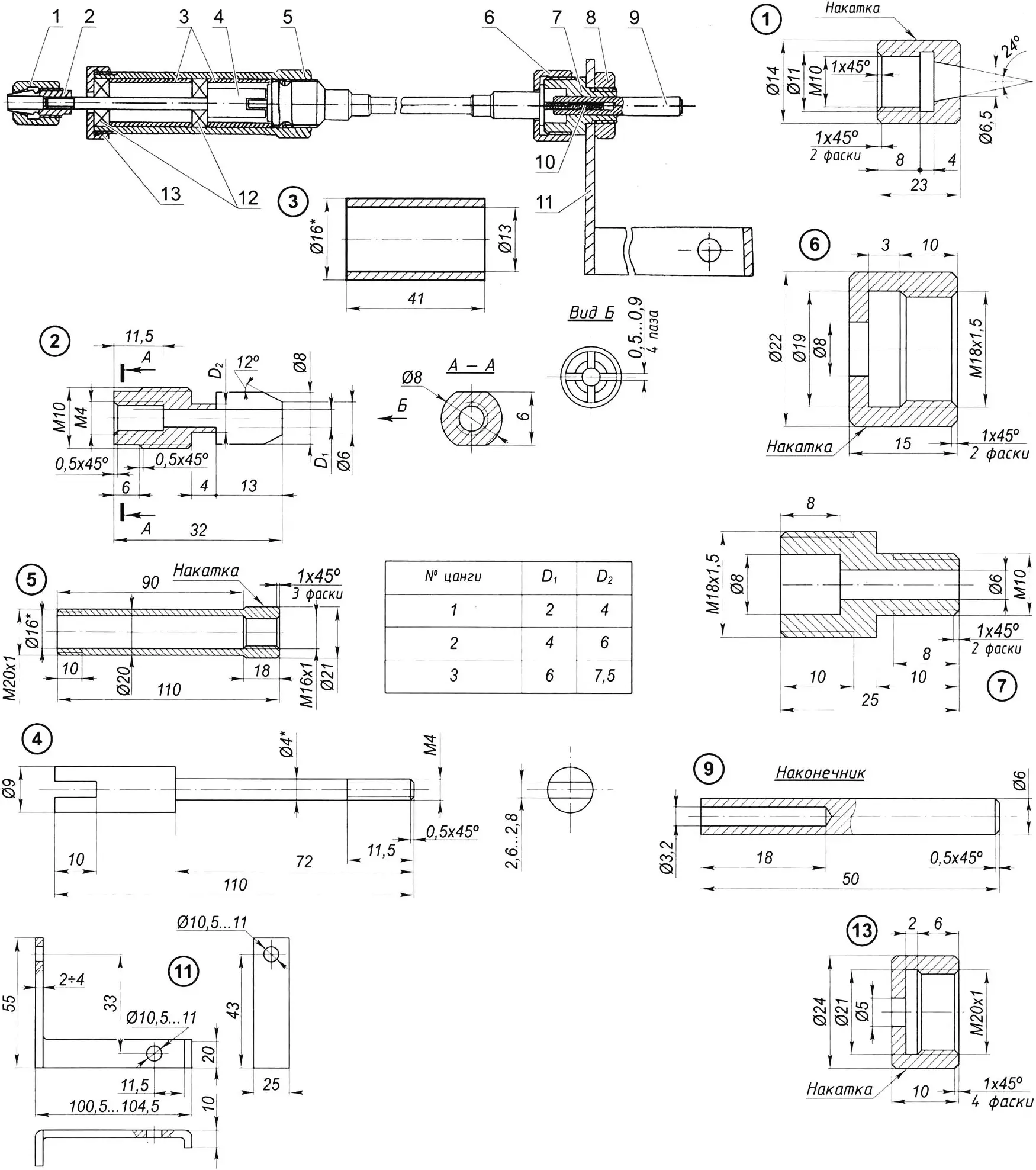
1 — collet nut; 2 — interchangeable collet; 3 — spacer bushings; 4 — rigid shaft; 5 — handle; 6 — union nut; 7 — adapter bushing; 8 — M10 nut; 9 — tip; 10 — flexible shaft; 11 — additional bracket; 12 — bearings; 13 — handle cover. (* — dimensions used for the bearings)
The rigid shaft is machined from steel and, if possible, heat-treated (hardened). The groove for connection to the flexible shaft tip and the thread for interchangeable collets on the opposite end are made before hardening.
The interchangeable collets are made for tools with shanks of three diameters: 2.4 and 6 mm. The outer dimensions of the collets are the same.
The bearings were taken from an old motor-gearbox unit. They have an outer diameter of 16 mm, an inner diameter of 4 mm, and a bearing ring thickness of 5 mm. However, instead you can use any other small rolling bearings—or even plain bearings—machining them from brass or bronze.
«Modelist-konstruktor» No. 11’2009, V. KALININ
Recommend to read
 VAZ-2118 “the guelder-rose”
A new family of cars VAZ-2118 "the guelder-rose" is only the third in 35 years of existence, the Volga automobile plant — after "penny" VAZ-2101 and "chisel" VAZ-2108/2109 — really new,...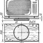 ON “PLATE” — TV
In many cases, it is convenient to mount the TV on the swivel stand. This device is easy to do on the basis of gymnastics "plate" — sports a rotating disk simulator. To turn it into a...
