 The author of this material — a pupil from the far Siberian city. When we received his letter with a description of the constructed ski-track of a snowmobile, he was 15 and he was in the tenth grade in high school. Now Eugene was older, more experienced and already a bit different, perhaps I would design the individual nodes his first ATV. But then in a letter to the editor it, recognizing myself as a newbie in the technical work, asked not to judge it strictly as a designer.
Perhaps not everyone even experienced homebrew will undertake the manufacture of caterpillar tracks, because it’s not easy. Much easier to put the bike on pneumatic low pressure — and Katie herself on the virgin snow with the wind! The more interesting result of a newbie who was not blinkered by established stereotypes and therefore are not burdened by fear of failure.
I since the childhood dreamed to build your own all terrain car. We have a place such that it is a pleasure to ride in the winter and summer, it would be only what.
Long time ago I read “modelist-Konstruktor”. Getting acquainted with the published constructions, I noticed that authors often take ready-made components and parts from other vehicles. Then I decided to use this to build my car all I have on hand. Namely, the engine of the motorcycle “IZH-Jupiter-5”, rubber band, chain, sprockets, shafts, and various steel profiles and other materials.

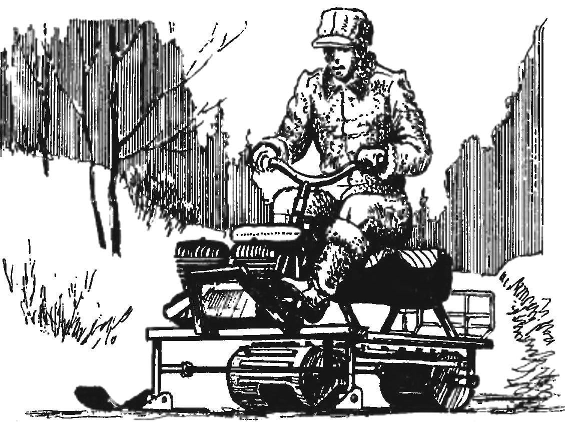
Ski-track snowmobile with an engine from a motorcycle “IZH-Unter-5” (top view trunk conventionally not shown)

The frame of the snowmobile:
1,11 — front and rear crossbar (area 50x50x5); 2 — the bump (area 50x50x5); 3 — steering beam (double angles 50x50x5); a 4.5 right and left side members (area 50x50x5); 6—middle crossbar (area 50x50x5); 7,10 — of crossmember (area 20x20x3); 8,9 — support seats (area 20x20x3); 12,14 — lining (sheet s, 4 pieces); 13 — sleeve (pipe 20×2,5,2 PCs.)

Front axle snowmobile:
1 — the frame of the snowmobile; 2 — fastening of racks (bolt M10-4 pieces); 3 — strut; 4 — fastening of the front axle (bolt M8 4 PCs); 5 — drive shaft (steel, pipe 20×3, L, 460); 6 — castle nut (steel, pipe 26×3, 2 items); 7 — cotter pin (2); 8 — the bearing housing (2); 9 — the bearing 204 (2); 10,12,15,18 — standoffs (steel, pipe 26×3); 11 — track rink (2); 13 — track sprocket (z = 8, t = 74,6); 14,16 — M6 bolts of fastening of asterisks; 17 — guiding star (z = 21, t= 15,875)

The frame of the snowmobile made from steel angles of different sections, sheet steel and pipes.
The base of the frame is a rectangle of 1500×432 mm, from a steel angle section 50x50x5 mm. the Ends of the horizontal shelves of the side members and the middle crossmember is cut down so that after welding they joined with the other pieces of rectangle flush.
Separately produced steering beam in the form of a channel, having rallied and having welded butt joint the shelves of the two sections of the area section 50x50x5 mm. At the ends of the beam top and bottom cover plates size of 100×100 mm sheet steel 3 mm thick.
Carefully set the beam horizontal drilling machine; center lining is made a through hole with a diameter of 20 mm (in the pin ski racks), drilling them at the same time with the corners.
Spaced on a rectangle and on a beam of the place of their future connections, and cut the corresponding slots. Moreover, vertical shelf rails cut at four points on the bottom exactly to the middle of their height. Four return groove width of 5 mm in the vertical shelves slotted beam, on the contrary, until the middle of the top to a subsequent welding rectangle and the beam is also connected flush.
To the front crossbar welded the bump stop from the corner section 50x50x5 mm; and the side members — cross member with U-shaped supports for the seat — area 20x20x3 mm. And supports with pre-screwed to them the seat of a motorcycle “IZH-Jupiter-5” attached in place in accordance with my height that I was comfortable.
Drilled holes in the spars bolt mounting racks front and rear axles of caterpillar tracks. Then between the steering beam and the arms are almost ready frame waril additional channel beam with located on it the standard fixing points of the engine of the motorcycle.
The most serious problems have arisen in the manufacture of the transmission and the tracks. It took a long time selection of track sprockets, and the rubber band was selected such that it was not thin and at the same time not fat. Had to “sweat” and in the calculation of the length and width of the tracks and the exact position of the holes for the sprocket teeth.
The caterpillar I made from rubber bands size 2200×300 mm and thickness 10 mm. In the ring it connects one pin to the junction of type “comb”. And stretched two special mechanisms located between the uprights front and rear axles. Each tensioner comprises a tubular spacer housing and bolt with two nuts; and the body, and bolt— with mounting bushings instead of heads.
In fact the tension of the caterpillar occurs in uniform screwing nuts on bolts of both mechanisms — the left and the right. When the required tension immediately fixed nuts with lock nuts.
Caterpillar all the way round I lined nylon threads to ensure that its territory was not stratified. Punctures in the tires by 10 mm for the needle and thread did (or rather, punched) with an awl. The work is hard, but necessary.
In the rubber band cut the holes for the sprocket teeth. Technology used the following. First drilled a hole with a diameter of 8 mm, then treated them with a knife and a file so that they become cylindrical to rectangular with the sides 14×12 mm. In the resulting hole insert mount, cut from aluminum sheet, and sewed them too capron threads.
Between the openings was attached to the rubber band lugs, which are cut out from the remnants of the same tape. Each grouser — two bolts with countersunk heads. After sea trials we had to add another bolt in the middle.
In the powertrain includes front and rear axles.
Front — leading, consists of a tubular shaft, on which is planted a crawler sprocket, track rollers and drive sprocket (from a motorcycle “IZH”). The latter is designed to transmit the stroke from the engine to the caterpillar.
Both sprockets are provided with hubs cut from pipe of suitable diameter and welded in their Central holes. On the shaft of the sprockets are fixed through bolts M6 (later it turned out that the nuts of these bolts should be sprintout, so they don’t loosen).
Rollers are chosen is ready (but you can make them yourself, here are their blueprints) and planted on the shaft without fixing. Free spaces on the shaft filled remote with bushings chosen for your place.
The shaft of the front axle rotates in two bearings 204, pressed in a simple case, attached to the posts, which, in turn, is bolted to the side members of the frame of the snowmobile.

Rear axle snowmobile:
1 — the frame of the snowmobile; 2 — fastening of racks (M10,2); 3 — strut; 4 — fastening of the rear axle (bolt M8 4 PCs); 5 — driven shaft to the track roller (steel, pipe 20×3,1,460; sheet s3); 6— castle nut (steel, pipe 26×3, 2); 7 — cotter pin (2); 8 — the bearing housing (2); 9 — the bearing 204 (2 PCs.); 10 — distance bushing (steel, pipe 26×3, 2 PCs.)
The control system of a snowmobile:
1 — steering column (steel, pipe 16×2); 2,3 — bushings (steel, pipe 20×2); 4 — motor circuit; 5 — axles (steel, rod 014); 6 — (steel, pipe 20×2); 7 — inclined tie rod (steel, pipe 16×2); 8 — frame of the snowmobile; 9 — steering arm (steel, pipe 20×2); 10,12 — ball joints; 11 — right a Pitman arm (steel, pipe 16×2); 13 — bracket lower bushing (steel, strip 20×2); 14 — loop fastener on the engine; 15,18,22 — bolts M6; 16,17 — clamp and the tip of the longitudinal steering rod; 19,20 — lugs (steel, sheet s3); 21 — sliding bearing (PTFE); 23 — the bearing shell (steel, pipe 20×2); 24 — warna stud M14; 25,33 — castellated nut M14; 26,27 — large washers (steel, sheet s3); 28 — front ski (steel, pipe 18×2); 29 — ski; 30 — left a Pitman arm (steel, pipe 16×2); 31 — ball joint; 32 — small washer; 34 — sleeve strut (steel pipe 20×3); 35 — a bolt M14

Ski:
1 — snake (steel, sheet s3); 2 — stiffener (steel, angle 30x30x3); 3,7 — brackets (steel, sheet s3); 4,6 — bushings (steel, pipe 20×2,5); 5,8 — undercuts (steel, area 170x20x2)

Design of bearing housings and stands the same at the front that at the rear axle. The only difference is that the rear rack is made without struts, as not rigidly mounted, and swivel, so you can adjust the tension of the tracks.
Rear axle consists of the same tubular shaft and drum track is set up as the front, the bearings 204 with the chassis screwed to the uprights. Details of the drum are cut from steel sheet with a thickness of 3 mm and is welded tightly to the shaft.
The management mechanism of the snowmobile is a complex spatial system composed of two skis, the longitudinal and transverse rods, stands, speakers and the actual steering of the motorcycle with all the necessary controls (grip throttle, clutch lever, etc.).
Steering column installed under the same angle as on the bike, and rotates in two bushings. The upper bushing located on the end of a broken strut that is welded to the right side member of the frame of the snowmobile, and the bottom sealed bottom that is attached to the crankcase of the engine. Driving motion from the wheel to the ski are transmitted sequentially rods, connected to each other in bits with ball joints.
In the manufacture and Assembly of the control system the most troublesome was the selection of the ratio of the length of the longitudinal thrust and right steering Pitman arm: we had to make so that any deflection of the longitudinal thrust did not touch a broken rack.
Skis are made of welded steel sheets and angles of various sections and secured to the ends of the struts with bolts. The soles of the skis are not lined with any material that reduces friction, but it should. And it turns out that the necessary rubber cords-tensioners, which would tip the ski to dig into the snow.
The gas tank and the muffler of a snowmobile — motorcycle staff; the latter is additionally drawn one bolt to the right frame spar.
The trunk is welded from pieces of steel wire and attached to the back support of the seat and to the frame rails by two clamps made of flat steel with four bolts.
My Rover could be used not only in winter, but in the snowless time. For dredge option instead of skis he needs wheels, for example, from motorized С3Д they are instead of skis. Shaft they need is the same as for the front crawler of the bridge, only longer.
Finally, to complete my Rover do not have another headlight and hook to the trailer. But that’ll come.
E. SOROKIN, Achinsk, Krasnoyarsk Krai


