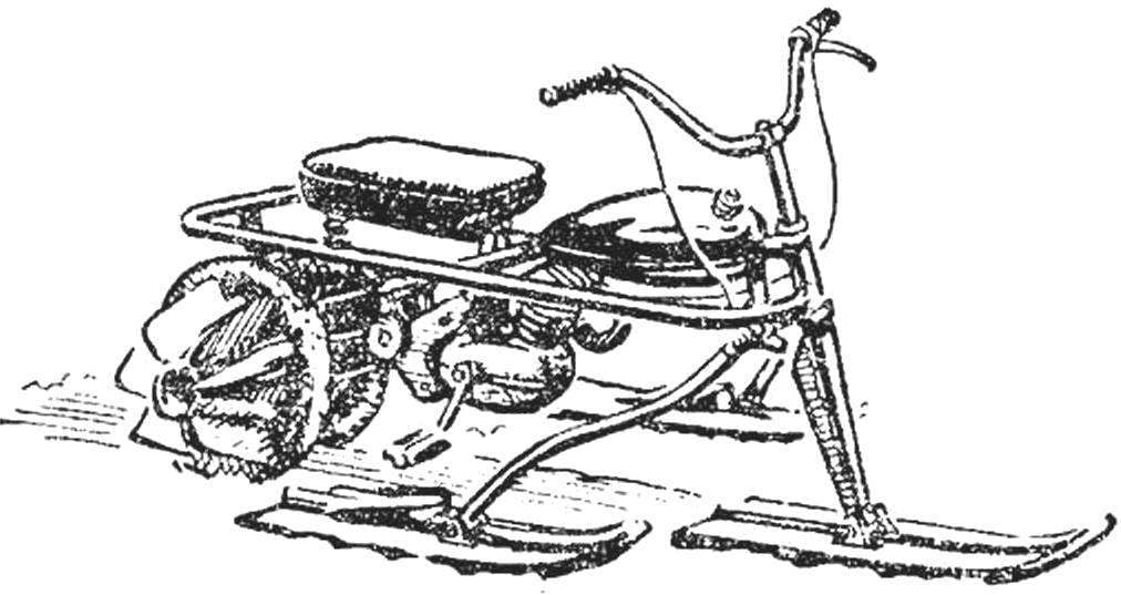
 This machine is designed and built by the young craftsmen and DHT Gorky aircraft plant them. S. Ordzhonikidze, under the guidance of the teacher L. N. Pisarevskogo. The boys set a goal to create a snowmobile with a conventional moped engine and high flotation on soft snow.
Propulsion of the snowmobile decided to do a combination, of the two coupled wheels with pneumatic tires (scooter, size 12 1/2Х21/4) having right and left shestilopastnye metal impeller that turns the propeller into a kind of paddle wheels. When traveling on dry road — Packed snow and ice — the propeller comes in contact with her only rubber tires. And in loose snow, when the tires begin to fall and slip, enter into the work of vane wheel: driving into the snow, they create tractive effort for movement of the snowmobile. Stability is provided by trehmernoi scheme of the chassis, with one managed the front of the ski and two side, on which the driver puts his feet (similar to widespread baby Sanam “Chuk and GEK”, their “motorization” we already wrote in # 1, 1978).
Side the ski is suspended on a pendulum arm and can move freely up and down, which allows the overcoming of obstacles to prevent lockups and to ensure the continued grip of the propeller with the ground.
Design “Marionka” simple welding work will require quite a bit. Frame made of steel pipes in accordance with the drawing, and assembled all units and components. The front aspect of the frame and handlebar — type Bicycle; with the Shoe, the lower end of the head tube is pivotally connected to the pylon front steering ski (bolt Ø8 mm). On the brackets welded to the lower tube of the frame, attached the pendulum arm side of the ski. There is installed a motor of sh-51 and fuel tank. The power transmission from the engine — moped chain (pitch 12,7 mm). The transmission has two circuits: the drive sprocket of the engine sprocket to the block the intermediate shaft and from the latter to the driven sprocket of the rear axle.

Fig. 1. Microsight “Morganok” diagram in three dimensions and basic dimensions:
1 — the front (steering) ski, 2 — joint of the steering ski 3 — the steering rack, 4 — pendulum side frame fork ski, 5 — frame, 6 — the rope of gas, 7 — wheel 8 — clutch lever, 9 — tank, 10 — tap of the gas tank, 11 — engine W-51-K, 12 — bolt top mount engine, 13 — seat driver, 14 — rear mount engine, 15 — block of intermediate gears, 16 — spring seat 17 — exhaust pipe, 18 — driving wheel, 19 — blade 20 — the shaft of the propeller, 21 — rear leading chain, 22 — the lower bolt of the engine 23 pedal, 24 — cable switch gear, 25 — high voltage wire, 26 — side-ski, 27 —hinge side of the ski, a 28— pendulum fork.

Fig. 2. Frame, fork, pendulum side of the ski and the driver’s seat.

Fig. 3. The propulsion Assembly and details:
1 — the hub of the driven shaft, 2 — key, 3 — spacer, 4 — tire scooter (size 12 1/2X2 1/4) in section 5 — retaining clamp rear axle, 6 — bolt clamp, 7 — sprocket driven, 8 — hub, driven sprocket, 9 — bearing housing driven shaft 10 — bearing 11 — output shaft, 12 blade.

Fig. 4. The block of intermediate gears (gearbox) Assembly and details:
1 — shaft gear unit, 2 — washer, fender, 3 — bearing housing, 4 — gear hub, 5 — sprocket, 6 — bolt fastening the gear unit.

Fig. 5. Preparing the blade for welding.

Fig. 6. Skis and steering rack.
Intermediate block sprocket located behind the engine. It consists of a rack attached to the pipe frame on which two radial bearings No. 202 planted the shaft with the sprockets (one with 18 and one with 24 teeth). For the selection of the most advantageous gear ratios while riding in the snow of different densities, that is, to get the most traction, sprocket, intermediate drive train unit is made easily removable. For example, if you intend to drive but the deep snow, it is on the intermediate shaft to put these stars: medium — with 26 teeth, the console — with 28 teeth.
The rear unit consists of the same strut bearing No. 202 in which the shaft of the propeller-driven sprocket having 20 teeth. Rear axle shaft has a tapered neck on them (with dowels) are wheels with blades. Blades pre-welded to the cone bushings and the outer wheels. Sleeve to tighten on the nuts and cones counter round soft wire or cotter pins — if you have castellated nuts (see Fig. 2, Assembly drawing rear axle).
I. USENALIEV


