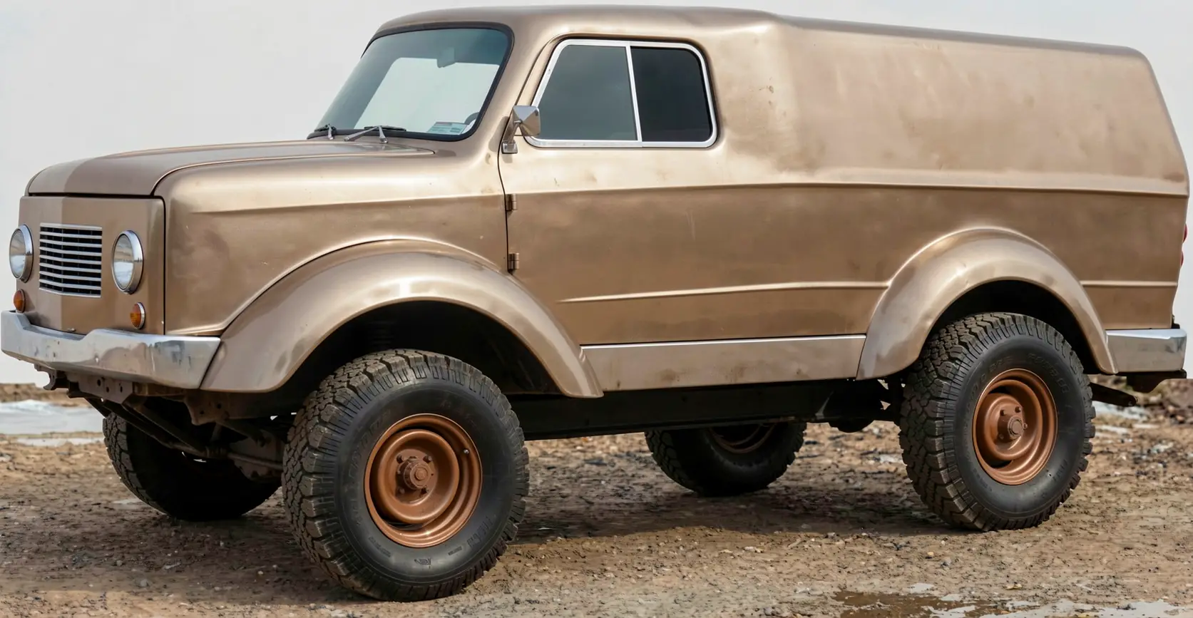
The author of the article and the creator of the all-terrain vehicle discussed here is Boris Nikolayevich Ryzhov — a long-time acquaintance of our magazine’s readers. Photographs of the machines he built (a tracked and a six-wheeled all-terrain vehicle) were published in the magazine as early as 1990 (No. 7).
But the desire to create and to build a more advanced high-mobility vehicle has not cooled since then. A professional aviation mechanic and tireless amateur designer, after retiring he continued to build all-terrain vehicles. Why them? Because for now (and, apparently, for a long time to come) you can reach most places in the Siberian backcountry where Boris Nikolayevich lives only on such machines.
And if you are also a fisherman or hunter, such a machine is simply indispensable.
Over the past few years he has built three more all-terrain vehicles (materials on two previous ones were published in No. 1’2000 and No. 12’2003).
All the machines have one thing in common: identical propulsion units — pneumatic tires (the author considers them the most universal propulsion — for any season). Otherwise, each machine has its own features, but the latest is perhaps the strongest and most advanced of them.
The story of my next pneumatic-tire all-terrain vehicle was started back in No. 12 for 2003. At the very end of that publication I gave a brief technical specification of the new design I planned to build. Now that the machine has been assembled, tuned, and tested, it is time to tell readers about it on the pages of the magazine.
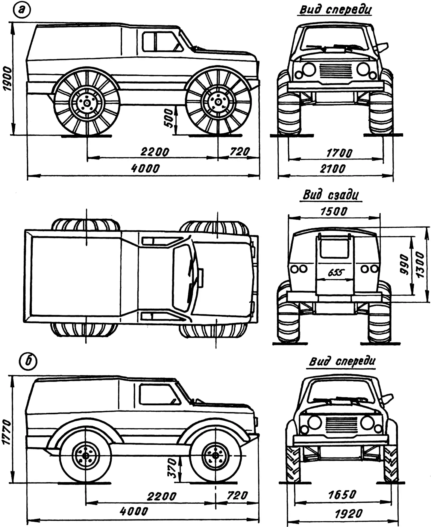
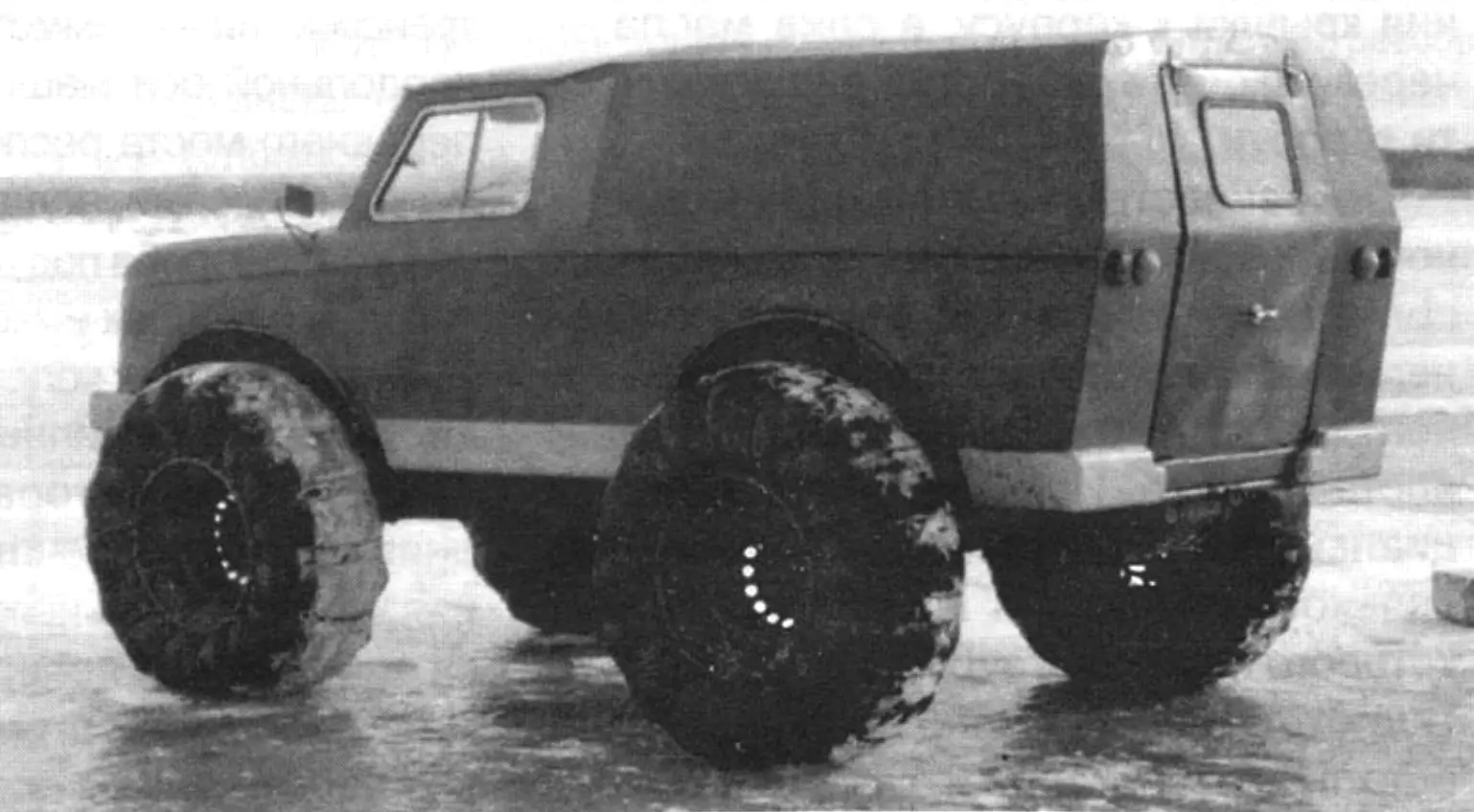
a) on homemade pneumatic tires (all-season version); b) on wheels from a UAZ-469 automobile (summer version)
As in the preliminary estimates, I made the machine with all four driving wheels — in short, a full-fledged off-road vehicle.
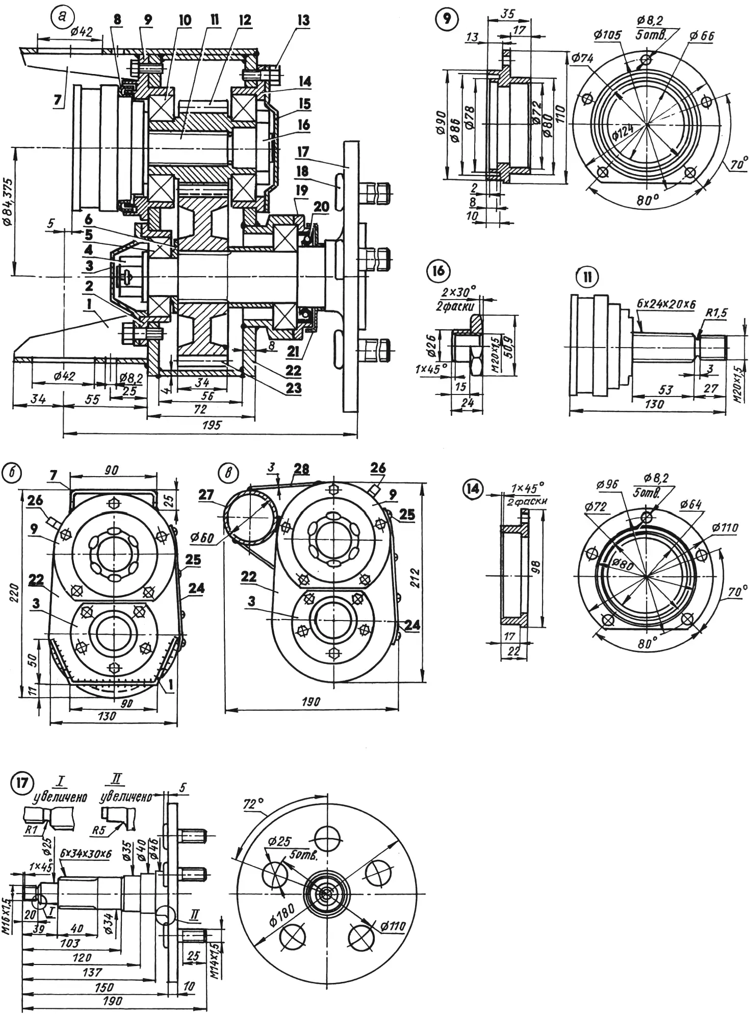
For this I had to build a transmission similar at once to the power trains of the Niva and the LuAZ. Similarity to the first is expressed in a lockable two-speed transfer case, two final drives (to the front and rear wheels), and torque transfer from the final drive to the wheels by shafts with CV joints. Similarity to the LuAZ shows up in the presence in the same transmission of propeller shafts and wheel reducers with a gear ratio i = 2 — for an all-terrain vehicle on large-diameter pneumatic tires these mechanisms are also necessary. Cylindrical gears with module 3.75 (z1 = 15, z2 = 30) were ordered from specialists; the rest of the reducer parts, including the housings, are homemade.
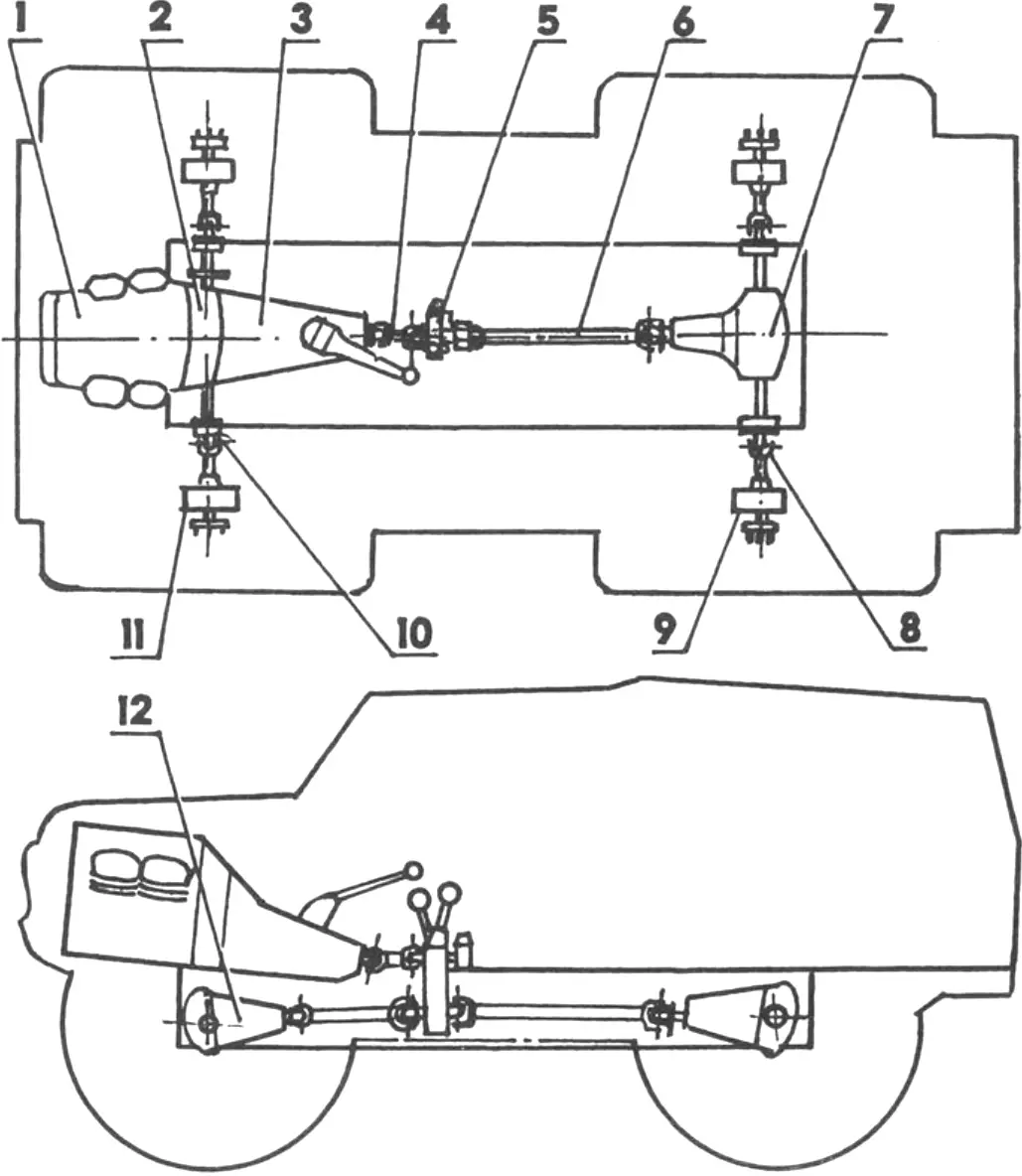
1 — engine (from a Zaporozhets automobile, 40 hp); 2 — adapter housing with clutch from a Zhiguli automobile; 3 — gearbox (from a Zhiguli automobile); 4 — short propeller shaft; 5 — transfer case; 6 — rear axle propeller shaft; 7 — rear wheel drive reducer; 8 — rear wheel drive mechanism (2 pcs.); 9 — rear wheel reducer (2 pcs.); 10 — front wheel drive mechanism (2 pcs.); 11 — front wheel reducer (2 pcs.); 12 — front wheel drive reducer
I made the body two-volume (engine compartment and cab combined with the luggage compartment) — in my opinion, this layout is the most rational. For the engine compartment and cab I adapted the front half of the body of a Zaporozhets automobile (ZAZ-968). The luggage compartment is combined: the lower part of the sides is metal (welded from doors of various old cars); the upper part of the sides and the ceiling (or rather the roof, but I have disliked that word since the reforms began) are plywood, covered outside and inside with leatherette. The cavities in the lower part of the cab and body sides were filled with construction foam — for buoyancy and thermal insulation. The latter also matters: there is no standalone heater in the cabin yet, and warm air enters only from the engine compartment through a hatch in the front wall. The rear wall is entirely metal. It has a metal door 990 mm high and 655 mm wide — only one for the entire vehicle. Someone may find such a body design unusual or even strange (after all, some cars — even subcompacts — have up to five doors), but I believe it is justified for an all-terrain vehicle. Increased body rigidity when constantly traveling over rough terrain is never excessive, as is watertightness — trips onto ice-covered rivers and bodies of water during winter fishing are quite frequent.
The door, as on most station wagon or hatchback bodies, lifts upward and is held by two springs (from the front fork of a Minsk motorcycle). The door has a small window, and the door opening is edged with a sealing gasket. There are only two seats in the cabin up front: driver and passenger. Behind the seats is free space measuring 1700×1350 mm. Two people can even lie down comfortably here.
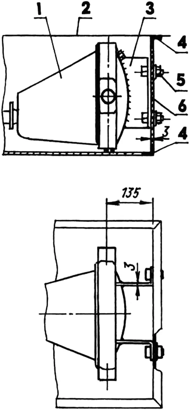
1 — housing; 2 — body floor; 3 — angle bracket; 4 — transverse box beam (35×35 angle); 5 — M10 bolt with nut and spring washer (4 pcs.); 6 — box cladding (St3, sheet s3)
The windshield is from a Zaporozhets automobile. The side windows have sliding vent windows. In time I plan to make a roof hatch — for better summer ventilation and as an emergency exit.
The all-terrain vehicle frame is rather unusual: its basis is a box of simple rectangular shape with ribs made of 35×35 mm steel angles. The upper box ribs are welded to the body floor. The box protects transmission units from dirt and accidental damage when driving off-road and provides additional displacement to keep the machine afloat — sometimes you have to travel on weak ice. Almost all transmission assemblies and units are located in the box: gearbox, transfer case, propeller shafts, final drive housings of both axles. In the front and rear axle areas the box walls and bottom are made of 3-mm steel sheet, and between them — of fiberglass (several layers of glass cloth impregnated with epoxy resin). Access is through hatches in the floor. Angle brackets with 45×45 mm flanges are bolted to the vertical side walls of the box at the suspension arm mounting points on the frame. Final drive housings are attached to the end walls of the box (front and rear) through welded angle brackets.
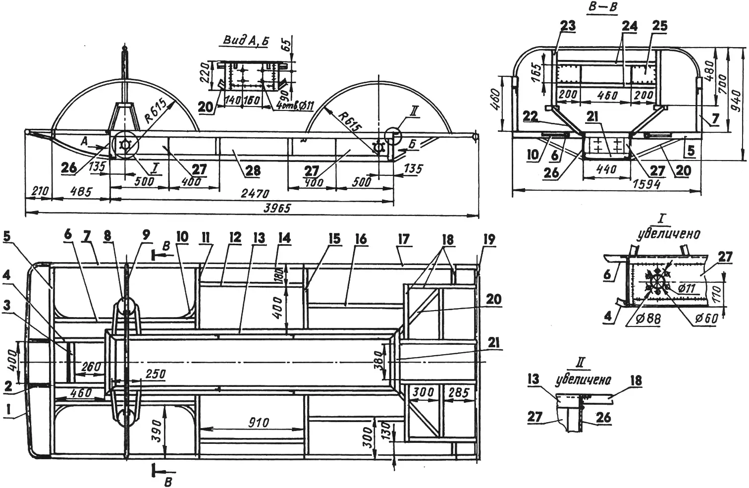
1 — front fairing (Ø16 tube); 2 — spacer (Ø16 tube, 2 pcs.); 3 — cross member (50×25 tube); 4 — sub-steering side member (50×25 tube, 2 pcs.); 5 — front cross member (50×25 tube); 6 — front longitudinal beam (25×25 tube, 2 pcs.); 7 — front wheel arch arc (25×25 angle, 2 pcs.); 8 — spring seat cup (2 pcs.); 9 — tie rod (Ø16 tube); 10 — front wheel arch brace (25×25 angle, 4 pcs.); 11 — front transverse beam (25×25 tube, 2 pcs.); 12 — middle longitudinal beam (25×25 tube, 2 pcs.); 13 — box side member (35×35 angle, 4 pcs.); 14 — sill (25×25 angle, 2 pcs.); 15 — rear transverse beam (50×25 tube, 2 pcs.); 16 — rear longitudinal beam (25×25 tube, 2 pcs.); 17 — rear wheel arch arc (25×25 angle, 2 pcs.); 18 — rear overhang frame parts (25×25 tube, 2 pcs.); 19 — rear cross member (Ø35 tube); 20 — rear overhang frame brace (25×25 tube, 2 pcs.); 21 — box transverse beam (35×35 angle, 4 pcs.); 22 — spring seat cup console (25×25 tube, 4 pcs.); 23 — spring cup support strut (25×25 tube, 2 pcs.); 24 — strut cross members (25×25 tube); 25 — engine bracket mounting panel (St3, sheet s3, 2 pcs.); 26 — box strut (35×35 angle, 4 pcs.); 27 — metal box cladding (St3, sheet s3); 28 — fiberglass box cladding (glass cloth, epoxy adhesive, 3 layers)
A Zaporozhets engine rated at 40 hp is mounted above the frame in the engine compartment at the front. Relative to how it is installed in the base car, the engine is now rotated 180°. A Zhiguli gearbox with clutch is mated to it. For this the clutch housing had to be replaced with a homemade adapter housing, one side matching the engine mounting holes and the other — the gearbox. The transfer case is homemade. Its housing is welded from steel sheets 4 to 6 mm thick. Oil is filled through one of the upper bolt holes for attaching the cover to the housing, and drained through a similar hole in the lower part of the case.
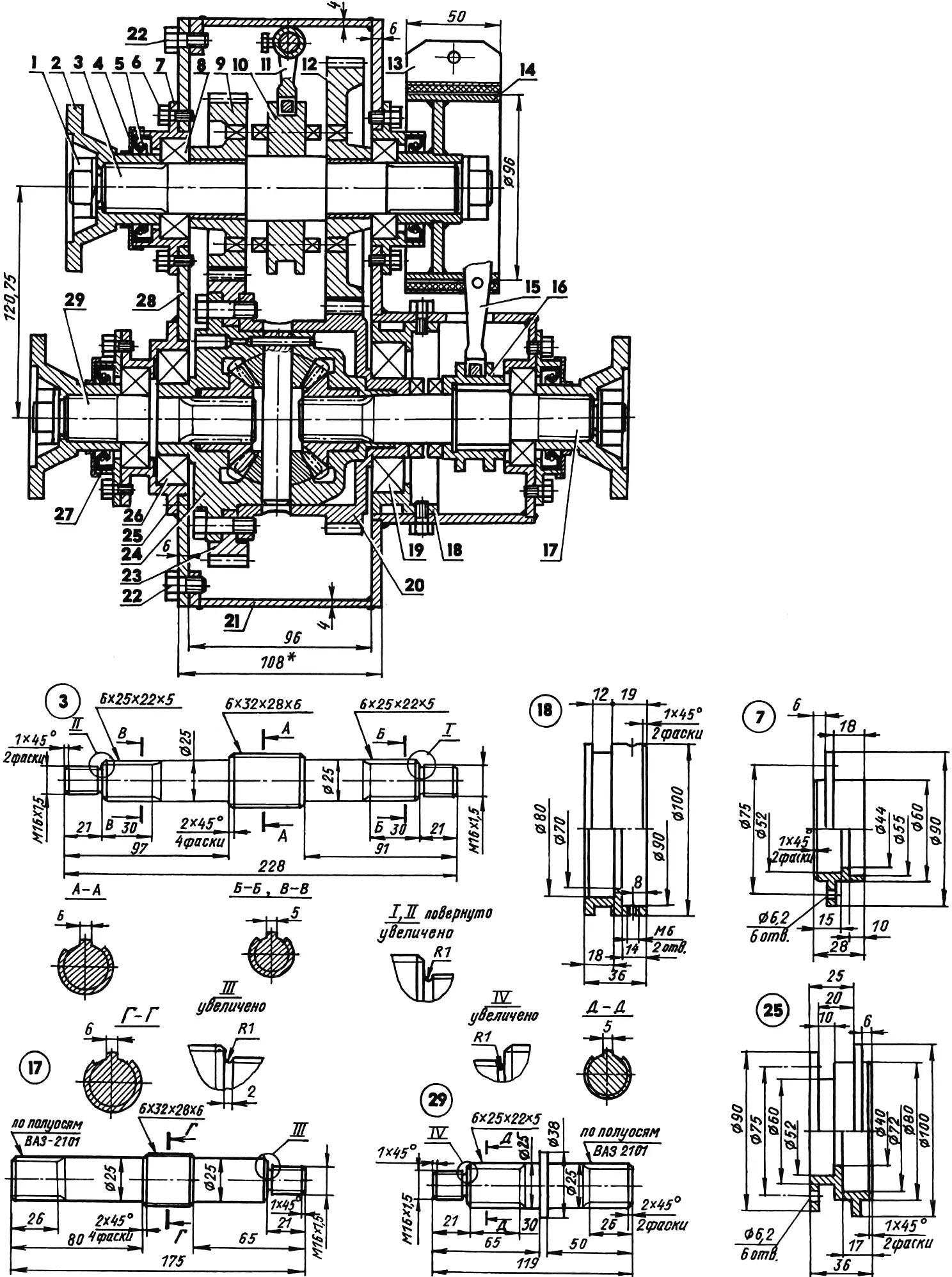
1 — M16x1.5 nut with spring washer (4 pcs.); 2 — short propeller shaft connection flange; 3 — primary shaft; 4 — boot (3 pcs.); 5 — oil seal (4 pcs.); 6 — M6 screw (24 pcs.); 7 — bearing housing (2 pcs.); 8 — 205 bearing (4 pcs.); 9 — primary shaft small gear (z = 26); 10 — gearshift clutch; 11 — gearshift mechanism; 12 — primary shaft toothed wheel (z = 36); 13 — hand brake drive; 14 — hand brake; 15 — differential lock mechanism; 16 — differential lock face clutch; 17 — front transfer shaft; 18 — bearing housing; 19 — 208 bearing; 20 — cup gear (z = 33); 21 — transfer case housing (steel sheet, s4…6); 22 — M8 screw for attaching cover to housing (6 pcs.); 23 — toothed wheel rim (z = 43); 24 — differential (from VAZ-2101 automobile, assembled); 25 — bearing housing; 26 — 207 bearing; 27 — bearing housing cover (2 pcs.); 28 — housing cover (steel sheet s6); 29 — rear transfer shaft
A feature of the transfer case design is that it uses a complete rear axle differential from a Zhiguli automobile. Only the outer surface of its housing is turned. A special cup gear (taken from agricultural machinery) is fitted onto the housing; teeth with module 3.5 are cut on its circular boss. All other transfer case gears and toothed wheels were ordered for this module. The cup end (it has a flange) abuts the rim of the toothed wheel fitted on the differential housing. All mentioned parts are joined into one unit with M10 screws (longer than standard).
1 — front suspension lower arm bracket (St3, sheet s3); 2 — bearing housing; 3 — bearing housing cover; 4 — M16x1.5 nut with washer; 5 — 205 bearing; 6 — spacing thrust washer; 7 — front suspension upper arm bracket (St3, sheet s3); 8 — boot (St3); 9 — bearing housing with labyrinth grooves; 10 — 207 bearing (3 pcs.); 11 — splined shaft (from VAZ-2108 CV joint, modified); 12 — drive gear (m = 3.75, z = 15); 13 — M6 screw (15 pcs.); 14 — bearing housing; 15 — cover; 16 — special nut; 17 — wheel mounting flange; 18 — threaded pin; 19 — bearing housing cover; 20 — oil seal; 21 — boot; 22 — wheel reducer housing (St3); 23 — driven gear (wheel, m = 3.75; z = 30); 24 — reducer housing cover (St3, sheet s3); 25 — M4 screw (8 pcs.); 26 — breather (from agricultural machinery); 27 — rear wheel suspension longitudinal arm (Ø60×3 tube); 28 — arm mounting gusset (St3, sheet s3, 2 pcs.)
The engine and all transmission units are arranged symmetrically about the longitudinal axis of the machine. Even the front axle reducer is located midway between the wheels, under the engine.
Behind the box, under the body floor, a 35-liter fuel tank is mounted.
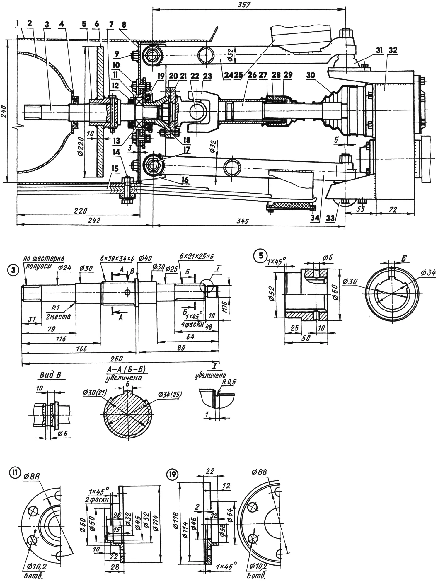
1 — body floor (from ZAZ-968 automobile); 2 — final drive housing (rear axle reducer parts not shown, from VAZ-2101 automobile); 3 — half-shaft (from VAZ-2101 automobile); 4 — oil seal; 5 — splined bushing; 6 — brake disc; 7 — lock pin with washer and cotter pin; 8 — box-frame (steel, sheet s3); 9 — M10 bolt for arm bracket mounting (2 sets); 10 — M8 bolt with square washer for bearing housing mounting (4 pcs.); 11 — bearing housing; 12 — oil seal; 13 — 205 bearing; 14 — M10 bolt with plain and spring washers; 15 — leaf spring (3 leaves, from Moskvich-412); 16 — arm mounting bracket (45×45 steel angle); 17 — M16 bolt with nut, silent block and two washers (2 sets); 18 — M8 bolt connecting flanges with spring washer (4 sets); 19 — oil seal housing with boot; 20 — splined flange (from agricultural machinery); 21 — flange with universal joint yoke (from agricultural machinery); 22 — universal joint cross (from agricultural machinery); 23 — universal joint yoke with splined bushing (from agricultural machinery); 24 — upper arm (Ø32 steel tube); 25 — spring seat cup; 26 — CV joint splined shaft; 27 — rubber boot; 28 — limit nut; 29 — shock absorber (rubber washer); 30 — CV joint rubber boot (from Niva automobile); 31 — upper ball joint (from VAZ-2101 automobile); 32 — wheel reducer; 33 — lower ball joint (from VAZ-2101 automobile); 34 — lower arm (Ø32 steel tube)
All wheel drives are identical. The suspensions are also of the same type — coil-sprung with shock absorbers; only the front is on transverse arms and the rear on longitudinal ones. The front suspension is further reinforced with a transverse three-leaf spring from a Moskvich, and the wheels are made steerable.
The all-terrain vehicle wheels are interchangeable. In summer I fit UAZ wheels, and in other seasons — homemade pneumatic tires — the same as the front ones on the previous all-terrain vehicle model. A description and drawings of the pneumatic tires were published in No. 1’2000 of Modelist-Konstruktor magazine. In the UAZ wheels, so they would fit Moskvich flanges, I cut out the middle part of the disc together with the holes and welded another homemade one in its place with suitable holes.
The fenders over the wheel arches are removable: when changing to pneumatic tires I remove the fenders as well.
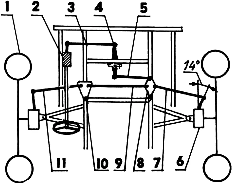
1 — front steering wheel (2 pcs.); 2 — steering mechanism (steering wheel, shaft, worm reducer, pitman arm); 3 — first intermediate link; 4 — two-arm pendulum lever; 5 — second intermediate link; 6 — wheel reducer with lever (2 pcs.); 7 — right link; 8 — right joint; 9 — middle link; 10 — left joint; 11 — left link
When changing propulsion units, some overall dimensions change slightly: thus, the vehicle height on wheels is 1770 mm, on pneumatic tires — 1900 mm, and width, respectively, 1920 and 2100 mm. Ground clearance changes similarly from 370 mm to 500 mm.
All steering mechanisms, units, and parts are from a Zhiguli automobile, and only the steering wheel is from a Zaporozhets.
The speeds of the all-terrain vehicle, and along with them the speedometer readings with different propulsion units at the same engine speed in the same gear, differ. The speedometer is calibrated for UAZ wheel revolutions, and when driving on pneumatic tires these readings must be corrected — multiplied by a factor of 1.5.
Maximum speed on UAZ wheels in low transfer range is 40 km/h, in high range — 60 km/h. On pneumatic tires I do not engage high range — even in low range the speed reaches 60 km/h.
Modelist-Konstruktor No. 5’2004, B. RYZHOV
Recommend to read
 TO FIX WITHOUT MOUNTING
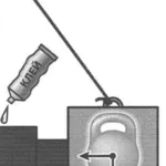
So will be able to do if you need to glue some detail to a vertical surface. There is a simple way really allows you to do in this case bezdolnogo temporary fasteners will be replaced by... THE FIRSTBORN OPALEWSKI FIVE-YEAR PLAN
Family compact MPV OPEL MERIVA. One of the most promising directions in the production program of the German company Adam Opel AG will be in a future edition of one-volume cars. And it's...
