Cylinders, pistons Assembly and the carburetor is from a chainsaw “Ural-2 Electron”. Since the stroke of the “Breeze” is not the same as those of the chainsaw 2 mm, it is necessary from the surface of the crankcase at the junction with the cylinder to remove 1.5 mm and bring the interface parts on the lapping plate. So the pistons do not overlap the vent window, their bottoms podrachivala Windows in the skirt, happening.
The locking pins of the upper piston rings should be moved 5 mm in a clockwise direction when viewed from above. Piston pin Ø 13,8 mm, you can use a chainsaw or take your finger Ø 14 mm from a motorcycle “IZH-Jupiter”, expanding the holes in the lugs to size. Bronze bushings in the upper head of the connecting rod is replaced by roller bearings for reliability, and seats of the connecting rod grinded to the appropriate size. At the bottom of the heads, crankcase cover and crankshaft Central support — rollers 0 to 2.5 mm and a length of 12.6 mm, and the ends of the shaft — bearings № 204.
The layout of the engine:
1 — Central bearing crankshaft, 2 — needle bearings (roller length 12.6 mm, Ø 2.5 mm), 3 — cover of a crankcase of the engine “Breeze-12”, 4, 5 — cylinder and piston chainsaw “Ural-2 Electron” 6 — piston pin 7 — the needle bearing (roller length 15 mm, Ø 2 mm), 8 — rod engine “Breeze-12”, 9 — Piston ring chainsaw, 10 — stopper, 11 — Carter motor “Breeze-12”, 12 — bearing.
To install cylinders in a row they should be cut 10 mm from the intake Windows are closed dural plates fastened with M3 screws with countersunk heads with the sealing epoxy resin. To the cylinder sleeves are not rested on the Central support and the crankcase cover, the last was cut down to a depth of 4 mm In the cover plate, in addition, two holes drilled for lubrication of roller bearing.
With vertical cylinders is used bespopovtsy diaphragm carb (PCF-100U chainsaw). The horizontal arrangement of the cylinder — carburetor from the “Breeze-12” or other, with a diffuser of suitable diameter. The fuel flows by gravity.
To simplify the engine and decrease the weight applied to the battery ignition. A battery of four accumulators SPD-12 weighs 1 kg; its capacity is sufficient for eight hours of work. The contacts of the interrupters from a two-cylinder motorcycle “Java” or “Ij”. High voltage transformers TLM (ignition coil) — from unified maggino MN-1 used in boat motors “hi-22” and “Whirlwind”. Spark plugs — SI 12РТ or PAL-14-7. Spark advance is 2.8—3.5 mm Btdc. To start the engine used lightweight pulley, coaxial with the air screw.
The necessary compression ratio in the combustion chamber is selected by the thickness of the gasket between the crankcase and the cylinder.
The power boost can be increased to 14-15 HP Recommendations for improving the capacity of the “Breeze-12” can be found in the magazine “Boats and yachts” (No. 6, 1972, and No. 6, 1973).
Hope the engine is “Cyclone” will be interesting not only for gliders, but also other enthusiasts of technical creativity.
If you intend it for a glider, then don’t miss sight of the fact that the aircraft itself must comply with the “Provisional technical requirements for gliders” (HTTD-80), available in all territorial and regional committees of DOSAAF of the country.
When installing the engine everyone will be faced with several conflicting requirements: the center of gravity of the system of “pilot — glider” doesn’t change its position; operating the engine as not to cause a dive or carerully time; rotating the screw to stay as far away from the pilot.
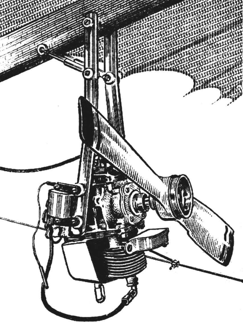
We chose the structure with a rear engine, but has not applied for pushing and pulling the screw to better cool the cylinders. Serves the same purpose and cowl from thin aluminum sheet. This design resulted in a set screw Ø 700 mm to 30 kgf thrust with a slight cabriolet moment.
Front suspension engine balancing machine at the speed the greatest aerodynamic quality (in which the force on the handle of the trapezoid is missing). Then on the keel hung the engine.
Refinement of the crankcase cover.
A refinement of the piston.
Test flights have not started the motor to determine the speed the most aerodynamic qualities and balancing apparatus transfer the suspension point of the pilot in the small range. It is necessary to ensure that the new trim speed was slightly greater than without an engine. To start better with the hills; well, if the assistant will support the keel tube. Fly right with smooth head wind, the speed of which does not exceed 6 m/s (calm take-off difficult and unsafe). During the takeoff run and the engine should work with small number of revolutions. Upon reaching the balancing speed, the revs increase, making sure that the air speed of the glider have not changed. The flights should be discontinued upon appearance of a dive or a big pitching moments. Their presence indicates improper installation of the engine. Conducting test flights and adjusting the mounting angle of the motor relative to the keel, to achieve a slight pitching moment that does not prevent the long flight. Before planting, you must lower the revs, ignition off and land in the usual way, remembering, however, that the landing speed must be higher — because the specific load on the wing more.
Special attention to safety. The hang glider before installing the engine it is necessary to increase the diameter of keel tube. Also need to strengthen cross tube — around the Central node. All threaded connections must be securely scontrini. Prior to each flight is necessary to carefully inspect the glider and propeller installation. The propeller shall be fenced, and the engine — ignition switch and also emergency device that stops the motor when the pilot releases the handle of a trapezoid. Every time you start be very careful to make sure that the assistant was not near a screw or in the plane of rotation.
Yuri MAZUROV, I. POLUSHKIN, V. RUSAKOV, Omsk
Recommend to read YOU NEED A CHAIR! CHOOSE! In the mail "Club house masters" are sometimes most controversial letter. Some readers, for example, write that they expect from the magazine, in particular the sections of "All for... GRANDNEPHEW Compact car Polski FIAT 126 p. The present publication, we complete the story of the glorious cohort of Italian runabout, initiated by FIAT-500 Nuova, designed by the famous avtodizayner... 
 Did not have time to be approved and become a massive new and exciting sport of hang gliding enthusiasts as it took to lay another area in the technical work associated with designing balancing aircraft, — the construction of trikes.