In Arkhangelsk there are several very distinctive “schools” oriented towards the creation of vehicles of certain types.
The closest to industrial design, for reviews Arkhangelsk homebrew, pneumatic-tired machines are a senior researcher Senip V. Ilyin, V. Bazhukova and “shestiklassnik”, Vidyakina.
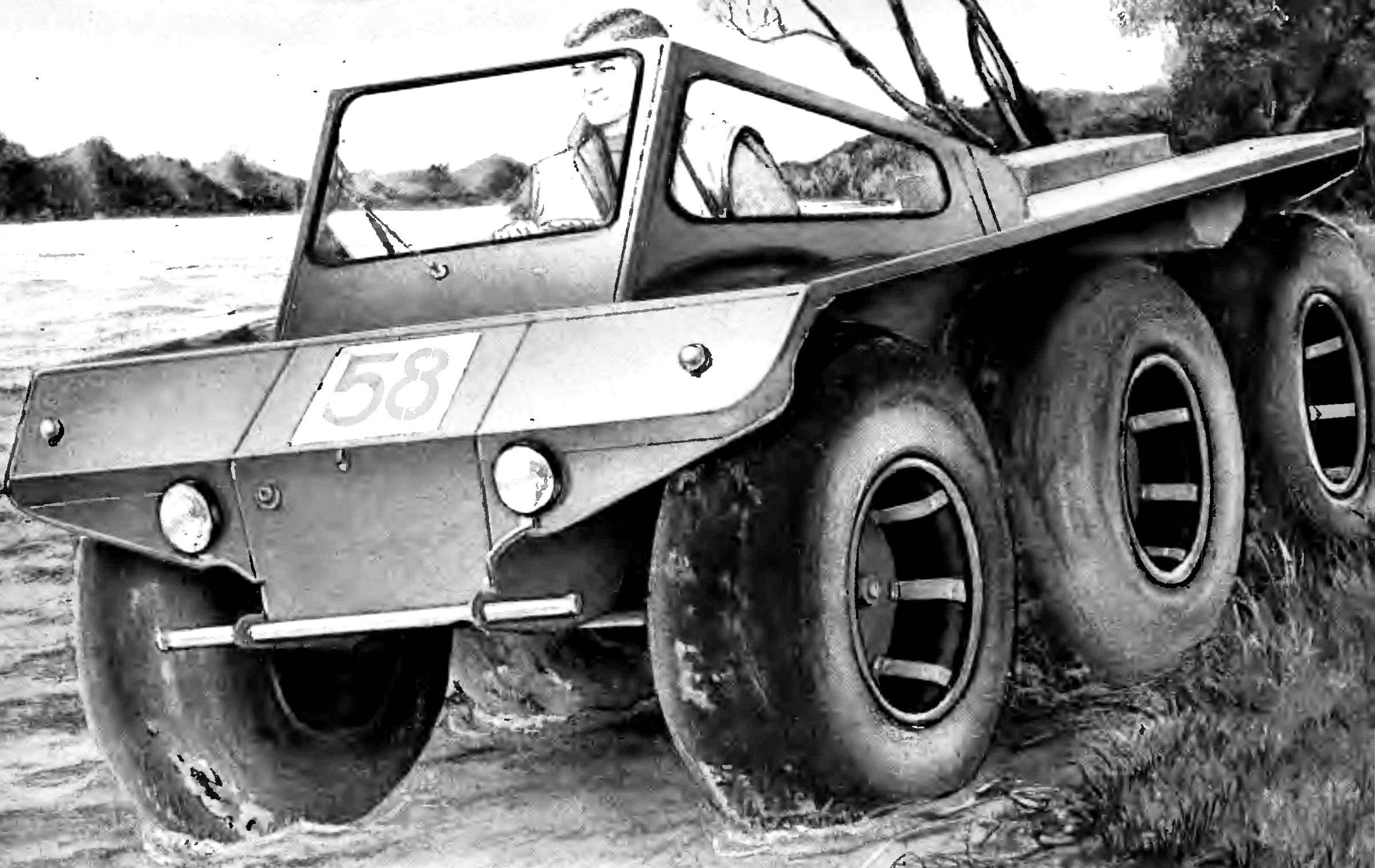
With pneumatic G. Vidyakina, won a prize at the competition, I want to introduce to the readers. Gennady A. Vidyakin by profession a mechanical engineer. By the nature of the work he was long connected with motor vehicles, manufacturing a variety of transport equipment is engaged in more than a decade. Submitted for the contest Rover — the third on his account, and, perhaps, the most perfect. So, the Arkhangelsk regional Council of VOIR recommended that the Rover G. A. Vidyakina for demonstration at VDNKH in Moscow. The layout of the suspension fairly worked out and designed for maximum use of standard components. G. Vidyakin were in the same and a good designer: it “shestiklassnik” has an attractive appearance, its equipment takes into account the requirements of the SAI, applicable to vehicles. However, on such vehicles not subject to the requirements of the SAI, applicable to a self-made cars, so they are not recorded. However, they are allowed to operate by setting out similar machines from city-specific routes and time.
The basis of the vehicle G. Vidyakina is open-topped box-shaped body shape. Vertical boards — plywood with a thickness of 7 mm, at the upper edge of the sides attached wings, forming a single plane in front made a small bevel. In terms of housing is rectangular in shape with a slightly tapered front part. The body is divided by vertical cross partitions; in front of the trunk, then in the expanding part of the cabin with a steering wheel and driver’s seat behind him on the sides of the two boxes that serve as seats for passengers. Next compartment — transmission compartment. By the way, the drivetrain is covered with a horizontal cover, are at the same level with the seat. And the last compartment — power, closed the horizontal lid, slightly raised above the seats in which is mounted the engine. On the lid there is an additional box-shaped casing under the engine. Covers of boxes, transmission and engine hood recline on hinges, for easy access to the units.
Fig. 1. Three-axle all-terrain vehicle on low pressure tires design G. Vidyakina:
1 — support of front axle, 2 — bumper, 3 — steering gear, 4 — the balance wheel of the rear wheels, 5 — chain transmission to the rear wheel, 6 — fuel tank 7 — step, 8 — wheel disc, 9 — wheel hub, 10 — front axle, 11 camera, 12 — valve, 13 — the outer rim 14 on the wheel shaft of the rear axle.
Fig. 2. The steering gear and support the front axle:
1 — support of front axle, 2 — tie rod end joint, 3 — pinion steering, 4 — body, 5 — hinge, 6 — steering column 7 — the tie rod.
Wings, partitions, covers and plywood, coupled with the body dural corners, half of duralumin sheet, from the bottom to the rigidity of riveted duralumin angles. In front of the body under the partition boot made with a small cross in a niche under the front axle. In the rear of the body under boxes-seats and on to the engine compartment, on both sides, both longitudinal niche for balance weights rear wheels. By the way, the rear wheels are as close to each other, front related several forward — from this distance depends on the turning radius of the vehicle.
Over the wings in front of the body inclined installed windshield and two side Windows. Under the wings of each rear wheel with two sides mounted fuel tank, the cross section of which has the form of a narrowing down of the trapezoid. Over all the wheels in the horizontal parts of the wings are made of rectangular cutouts closed by a rubberized fabric: when you hit a barrier that allows the wheels to rise above the level of the wings and not inhibited about them.
The engine and transmission units are mounted on a frame constituting a single whole with the body. It consists of four longerons of steel 40X40 mm angles and cross members of steel pipes of square section. Outside on the sides there are small brackets from the corner 40X40 mm for fixing the supports of beams of the rear wheels. Wherever possible corners of the shelf longitudinal spars trimmed to reduce the weight and nasverlennye holes.
Fig. 3. The device, transmission:
1 — chain, 2 — the frame of the balancer, 3 — axle, 4 — pole balancer, 5 — bracket, 6 — side, 7 — gear, 8 — elastic coupling, 9 — drum, 10 — sprocket chain transmission differential lock, 11 — brake lever, 12 — intermediate shaft 13 — shaft gears.
Fig. 4. The body of the Rover:
1 — trunk 2 — windscreen 3 — driver seat, 4 — box, 5 — place for passengers and Luggage, 6 — window, sometimes there are small rubberized cloth, 7 — engine cover, 8 — mud flaps, 9 — Board, 10 — side power rails of the frame of the engine and transmission, 11 — recess of the rocker rear wheels, 12 — niche of the front axle.
Fig. 5. Frame under the engine and transmission:
1 — medium spars (area 40X40MM), 2 — cross (square tube 40X40 mm), 3 — side rails (area 40X40MM), 4 — cross member (area 30X30 mm), 5 — support bracket of balancer (area 40X40MM).
The engine of the motorized FDD is mounted in the rear on intermediate supports which, in turn, four damping rubber strip from the engine of “Moskvich” attached to the spars. On intermediate supports also install the cross member with the intermediate sprocket connected to the vertical chain to the output sprocket of the engine. The intermediate shaft sprocket through the intermediate roller with the elastic couplings (elastic element is a disc from a flat drive belt 10 mm thick) connected with a corner bevel gear mounted on the crossmember. The output shaft of the reducer mounted sprocket, linked chain transmission with an input shaft main gear (motorized), mounted on two cross members. Output shafts of the main transmission through an elastic coupling (from the same timing belt) is connected with the intermediate shafts with the sprockets, transmitting via a chain drive rotation of the wheel. Output shafts of the main transmission, intermediate shafts and axle beams are aligned, as shown in figure 3. It can be seen that the axles are fixed in the supports with bearings, the axle bearings are pressed on the same intermediate shafts. The inner axle is hollow, it passes through the intermediate shaft. On the inner ends of the intermediate shafts mounted brake drums from the wheels of the scooter Tulitsa which have ring gears; chain transmission and are connected to the rollers of the differential lock. The latter is a sliding splined sleeve that connects the rollers. The axis of all transmission mechanisms are located substantially in one plane. The tension of the chain transmission: transmission — using the gasket, transmission to the wheels — push screws. All bearing assemblies are protected from dirt seals from the car “Volga” or have a protective washer.
Fig. 6. The location of the engine and transmission:
1 elastic coupling, 2 — medium side rail, 3 — rail, 4 — side side rail, 5 — baffle, 6 — pull differential lock, 7 — pull activation of the reverse gear, 8 reverse gear, 9 — reducer, angular, 10 — partition 11 — intermediate shaft, 12 — cross member for mounting the bearings of the intermediate shaft sprocket, 13 — pull gear selector, 14 — vostokfilm, 15 — rear, 16 — generator, 17 — drive, 18 — port, 19 — silencer 20 — starter, 21 — battery, 22 — chain transmission to the rear wheels, 23 — a prop balancer rear wheel, 24 — pin balancer rear wheels, 25 — brake drum 26 and chain drive, 27 — node locking differential.
The front axle of the vehicle consists of a steel pipe Ø 60X3 mm, reinforced in the middle part of the welded plate of the same tube. On the axis of symmetry of the bridge he welded perpendicular to the horizontal axis, the ends of which are fixed in bearing supports mounted in a recess of the front end. To the tapered ends of the stand pipes are welded with the pins and the swivel axles of the car “Volga”. Rubber buffers installed on the edges of the niche limit the swing of the axle in a vertical plane.
Fig. 7. Kinematics of the Rover. Latin letters marked with:
z — number of teeth sprocket, t — step roller chains, b — width roller chains.
Fig. 8. The front axle of the vehicle.
Steering , as required by the rules GAI, prefabrication, from motorized wheelchairs. Carter with the rail installed under the floor of a body bracket, a shaft the steering wheel is connected to the shaft-pinion through the universal joint, the second (upper) support the steering shaft is bearing mounted on the bracket. Since the steering wheel is in the plane of symmetry of the body, steering rod joints on the rail is offset to one side and thrust differ significantly in length, this leads to the fact that the swing crossbar accompanied by a marked pomadkoy the middle of the wheel.
Balance weights of rear wheels constitute a symmetrical frame, welded two rectangular tube 40X20 mm, connected by cross-beams of the same pipes. The Central pillar of the balance weight is rotated in the axle — bushings, welded to fixed to the frame plates. The support shafts of the wheels at the ends of the rocker — in a similar design. The frame of the balancer several curved, located on top of the axle of the balancer, and the support shafts of the wheels from below, so the axles of the wheels are below the hinges of the beams by 180 mm. the Stiffness of beams is small, under load they are deformed, as well as the frame of the engine and transmission, however, the presence of elastic couplings and the possibility of misalignment of chain drives compensate for this deficiency.
The wheels of the Rover are made from the camera flotation tires 1120X450X380. Tubular rim, the Central disc and the cradle for supporting the camera is made of aluminum alloy. The cradle is connected to the rim by welding, and includes a disk with corners on the rivets. Lodgements split, so that the outer rim was weaned, to the disk it is attached to the bolt. The disc in the Central part of the reinforced riveted plate, to the hub bolts. The valves moved to the side, allowing the camera to rotate on the rim. Leading and driven wheels are interchangeable.
The design of the vehicle is applied to multiple nodes, which can be attributed to casually tucked under the arm. One of them — angular gear box. It can be waived if you place the engine in the longitudinal direction. During Assembly of the transmission and engine mounting all mounting parts were manufactured and customized locally. We used all possible measures to reduce the size and weight of standard components; for example, undercut ledges of the mounting main gear sidecar, made a small muffler for the engine.
Of the control system. Control Rover and the alarm system is completely copy car. Actuators: throttle cable, clutch and brakes — hydraulic gear shift, reverse gear — rods and handles located on Board the vehicle to the right of the driver, there is mounted the control arm differential lock (via thrust). All cylinders are from front wheel brakes motorized.
Power system differs slightly from that adopted on the scooter: on the axis of the crankshaft and the fan motor is mounted on four legs automotive alternating-current generator connected to the crankshaft by elastic coupling.
For windscreen warm air from the engine cylinder through the air intake and pleated sleeve two car fans — the entrance and exit.
O. ILYIN, the engineer of
Recommend to read A VERY OLD FRIEND City bus ZIL-158. In the postwar years for urban transportation used mainly the bus ZIS-155, which was produced from 1949 to 1957. But in the mid fifties it became clear that these... THE FUNICULAR TO THE SKIER For tourists and skiers in big mountains with difficult terrain and significant elevation usually put a chairlift. At its traction-bearing rope they have special hangers with one or two...