The inconvenience of charging harness rubber motor eliminates the production of dual harness length, one end of which passes freely through the eyelet of the shaft.
The blades are cut from fake pieces of size mm. 210X50X12 First processed “in plan view”, which is the axial distance of 25 mm from the edges and it is kicking the line cross-sections, bearing the markings of the width of the blade. Then follows the marking of the side surfaces in accordance with the table and the beginning of the profiling of the lower (rear) surface of the blade. You need to consider that almost all “sweep” this surface is concave. Then filing and top. At this stage the mass of one blade is approximately equal to 5.5 g. After drilling the holes in the butt (with a template) the item is placed on the bracket, sealed retaining washers and the surface of the wood varnished. Komel filing so that, resting in the bend of a wire wheel hub, it restrict the opening angle of the blades at 90° relative to the axis of rotation of the screw.
The rubber motor is running from a domestic rubber section 2X1 mm. Otesyvajutsja 24 g rubber thread, and it’s no stretch is wound on two nails scored at a distance of 940 mm from each other (this is double the length of the motor). The ends of the strands are connected among themselves or with any round. Working with an assistant, which needs taut connecting strands, as is tying the knot thread. (By the way, in our view, wrap the threads of the “ears” is not necessary). The finished harness is caught in two places with thread to prevent tangling of the rubber. Then there is the daubing castor oil, and the motor is put in place in the fuselage.
Now you need to determine the location of the center of gravity of the already completed fuselage with tail surfaces and a propeller to properly place the pylon of the wing. The mutual arrangement should ensure the alignment of the model in 60% of the leading edge of the wing (center section). Arc pylon covering the fuselage, wrapped with thread. During the attaching node is controlled by the parallelism of the wing and stabilizer from the front.
Special attention should be taken to adjusting runs. The work begins with planning debugging with it. Placing a plate under the front or rear edge of the stabilizer to achieve smooth reduction. This is only a preliminary adjustment. Now twist the rubber motor at 50 rpm and gradually let the model parallel to the ground. So, the simulated motor end of the flight and transition planning. The flight should go without reduction, right-hand turn. Repeating the runs, a permutation of the stabilizer and rudder to achieve the circling radius of about 15 meters with no reduction. Then increase the spin up to 100 rpm, again adjusting motor and planning regimes. If the model is fine planned, and the motor is sharply reduced, it is necessary either to increase the radius of the bend or to raise the thrust of the screw due to re-aim it to a lower pitch. When bending the wire wheel hub will turn out that the folded ends of the blade move away from the fuselage, so after all the adjustments, you may have to remove the blade, tape up the holes and re-drill a new one (prior to removal of the blades it is necessary to accurately measure the new installation angle). To do this you will need more than one time, but the reliability of the self-node mounting of the blades is absolutely worth the inconvenience in debugging.
Gradually increasing the twist of the motor, approaching the moment when the model after the start, certainly released against the wind parallel to the ground, will carry the hill, floating in the air in a vertical position and then falling on the tail. Placing the adjusting plate between the fuselage and the propeller hub, slip the screw shaft to the right. The regulation clarifies with fresh rubber motor.
By the way, new rubber motor (or well, “rested”) is recommended prior to installation on the model to work. For this purpose it is three times stretched to the maximum length, then give birth to 100 revolutions and unwind.
The maximum number of turns of the rubber motor — 450, works with the screw 30-35 C, the flight model in terminou weather, not less than 80 C. better results can be achieved by transition to the wing with double-sided sheathing.
Weight data model, g
Wing: 48
The fuselage with the pylon: 36
Tail boom Assembly: 17
Stabilizer: 11
Propeller Assembly: 25
The rubber motor: 25
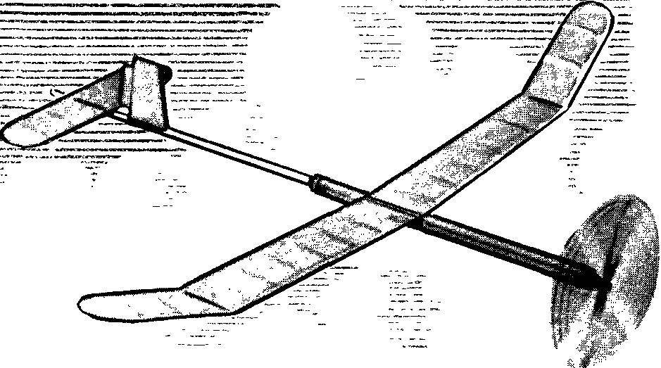
The basic data model
Wingspan, mm: 1030
Overall length, mm: 1037
Bearing area, DM2 : 13,9
wing — 11,1
stabilizer and 2.8
Takeoff weight, g: 162
Mounting angles, degrees,:
the wing is 2.5
stabilizer — 0
Alignment, % SI: 60
The direction of flight:
motor mode — the right turn
planning — the right turn
V. TYUTIN, master of sports, head of the society, Arzamas

 Analysis of the number of participants in youth competitions of aeromodellers in the expense of building a traditional school clearly indicates a much higher availability of gliders compared to rezinomotornaya. This is understandable: because in the end, the last is the same as the gliders, but are equipped by Moto installations, bringing the sharp complexity of not only manufacturing, but, more importantly, adjust Svobodnaya.