
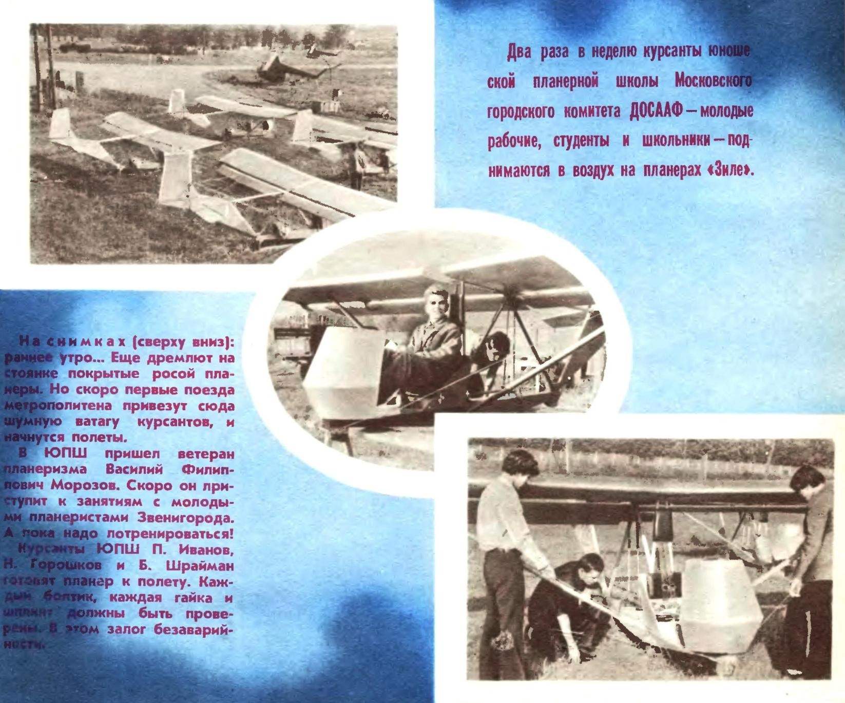
 “Suli’s not pie in the sky, give it to the bird in hand…” So says an old Russian proverb. Don’t know whether it was guided by the famous Lithuanian designer Bronis Oszkinis, creating your initial glider training, to which he gave the name (in Lithuanian “ZIL”). At the all-Union meeting of workers and youth gliding schools and the design of the asset held by the magazine “modelist-Konstruktor”, “Tit” was unanimously recognized as the best ka date training glider. This car can now be seen on many club airfields in our country. Very simple in design and reliable in operation, it has won wide sympathy not only of the younger generation of glider pilots making their first steps in the sky, and veterans of aviation sports.
“ZIL” is available now commercially pilot plant DOSAAF of the Lithuanian SSR. However, it could successfully manufacturing and other companies with the most modest equipment, such as furniture and music factories, woodworking shops, and with appropriate expert guidance to build glider “ZIL” is possible in the model aircraft laboratories and school workshops. The word “tit” in our hands. It remains only to take the initiative.
To meet numerous requests of readers and the demands of various businesses, the editorial begins to print the working drawings and a technical description of the airframe, which should contribute to the further development of youth gliding school and gliding.
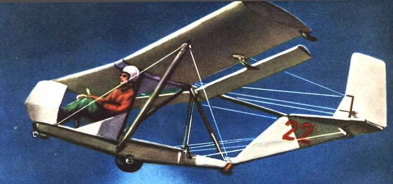
Glider Bro-11-M “Zile” in flight shown in the photo, its scheme in three dimensions — in figure 2, and Fig. 3 — the details. The rest of the readers will find in the captions to the drawings. Figure 1 presents the exposure of the airframe, which should facilitate further reading of the drawings of individual parts and components and to give an idea of Assembly technology.
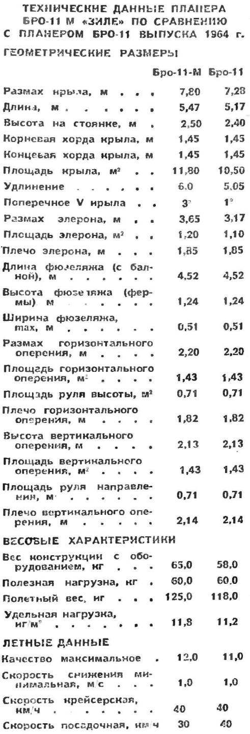
Years of operation of gliders initial training, created by designer B. Hoskinson revealed their characteristics and deficiencies, which were very fully considered in the design of Bro-11-M “ZIL”. In the technical characteristics of this glider, is given below for comparison, separately provided data to the previous, known models of this glider Bro-11.
Wing glider Bro-11-M has a very simple and typical glider design, which can be used as a basis for independent design and construction similar in purpose aircraft. This is confirmed not only by the work of B. Oskinis creating a few variants of the airframe with this wing, but many fans, to build a variety of gliders and motor gliders. Of course, each individual case must be taken into account the requirements of strength: wing, in question 3 of this article are intended only for operation in UPS (potty with a winch PLM-6) in the case of installation on any other aircraft (e.g. glider) requires appropriate amplification.
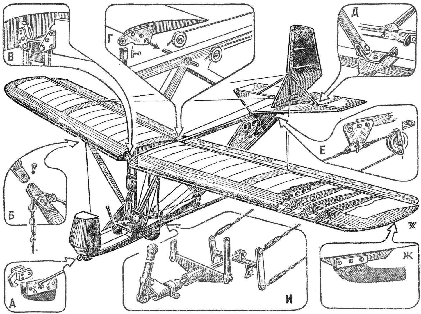
Fig. 1. The overall design of glider Bro-11-M “ZIL” and details:
A — tow hook and the front rubber stop; farm attached to the fuselage with bolts Ø 8; B — the design of the upper mount of the strut to wing attachment lugs and stretch marks; — fastening the spars of the wing to the vertical strut of the farm (bolts Ø 8 mm), dural lining thickness 4 mm; G — suspension design of the Aileron and rollers for the cables of the elevators to the farm of the fuselage; D — mounting of the lower eyelet of the strut of the stabilizer and the linkage of the Elevator; E — rocker roller control cable elevators and the rudder linkage; Rail safety emphasis on wing (dubbed rubber with a thickness of 15 mm); And — the design of the mechanism for controlling the ailerons (vertical tubular thrust) and elevators (duplicia rocking, cables).
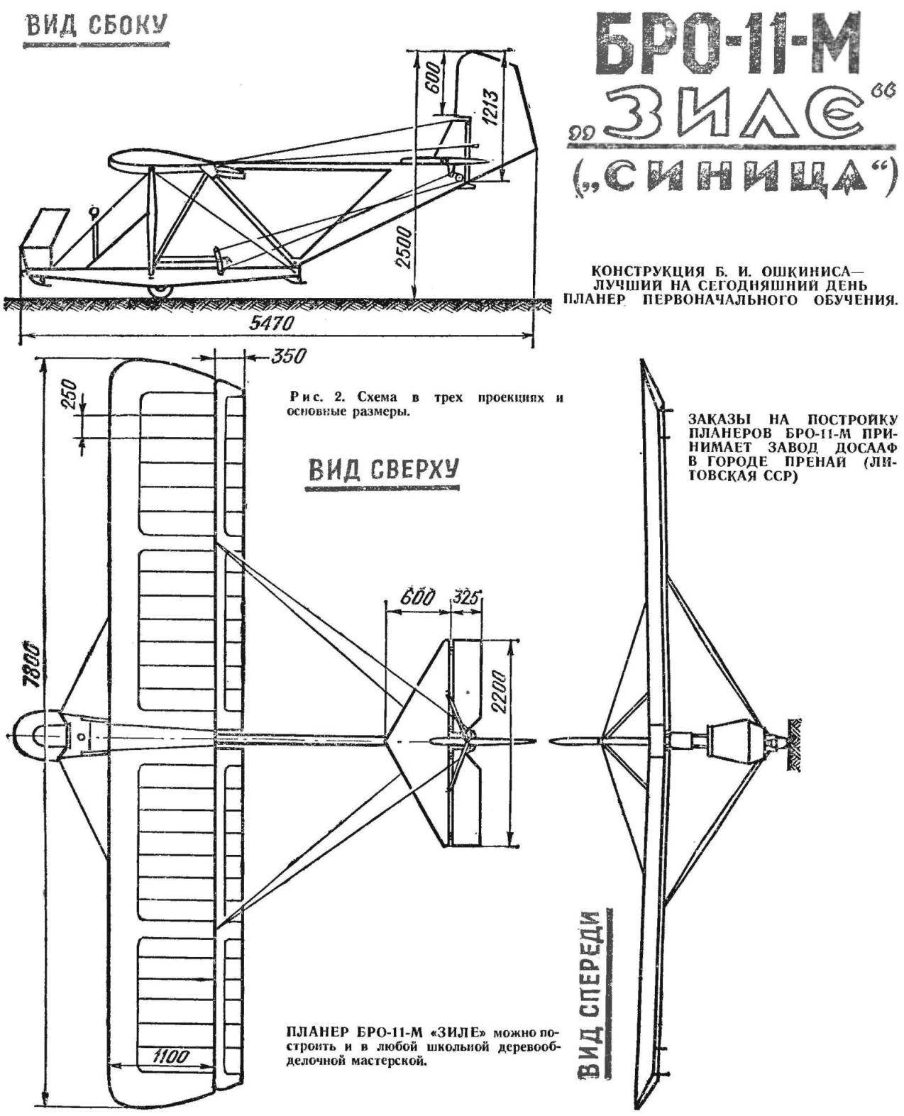
Fig. 2. Scheme in three dimensions the principal dimensions.
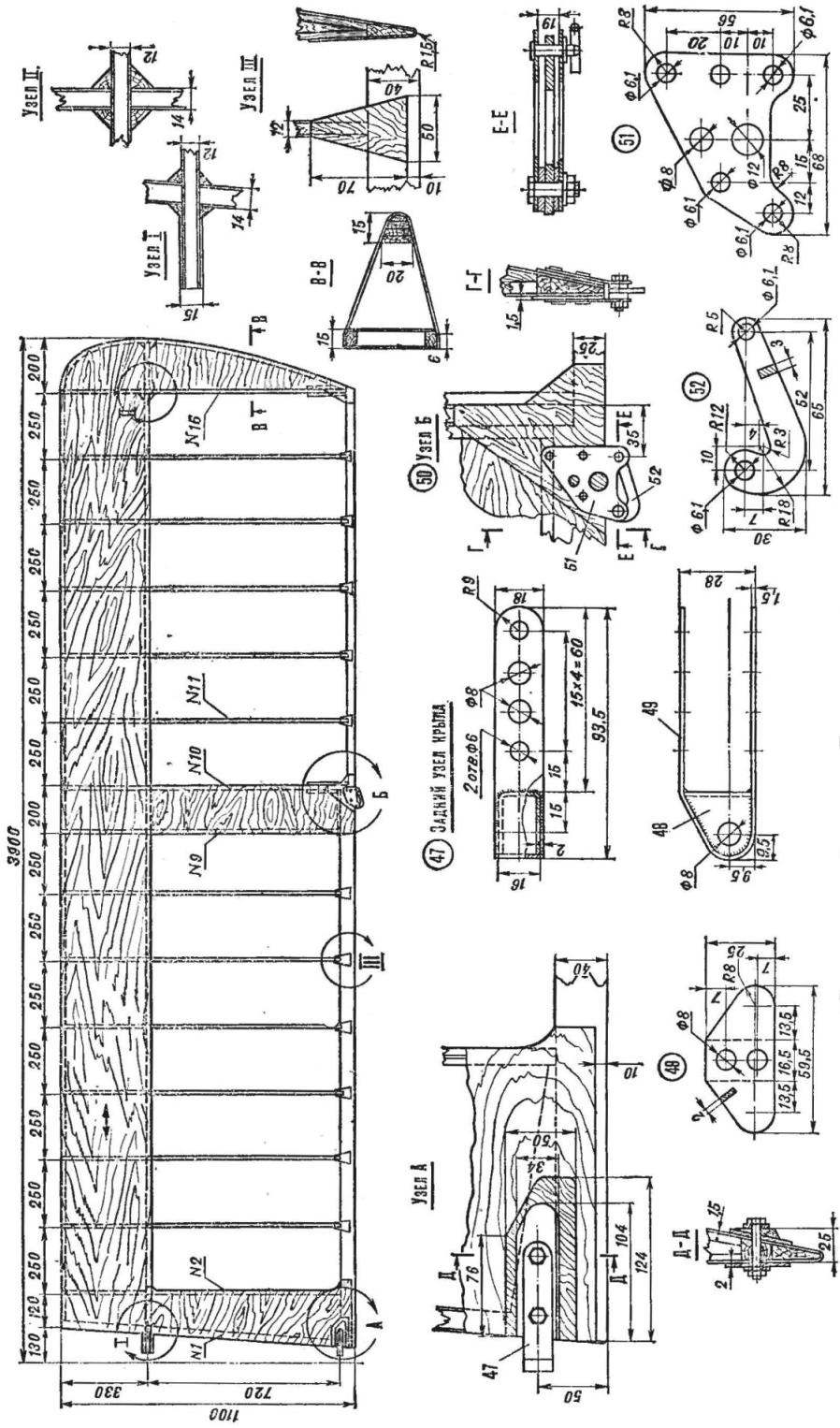
Fig. 3.
Wing Bro-11-M consists of two symmetrical halves (right and left), made of wood and plywood, which are fastened to the farm of the fuselage for the root of the rear spar and stringer. Each half-wing is fixed with a brace, reinforced upper end to the middle part of the spar, and the bottom — to the farm of the fuselage.
Set each wing (see Fig. 2) consists of box spars, 17 ribs, front and rear stringers end of the arc, plywood sheathing, brackets and bosses. Metal nodes (Fig. 3) are mounted on the frame of the wing partly to its Assembly (spar and ribs), the rest are mounted on the assembled frame. Figure 3 shows the rear wall of the wing and lock the shank of the braces. Both of these node are put after the wing Assembly on the rear stringer. The rear site is secured with two 6 X 32 screws with washers and nuts M6. Place attachment is enhanced by plywood pads and ash rake 8X34X104 mm. Lock braces reinforced with three steel rivets Ø 4-6 mm. Hinged hook lock (52) is rotated on the M6 bolt that has been cut and fastened between two washers 3-5-16 mm. Castle contra roller, 6X16 mm, in the lower end of which is inserted a pin.
The wing spar (No. 11, 1976) consists of two solid pine shelves section of 10X20 mm, reinforced podkachali of slats cross-section 10X10 mm, three bosses, fourteen pillars and two end rails. Spar after Assembly, carefully vystragivaetsja jointer and glued on two sides with plywood with a thickness of 1 mm. the fiber Direction of “shirt” are shown. The root part of the spar in place of the attachment to the fuselage is reinforced with plywood stickers 1X65X24 mm. the Node consists of Two plates D16T 1.5 mm thick, remove the caps from the pipe 20A of the brand Ø 8— 10 mm In the middle part of the spar is enhanced rails 5Х12Х135 mm glued on both shelves, and plywood plates size mm. 1X135X54 In this place, between ribs # 9 and # 10, a mount of the strut of the wing. The node is welded from steel plate, two necks and sleeves.
Butt and strut nodes М5Х21 bolted with washers and castellated nuts. The roller serves for coupling the wing to the fuselage.
Profiles of the wing and Aileron are shown in the table are the intercept, which facilitates their tracing in full size. Like the wing and the Aileron have a positive spin on the order of +2°, which is to improve the efficiency of the wing at high angles of attack (stall occurs first in the middle of the wing). The required twist is obtained by a slight bending of the spar in the stocks, before covering the frontal part of the wing with plywood. After covering the wing and keeps the twist.
All ribs have the same profile and chord, but different in design. So, rib No. 2-9 and 11-14—beam, going to the glue and the nails of the four strips cross-section of 5X5 mm, two bosses and plywood walls 1 mm thick with holes (to facilitate). The root rib has a reinforced structure (box section). The shelves are glued strips of 5X12 mm. Stands adjacent to the holes for spars are the cross section of 10X12 mm, the remaining struts and bracing — 5X12 mm.
In the walls of the front part of the rib cut holes for ventilation. Reinforced rib No. 10 and 15 are similar in construction with rib # 1 and have the same cross-section reek.
To the shank rib No. 10 glued bottom boss size 14X52X185 mm. Shank and boss pasted on both sides with plywood 94X210X1,5 mm, over which are pasted two strips 8X10X185 mm To the lug is mounted on the three bolts M5 bracket for the Aileron cut out of D16T duralumin of a thickness of 3 mm, the eyelet bracket vclean steel bushing internal diameter of 6-8 mm. Shank rib No. 16 has a similar structure, only the boss is used to protect the wing tips from hitting the ground.
Ailerons — outboard type, i.e. they are not embedded in the wing, as is customary, and suspended under the wing on two points. One hinge is located on the farm of the fuselage, the other on the bracket rib No. 10. Unusual is the large scale ailerons, almost equal to the wing span. These reached their high efficiency combined with ease of manufacture and maintenance.
The Aileron frame consists of longitudinal members 16 of the same rib, front and rear stringers, skins and brackets. The location of ribs in a set of symmetrical wing ribs. The spars consist of the pine plank section 8X55 mm, reinforcing the plywood with double-sided stickers in three places. Reinforced the Aileron rib No. 1 consists of pine slats size 6X55X315, covered with 1 mm plywood on the outside — along the entire length, inside — 122 mm, measured from the toe of the sock rib. Reinforced rib number 10 is assembled from two shelves section 5X7 mm, two brackets in the toe with a boss from among them, plywood walls, small knize at the end, but also bosses and knize in the middle of the ribs for mounting hinge of the Aileron. Design normal rib the same as rib No. 10, except that the average boss with cnica do not exist.
The horn of the Aileron with the ear of the root hinge is made from duralumin with a thickness of 2 mm. At the bottom of the hole Ø 8.1 mm vkladani sleeves from steel pipe Ø 6-8 mm. Hog secured to the outer side of the rib No. 1 three screws 6— 20 mm Bracket Aileron mounted on the wing rib No. 10 two same bolts.
(To be continued)
Recommend to read
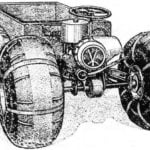 “HINGE” THE ROVER
The vehicle is made according to the scheme proven by the tractor "Kirovets". He has the same "breaking" the frame and drive on both bridges. What gives? First, the good permeability....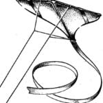 AEROBATICS OF A KITE
That a kite can be under the control of a pilot to perform almost a full range of aerobatics, very few people know. It should be noted that the modelers individual samples of superslow...
