Now about the history of the appearance of this device. The idea of creating a light ship amphibious hovercraft for individual use or athletic purposes began in the walls of the TSKB on SPK: here, in addition to creating hydrofoils in the development of wig, but very large and heavy, suitable for carrying large loads. The design also checks carried out on self-propelled models are of smaller size and weight. During these tests it became clear that such manned model itself can be a great vehicle. Naturally, when minor changes and a much improved design. The idea is actively supported by P. E. Alekseev. The basis was adopted lightweight design V. Moses. But mass production of such devices failed. However, the design group led by Sergei Prikhodko performed single-item production vehicles “Toros-1”, the first samples which are already in service in the Tyumen region, Irkutsk, Novgorod and Yakutia.
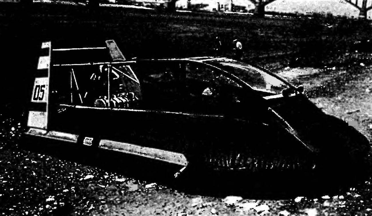
Fig. 1. The vehicle is a hovercraft (General view):
1 — wheel, 2 — keel, 3 — blade, 4 — engine, 5 — duct, 6 — superstructure, 7 — stringer attachment of the duct, 22×1,5.
Fig. 2. Add-on:
1 — motor, 2 — upper stringer (tube 45×1,5 mm), 3 — back front wheelhouse (rough 30×1,5 mm), 4 — spacer (tube 30×1,5 mm), 5 — seat mount Assembly (8), 6 — brace of the lamp (tube 30×1,5 mm), 7 — fringing of an aperture (pipe 30×1,5mm), 8 — hour average period (pipe 30×1,5 mm), 9 — front wheelhouse (steel 30×1,5 mm), 10 — front brace (pipe 30×1,5 mm), 11, 16 and 17 of the upper cross member (tube 30×1,5 mm), 12 — front engine mounts (tube 45×1,5 mm), 13 — lower cross member engine mounts (tube 45×1,5 mm), 14 — stern stringer base (tube 45×1,5 mm), 15 —brace motor (tube 45×1,5 mm), 18 — cross base (tube 45×1,5 mm), 19 — step back (tube 30×1,5 mm), 20 — cross the border (steel 30×1,5 mm), 21 — footrest, front (tube 45×1,5 mm), 22 — arc bow -, 23 — bow stringer base (tube 45×1,5 mm), 24 middle cross member engine mounts (tube 45×1.5 mm).
R and S. 3. Platform:
1 — cross member (tube 45×1,5 mm), 2 — stringer outer feed (tube 45×1,5 mm), 3 – stringer aft inner (tube 30×1,5 mm), 4 —stringer external nasal (tube 45×1,5 mm), 5 — stringer inner nasal (tube 30×1,5 mm), 6 – bow arc (АМГ5М, pipe 45×1,5 mm).
Fig. 4. Fencing screw:
1 — shell screw, 2 — keel, 30×1,5 mm, 3 — spacer, 30×1,5 mm, 4 — the ending of the keel, 30×1,5 mm, 5 — toe keel, 30×1,5 mm, 6,7, 8, 9 — connecting elements (pipe 30×1,5 mm).
Fig. 5. Duct.
Fig. 6. Cutting out duct.
Fig. 7. Flexible protection:
1 — pocket dome, 2 — cylinder, 3 — bow veil 4 — dome, 5 — aft curtain, 6 — bolt 7 — washer, rubber, 8 — clip.
R and p. 8. The lid of the container, the right side (left is mirror image):
1 — aft extremity, 2 — apron outer, 3 — panel, 4 — apron cross, 5 — a fore end, 6 — tape (24×3920 mm), 7, 8 and 9 external pockets, 10 — redan, 11 from the protective panel, 12 Kil (5×2 mm), 13 — apron internal, 14, 15, and 16 internal pockets, 17 — grommet, diameter 10 mm.
The idea of an ultralight machine the sub-Mariner still has mass, V. Moiseyev was made the proposal to publish the most comprehensive material on TSIT “Toros” in our magazine.
The basic principles followed by the authors in the design of this device are: simplicity, collapsible, minimum weight and low cost. These requirements are developed in a witty formula of the three T “tube-cloth-rope”.
Some differences between the machine represented in the pictures and drawings related to the fact that “Taurus” is constantly being improved, and design documentation, as always, lags behind.
The apparatus consists of the following main parts: a tubular frame, engine, rudder, duct and flexible fencing.
In the manufacture of the frame, which consists of a platform, superstructure, and railings of screw, used duralumin (D16T) pipe of different diameter. Connecting them is carried out mainly with the help of brackets and clamps. To enhance the connections and protect them from damage set duralumin or plastic tool trays, and under heads of bolts and nuts are placed washers or large diameter plates that are crimped then the pipe.
Part of a superstructure is the deckhouse, which contains two suspended seats for the pilot and passenger, and controls. On the last models of apparatus the pilot seat is made for comfort and control apparatus. The cabin in the stowed position closes the lamp double riveted duralumin construction with glazing of 3 mm of Plexiglas and winepros MA-20. Such a design of the lamp quite difficult and time-consuming for individual construction of the apparatus. It can be made from the same soft fabric used in the manufacture of the sheathing of the keel and apron, closes the forward part of the cabin. By the way, in the first devices and was.
Arguing about the difficulties that can вб5йикнуть during the construction of the apparatus, it should be noted that the greatest number of problems will be in the manufacture of “soft” part. It consists of the nose apron, duct, plating (keel, as well as from the dome, closing the add-in from below the cylinders, bow and stern curtain. The latter together form a flexible enclosure apparatus which serves to create the air cushion and lifting TSIT.
The most difficult to produce “rag” items — duct and cylinders. Before their production, it is desirable to make “fitting” out of simple cheap cloth, and then fit it under the size of the device, to transfer the pattern on real material.
The duct consists of three main parts: inlet, middle and bow. Latest stitched together and the air intake connects to the middle part of a combined fastener (“zipper”double “burdock”). To increase the strength of sutures and their tightness they are glued with a synthetic rubber.
The air intake has a soft partition that separates the bleed air flow into two and puts out his spin. Entrance of the air intake connects to the sides and the bottom cross member of the fence screw. The upper and lower parts of the duct are sewn together. Line B is attached through the stringers to the superstructure of the apparatus, and line And sosotoyalsya with external apron tires of the cylinder.
The container consists of tires and cameras. The lid is collected from the cloth forming its cylindrical part, as well as the aft and forward end of that stick to cloth. In addition, the tire sewn pockets into which are inserted the outer and inner stringers of the platform; there are also aprons used to connect the cylinder to the duct of the nasal veil and a dome. On the lower part of the tyre glued the sponsons and keel. The sponsons are designed to disrupt the laminar boundary layer and improve performance of the device during movement on the water surface. These design elements are manufactured by casting of urethane rubber. Toe cylinder has a hole with a grommet that is attached to the forward arc.
The camera container is best to glue the rubberized fabric stamps 202-2N (type BCC), which usually make inflatable boats. In form it is close to the tyre, but the length and the diameter should be 10% more. In this case, tire wear is reduced, and reduces the risk of accidental damage to cylinder. To eliminate the possibility of flooding of the apparatus if the damage to the camera, it is necessary to make at least two sections.
The dome of the apparatus is a cloth covering his bottom and having openings for the passage of air from the air duct. It is attached with pockets to the aft cross-beam of the platform and to the forward arc, and by domestic and cross aprons cylinders prinorovilsya.
Aft dome aft curtain fastened, having the form of a “bag” with holes near its “neck” to boost the veil.
Bow veil prinorovilsya to the pockets of the dome at the same time with his apron covering felling and the apron, duct, and on the sides — the lateral aprons of the cylinders.
It is now necessary to say a few words about the material from which made the details of the casing and flexible skirts, in addition to the chamber of the cylinder. All they are made of technical nylon. Can be used for these purposes and other nylon or Dacron fabrics of bright colors. Basic details (the skin of fins and the sides of the deckhouse, bow the apron, parts of the flexible fencing, except curtains and pockets) is made of nylon fabric with two to three impregnation of a urethane prepolymer (synthetic rubber) with the addition of color fillers. Technology of impregnation of the fabric detail is very time consuming not harmless (it is necessary to observe the same precautions as you would with epoxy) and requires certain skills. So for those who are going to make such a device, advise to try to buy for these purposes, the awning fabric “Teza”, which covers the body heavy cars and “Gazelle”.
After making all of the parts of the frame, plating and flexible protection, you can begin to assemble the machine – it Seems that even a summary of the build process will help you understand the purpose of some structural elements of the apparatus and may push your design ideas to a new, more successful solution.
The Assembly machine begins with the lacing connection parts of the flexible fencing with each other, and then with the air ducts and the apron is cut.
A few words about the lacing. For her slip up (without damaging the threads of the fabric) holes on the second parts of the parts. Lacing runs a nylon cord in the plastic shell which will protect the cord and the hole from damage.
The Assembly of the power frame begins with the frame of the superstructure. Dock the bottom of the stringers, the struts of the lamp and stand felling. Then connect the rear rack of the wheelhouse, and the upper stringers. Then assembled the frame are mounted the seat, control stick and the Gaza strip, the covering felling and the tape is for fuel cans. Installed engine mount and is attached to the top stringers to the frame of the cabin. Mounted sides of the propeller, powerplant and aft upper cross member located above it. Installing the air screw, go to the Assembly platform. Bow-arc is inserted into the pocket of flexible fencing of the dome. Joined outer and inner stringers and inserted into pockets of the containers. After the external stringers are connected with the nasal arch, the aft cross member is fastened to the dome and is mounted together with the other cross members to the outer and inner stringers of the platform. Then dock stringers pass through the ducts and into the pockets of the ducts. Now you can pump up the cylinders, put the superstructure on the platform and attach the aft part of the intake to the sides of the screw. Install the keels, wearing them on the hull and connect them with pipes. Then hang the wheel, match the intake with the air duct and secure the stringers to the frame of the superstructure. Guide the cables of traction and steering control of the Gaza strip. Then, scontrib all connections, setting the cans of fuel, and connecting them to the engine, start the engine and very carefully — go ahead!
But first please note some of our recommendations in piloting vehicles. The first thing that draws your attention to this balance: the center of gravity of the apparatus should be slightly (200 mm) behind the center of pressure of the airbag, which coincides with the center of its area. Proper balancing ensures maximum speed and stability on the course with good maneuverability. If this floats TSIT with the trim on the nose (80 mm) to a speed of 40 km/h. At speeds over 40 km/h it is already “on an even keel”, and 60-70 km/h — with trim by the stern (80 mm). For balancing, use a bag with a tool, a payload, or a bag of sand.
A little bit about safety while operating the machine. If someone really wants to make a turn overkill (that is, to roll up the cylinders) and that is unfrozen in the ice-hole, it is best to:
to accelerate to maximum speed in the wind,
— sharply to give the control stick left or right
— and when the machine enters in turn, to dramatically throttle.
It was also easier to roll over in a strong wind, high wave, right turn, placed high loads or when flying at half-mast cylinders. To prevent such coups is undesirable: if it fails the engine will bend the blades, and they manage to overwhelm much of what is next.
During the years of testing such devices are overkill only happened twice, but impressions were very bright. Therefore, to get out from under the machine, make u-turns at a speed not exceeding 25 km/h and at maximum engine speed (full throttle).
So, go ahead! You now not afraid of any obstacles.
V. MOISEEV, V. KUDRIN, our special correspondent.
Recommend to read SLIT WITH ONE BLOW It would be good to have a set of different blades to the hose for irrigation, including end nozzle in the form of a slot: it has its advantages. And most importantly — this is easy to... RESCUE TENT Plots is small. And when every square foot counts, then the space allocated to garages and outbuildings — not an easy task. An acceptable solution may be tent structures. Especially...