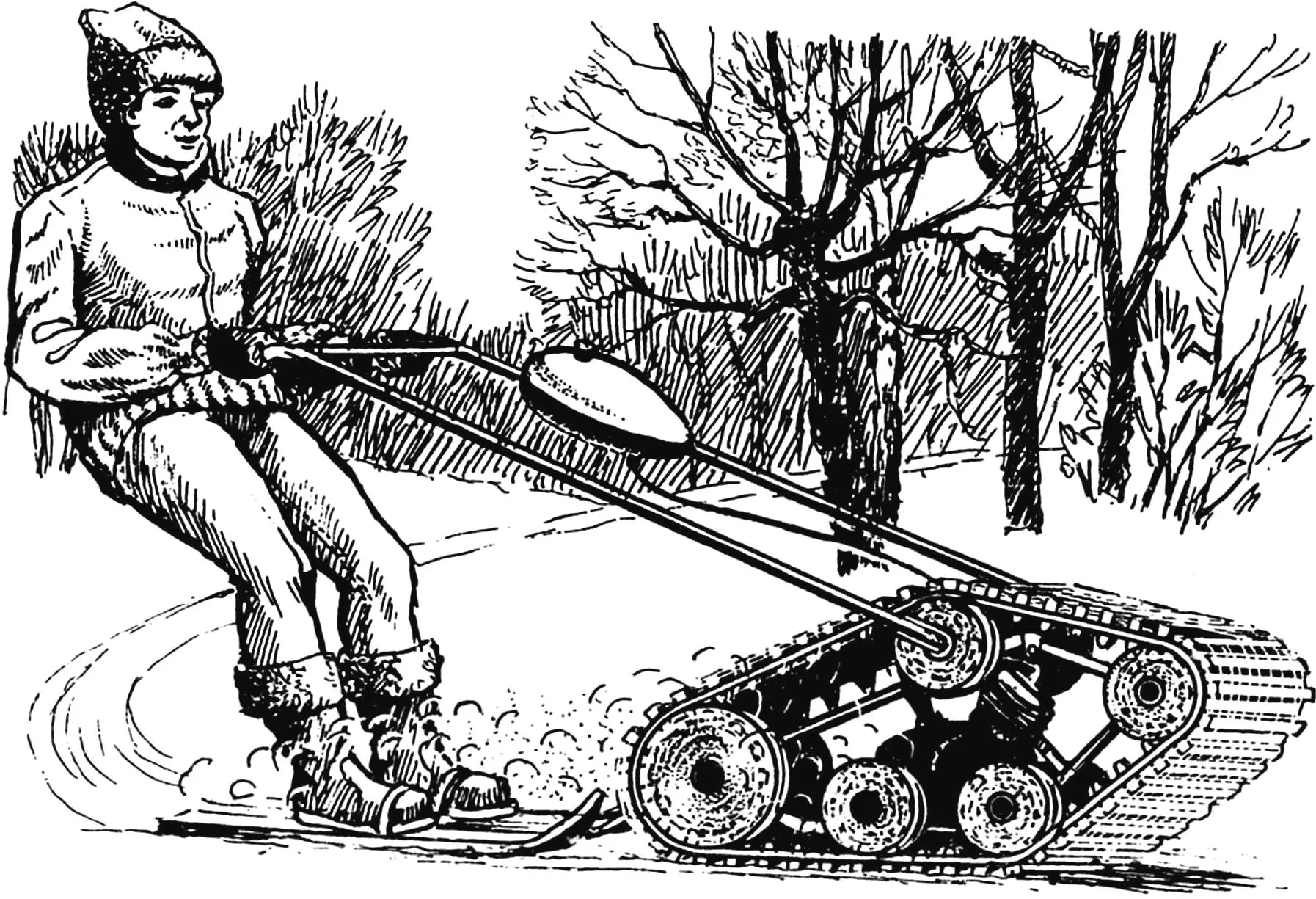
Many have probably heard of an interesting winter sport — skijoring, in which skiers compete while being towed by a motorcycle. In northern countries, a similar sport is cultivated — towing a skier by a horse.
The vehicle we want to introduce you to will allow you to fully experience the delights of high-speed skiing without resorting to the help of a horse and without burdening a friend — a motorcyclist (who would want to go out in winter on an open two-wheeled machine!).
We’re talking about a simple tracked motor towing vehicle called “Seal” based on a moped engine V-50, which will rush you across a snow-covered plain at a speed of 30 km/h.
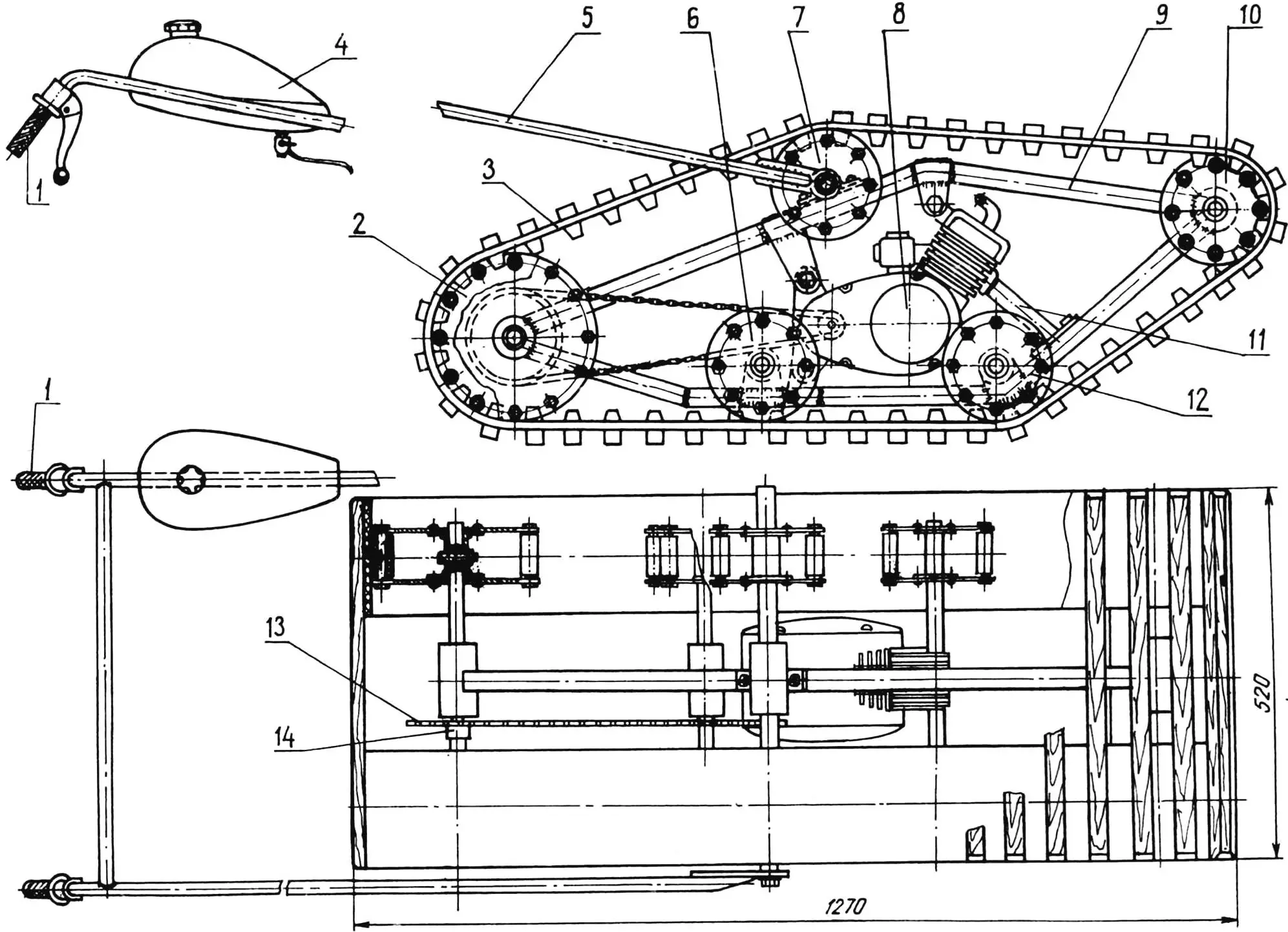
1 — control handles of the motor towing vehicle; 2 — drive roller; 3 — track belt; 4 — fuel tank; 5 — drawbar; 6,12 — support rollers; 7 — tension roller; 8 — V-50 engine; 9 — frame; 10 — front roller; 11 — exhaust pipe; 13 — drive chain of drive rollers; 14 — drive shaft sprocket.
As can be seen from the drawings, it is arranged simply. On a flat frame welded from square-section steel tubes, a two-stroke engine (such were installed on mopeds “Riga”, “Carpathians” and others) and five bearing units are mounted, in which five tubular shafts with rollers fixed on them can rotate. The pair of rear (large) rollers is the drive, for their drive a bushing-roller chain is used, connecting the small sprocket on the engine and the large sprocket fixed on the drive shaft of the motor towing vehicle. A drawbar with motorcycle-type control handles is hinged to the upper shaft on which a pair of tension rollers is mounted. In addition, a moped fuel tank is located on the drawbar.
Start the work of manufacturing the motor towing vehicle by selecting bearings. It is from their geometric parameters that the dimensions of bearing units, shafts and rollers will depend. Of the most common, bearings 205 are best suited, although others are quite acceptable.
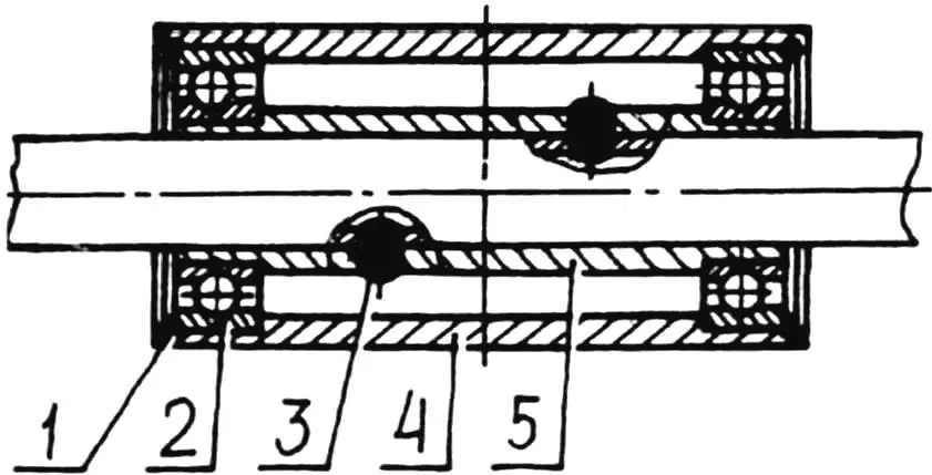
1 — split lock washer; 2 — bearing; 3 — electric rivet; 4 — unit housing; 5 — transition sleeve.
Turn the bearing unit housings from sections of steel pipe 58×4 mm. Essentially, it’s enough to face these sections on a lathe, make grooves for bearing races and cut annular grooves for split lock washers.
Roller shafts — from 20×3 mm pipe, install them into bearing housings using transition sleeves fixed on the shafts with electric rivets (this is what connecting elements are called, obtained by electric welding, when a hole is drilled in one of the mating parts, and then, when assembling the parts, it is welded; the metal filling the hole is called an electric rivet).
For assembling the motor towing vehicle frame, we recommend using the simplest jig-plate — a flat particle board on which the side projection of the frame is drawn.
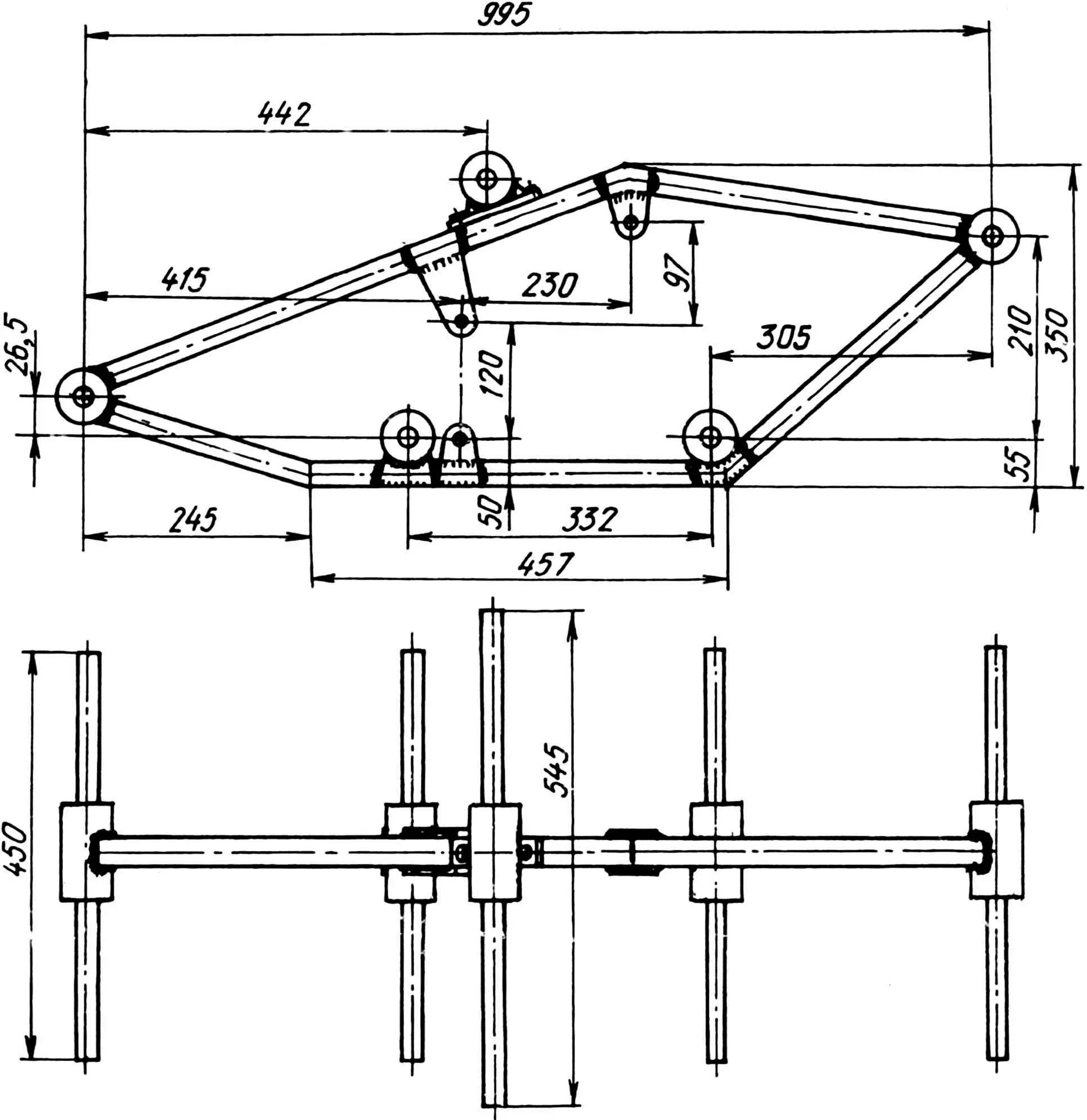
First of all, fix the bearing housings in the centers of the roller locations with long studs. At the same time, try to ensure the parallelism of their axes. Otherwise, it will be difficult to achieve normal operation of the tracked drive.
Next, select suitable pipes, preferably square section, since bending such is easier — you just need to cut a wedge with a hacksaw, bend it according to the image on the plate and weld the resulting joint.
Prepare two frame pipes — upper and lower — in the indicated way, then connect them to the bearing units using soft steel wire. To do this, drill holes in the pipes in the area of the front and rear bearing units, through which pass the wire, which at the same time loops around the bearing units. Next, using a wrench, tightly twist the wire so that something like a “telegraph” bandage is formed (this is what the connection of a wooden telegraph pole with a base-stub is called). Attach the frame pipes to the remaining bearing units (except the upper one) also with wire twists.
After carefully checking the parallelism of the bearing housings, tack them to the frame by welding, then remove the wire and check the frame again, straighten it if necessary. Finally, reinforce the joints of the frame with the lower bearing units with gussets made of steel sheet 2 — 2.5 mm thick.
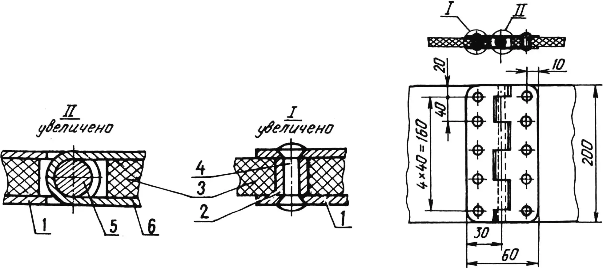
1, 6 — half-loops (steel s1); 2 — sleeve (duralumin, pipe 6×1); 3 — track belt; 4 — rivet (duralumin Ø4); 5 — loop axis (steel Ø6).
First cut out the engine mounting brackets from thick cardboard and work out their shape and dimensions. When the contours are finally determined, cut the actual brackets from 3 mm thick steel sheet according to the obtained templates, drill 8 mm diameter holes in them. Fix the brackets with bolts on the engine, then pull the engine to the frame using wire in accordance with the image on the drawing or on the plate. Next, tack the brackets by welding, check the accuracy of their location and finally weld them to the frame.
The engine does not have a special muffler — its function is performed by the lower part of the frame. To do this, connect the engine exhaust window to the cavity of the square frame tube using a pipe. To release exhaust gases, drill 5 mm diameter holes in the latter from below (at least fifty holes will be needed, otherwise the engine will not develop rated power).
Now about the manufacture of rollers. All of them — drive, support and tension — are the same in design. Each consists of a central sleeve welded from two steel disks and a pipe section, two duralumin disks and twelve (for large rollers) or eight (for small ones) ties. The latter are steel studs with sections of rubber hose fitted on each; the studs are fixed on the disks with nuts. Such a roller design is quite simple and capable of driving the motor towing vehicle’s track.
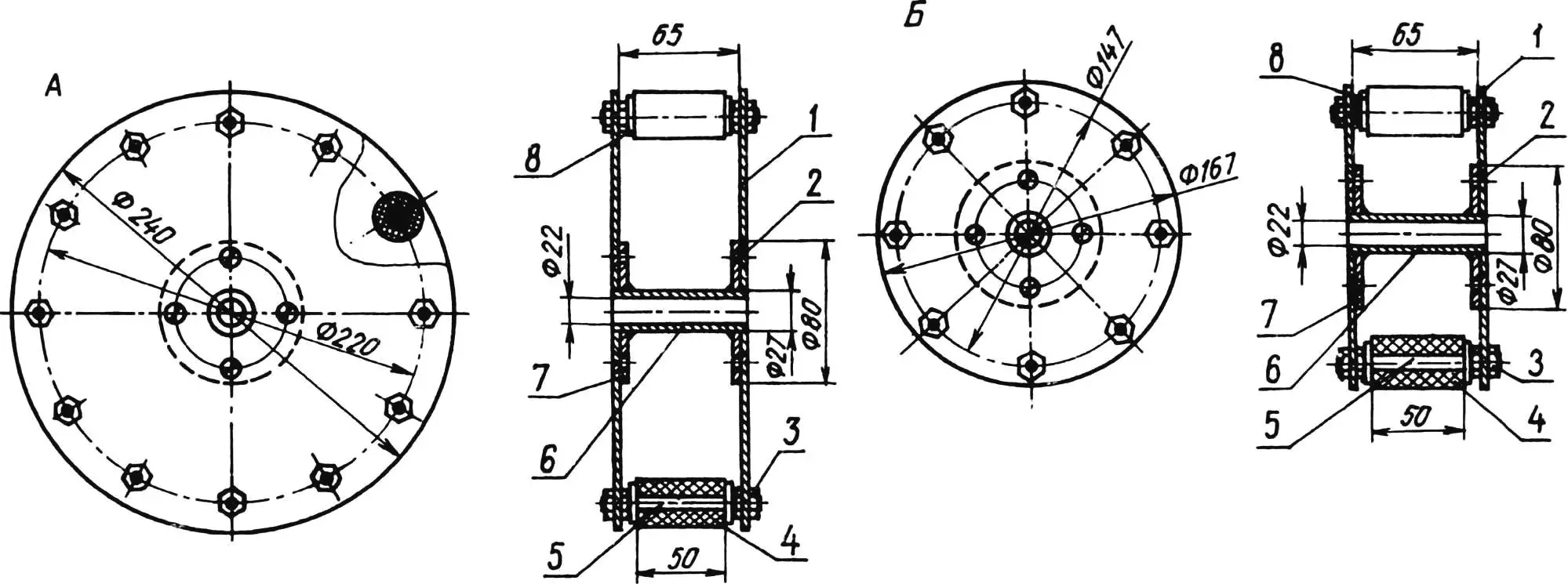
1 — roller disk (duralumin s3); 2 — M5 screw; 3 — M8 nut; 4 — rubber sleeve; 5 — M8 stud; 6 — central sleeve; 7 — central sleeve disk (steel s3); 8 — washer.
As can be seen from the drawings, the upper pair of rollers can move along the frame, thereby allowing adjustment of the track tension.
The drive rollers are fixed on the shaft with tapered pins, the holes for which are drilled in the central sleeves fitted on the drive shaft before final assembly of the rollers.
The “Seal’s” drive consists of two rubber-fabric strips cut from an old conveyor belt and united into a single track by wooden rails — ground cleats. The strips are joined into a ring using a unit resembling a piano hinge. When assembling the track, the distance between the rails-ground cleats is strictly maintained — it should be 57.5 mm. Each rail-ground cleat is attached to the rubber-fabric belt with a pair of bolts with nuts, while the rail is located on the outer side of the belt, and on the inner side — a cleat cut from a 2.5 mm thick steel strip. The cleats allow the drive rollers to “rewind” the track belt, thereby setting it in motion.
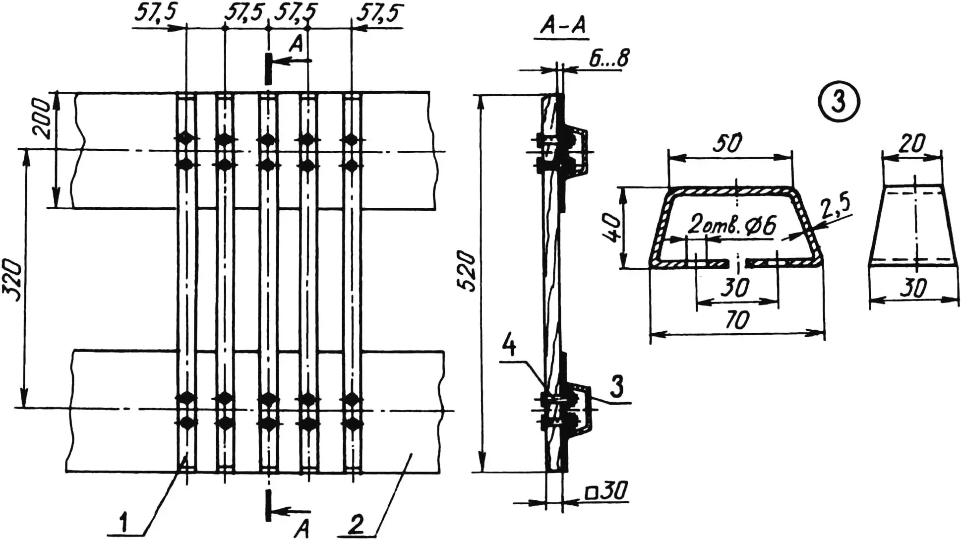
1 — ground cleat (birch rail 30×30); 2 — track belt (conveyor belt s6); 3 — cleat (steel s2.5); 4 — M6 bolt.
The motor towing vehicle is controlled by a drawbar on which motorcycle-type handles are mounted: a rotary “throttle” handle is installed on the right, and on the left — the drive of the clutch mechanism and the gearbox switch from a “heavy” moped.
For the motor towing vehicle engine, you’ll have to slightly modify the standard starting device. Remove the kickstarter pedal and press a pin into the shaft. Start the engine using a handle resembling an automotive one. To do this, put a ratchet on the starting device shaft and sharply turn the handle a quarter turn.
“Modelist-Konstruktor” No. 2’99, I. MNEVNIK
Recommend to read
 Cargo mini moped
I have been a long-time reader of the magazine “Modelist-Konstruktor” and subscribed to it for many years in a row. Then, due to financial difficulties, I had to give it up. But since last... TWO BLADES AND ONE MOTOR
Svobodnaya model helicopter. As they say, is new — is well forgotten old. Not so long ago we introduced readers model airplanes from the simplest Svobodnaya model helicopter — judging by...
