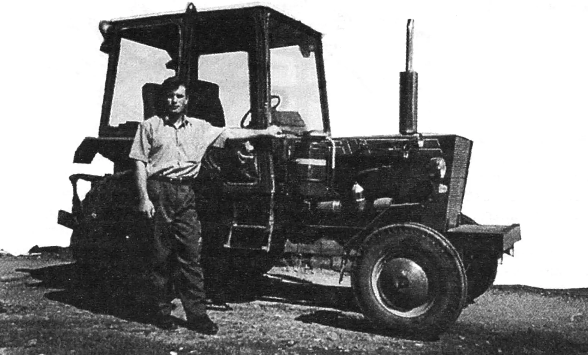
I have long been a fan of the magazine “Modelist-Konstruktor”. Back in my school years I was into aircraft and rocket modeling and made kites. Small-scale mechanization also attracted me. I dreamed of some kind of tractor, especially when I had to dig the garden by the house by hand.
After graduating from the institute, as a young specialist I was assigned to work at a collective farm. There my childhood, or rather youthful, dream of a tractor was able to take on real shape.
One day I came across a stripped-down D-21 engine from a T-25 tractor. After overhauling it and adding a gearbox and rear axle from a GAZ-51 truck, in a year I built my first creation — a mini-tractor.
Over time, shortcomings showed up in the mini’s design: first, the engine, though economical, proved to be weak; second, the rear suspension with small front wheels from a T-40 tractor turned out stiff — on our roads it was rather hard to ride on such a machine.
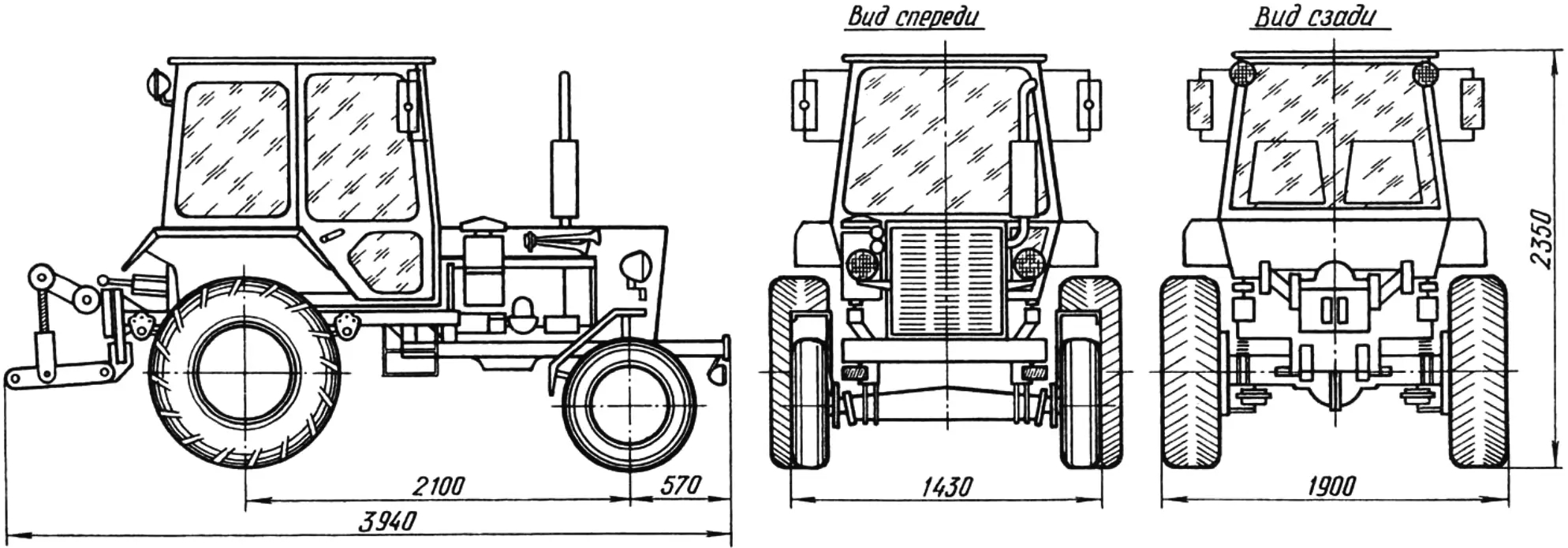
Then I sold my firstborn and with the proceeds bought a more powerful engine — a D-144 (from a T-40 tractor) and a gearbox from a GAZ-53 truck. As the front axle for my new tractor I used the rear axle of an SK-5M Niva grain combine with minor modifications: I slightly turned the hubs and drilled five new holes for the fastening screws of 16-inch wheels taken from a trailed cultivator. For the rear I used a rear axle from a ZIL-157 truck, which I had to cut so that its wheel track matched the front track — this is especially important in plowing, when both right-hand wheels run in the same furrow. By the way: the rear wheel disks are original ZIL ones, but with tires from a GAZ-66 off-road vehicle.
After finishing the axles, I turned to selecting springs. After bouncing on the seat of my firstborn I wanted to ride in comfort from then on. And although the collective-farm mechanics were puzzled (a tractor — and on springs?!), I listened to no one. I attached springs from a Bulgarian electric cart to the front axle, and the front springs from a GAZ-51 truck to the rear. Then I set the axles on a level pad and carefully measured the difference in their height. That difference had to be known in order to make the tractor’s stepped frame.
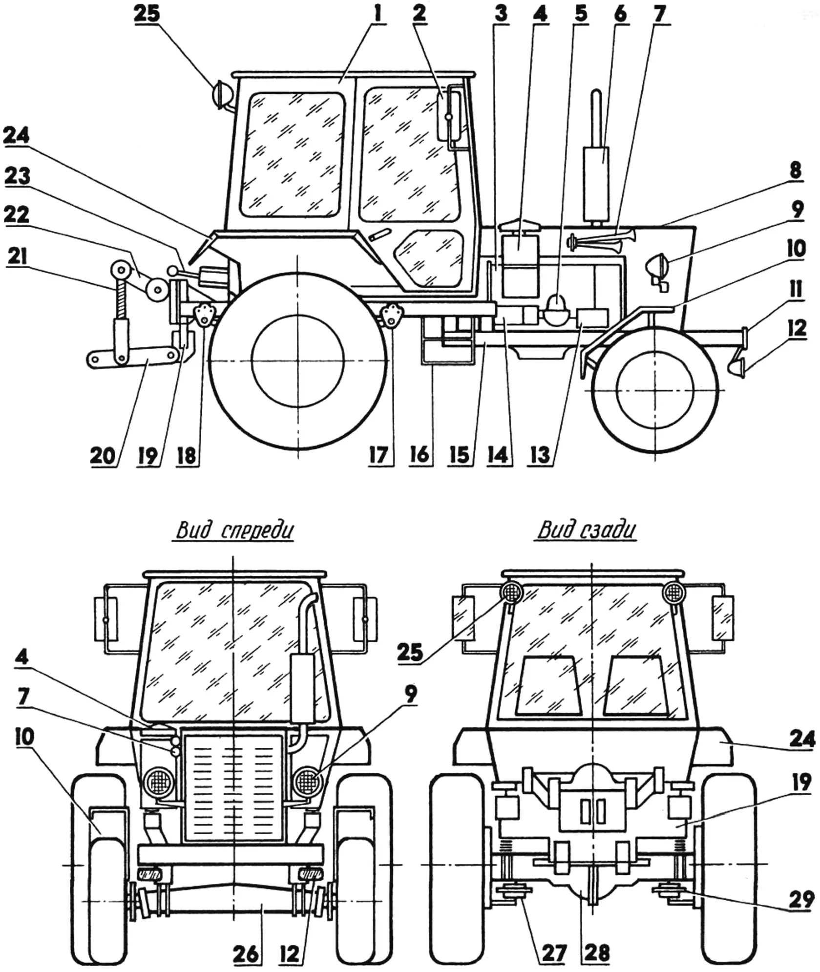
1 — cab; 2 — rear-view mirror; 3 — engine; 4 — hydraulic tank; 5 — centrifuge; 6 — muffler; 7 — horn; 8 — hood; 9 — road headlights; 10 — front fender; 11 — bumper; 12 — auxiliary lights; 13 — generator; 14 — starter; 15 — tractor frame; 16 — steps; 17, 18 — spring brackets; 19 — implement hitch plate; 20 — longitudinal link; 21 — brace; 22 — lever; 23 — hydraulic cylinder; 24 — rear fender; 25 — work lights; 26 — front axle; 27, 29 — brake air chambers; 28 — rear axle.
Implement hitch is not shown in the rear view
I welded the frame as a two-step structure, mainly from 80x80x6 mm square steel tube. I attached the front axle and the power unit to the lower step of the frame. For this I provided matching brackets on the side members: spring brackets taken from the electric cart (bolted on) and engine brackets cut from No. 8 channel (welded on). The engine rests on the latter with its two front mounting points (its rear mounts are described below).
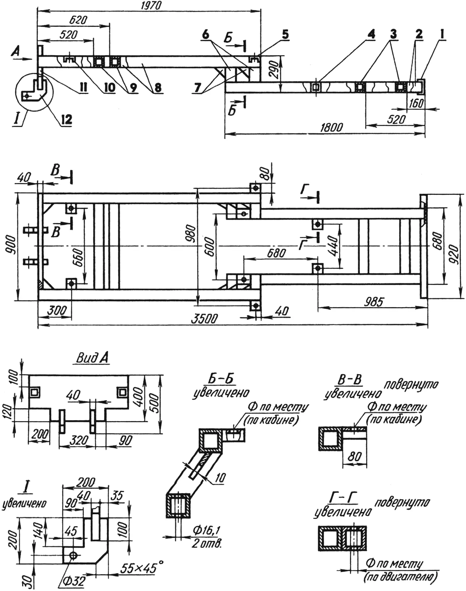
1 — bumper (No. 12 channel); 2 — front side members (80x80x6 tube); 3 — front crossmembers (80x80x6 tube); 4 — engine mounting bracket (80x80x6 tube, 2 pcs.); 5, 10 — cab mounting brackets (No. 8 channel, 4 pcs.); 6 — struts (80x80x6 tube, 4 pcs.); 7 — gussets (steel sheet s10, 6 pcs.); 8 — rear side members (80x80x6 tube); 9 — rear crossmembers (80x80x6 tube); 11 — implement hitch plate (steel sheet s10); 12 — hitch bracket (steel sheet s10, 2 pcs.)
To the upper step of the frame I attached a new-style cab from a YuMZ-6 tractor, after first cutting it at the bottom together with the doors, and the rear axle — using springs and spring brackets from a GAZ-51 truck.
At the front of the frame I welded a bumper — a length of No. 12 channel that matches the height of the side members well; at the rear, a massive steel plate for mounted implements. That, in essence, is the entire tractor chassis.
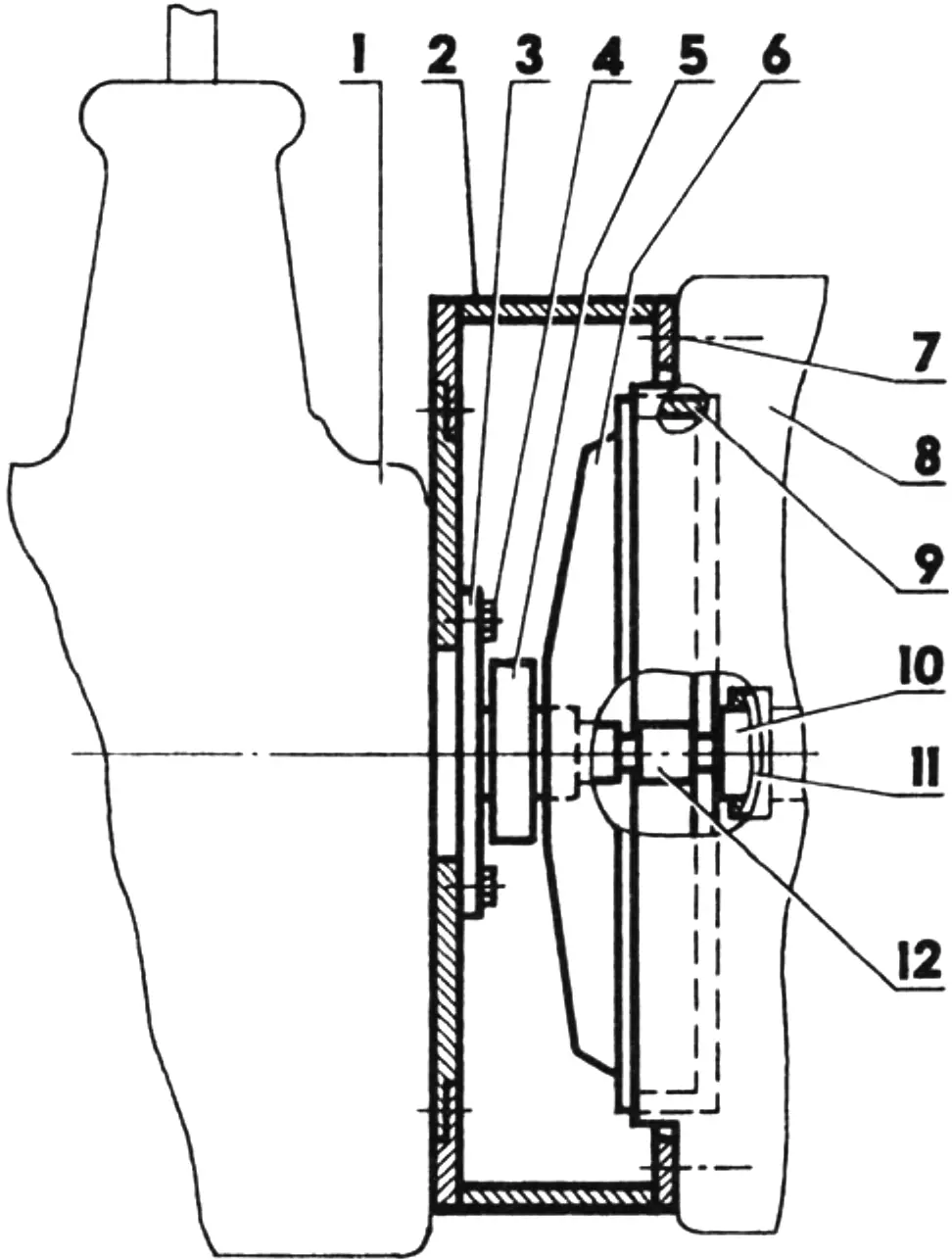
1 — gearbox; 2 — clutch housing; 3 — clutch release-bearing flange; 4 — M6 flange fastening screw (6 pcs.); 5 — release bearing; 6 — pressure plate with driven clutch disk; 7 — M12x1.5 bolt (6 pcs.); 8 — engine rear beam; 9 — engine flywheel; 10 — crankshaft bearing; 11 — crankshaft; 12 — gearbox input-shaft extension
A harder problem for me was mating the tractor engine to the automotive gearbox. A homemade adapter (clutch housing) had to be placed between them. At first I did not know exactly how. But after brief thinking, estimates and sketches I settled on using a hydraulically actuated clutch from the German Forstrit E-302 mower described earlier (I could just as well have used similar units from the German Maral E-281 forage harvester — they are that similar). Incidentally, the steering column together with the steering hydraulic cylinder also came from the mower. Thanks to it, my tractor’s steering is exceptionally light and reliable.
Estimates also showed that for the chosen clutch it was simpler not to pick a ready-made housing but to make one myself. I welded it from thick sheet steel as a cylinder with large-diameter end openings and two side lugs. The front end opening is for the engine rear beam; the rear one is for a cover to which the clutch release-bearing flange is screwed from the inside. The housing is attached to the lower step of the tractor frame by the lugs. At the same time these lugs serve as the engine’s rear supports, because the engine is joined to the housing by its rear beam with six M12 screws. In addition, the housing cover has four M14x1.5 studs for mounting the gearbox.
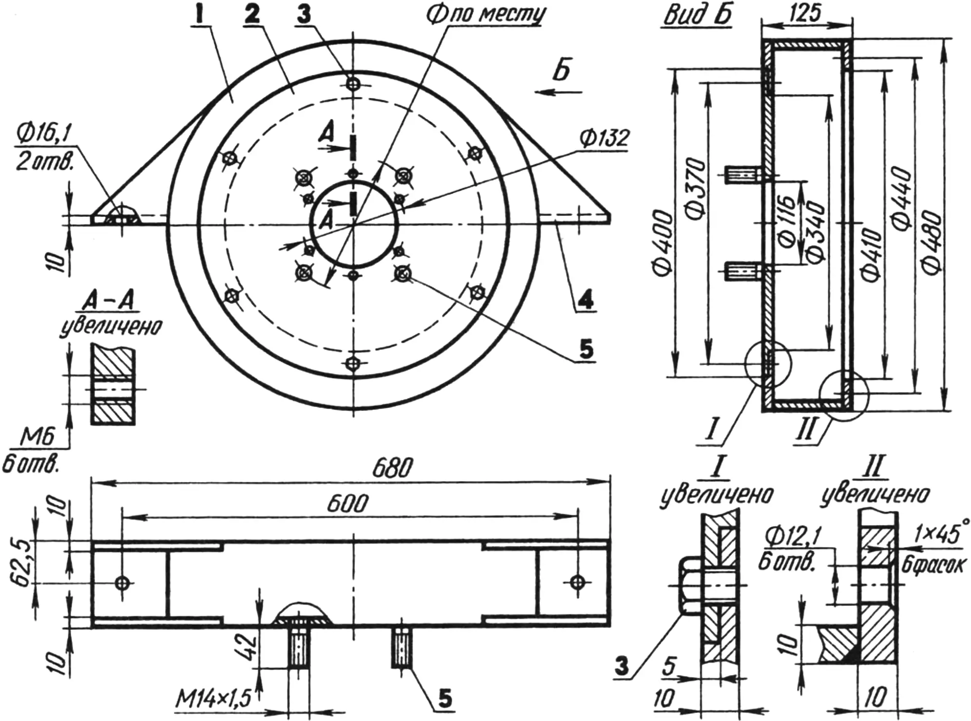
1 — body (steel, sheet s10); 2 — cover (steel, sheet s10); 3 — M10x1.5 cover fastening screw (6 pcs.); 4 — frame mounting lug (steel, sheet s10, 2 pcs.); 5 — gearbox mounting studs M14x1.5 (4 pcs.)
And one more thing. Because the input shaft of the GAZ-53 gearbox did not reach the seating hole in the crankshaft bearing of the D-144 engine, I fitted it with a simple homemade extension.
Thus, when the power unit is dismantled for repair or maintenance, the housing design makes it easy to disconnect the gearbox without disturbing the clutch mechanism. But if needed, after unscrewing the six M10x1.5 screws you can remove the housing cover and with it the flange, fork, release bearing and the clutch master/working hydraulic cylinder. After that it is easy, through the freed rear end opening of the housing, to disconnect and take out the remaining clutch parts, that is the pressure plate and driven disk.
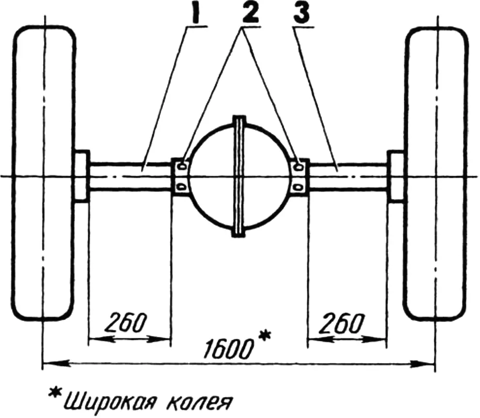
1, 3 — shortened axle-shaft housings; 2 — housing fastening bolts
The gearbox is connected to the rear axle by a driveshaft. The latter, as already noted, is from a ZIL-157 truck. Its modification amounted to cutting the axle shafts and their housings (“sleeves”). I fully dismantled the rear axle, cut off the rivets on the housing, pressed the sleeves out of it, shortened them on a lathe and pressed them back into the housing. I inserted bolts instead of rivets.
I cut the flanges off the axle shafts and drilled axial holes in them to the axle-shaft diameter. I shortened the shafts by the same length as the housings, fitted the flanges onto the remaining stubs and welded them around the contour. Then I carefully assembled the axle.
It should be added that the tractor’s rear wheel track is adjustable: if the wheels are swapped while keeping their direction of rotation, the track can be made narrow (for plowing) or wide (for transport work).
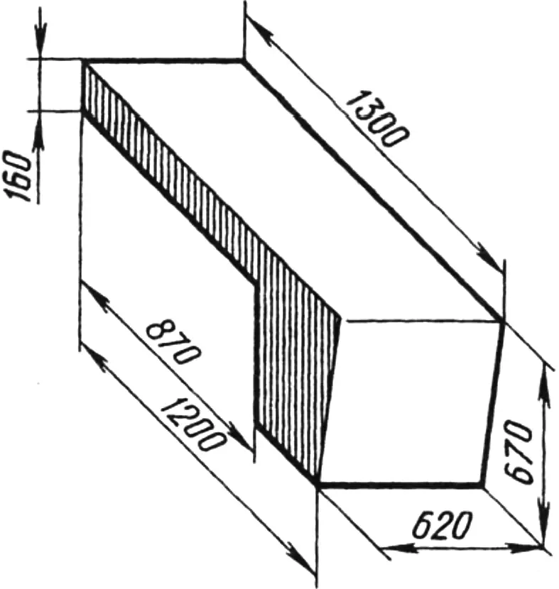
I made the engine hood from 1.6 mm sheet steel. The muffler is homemade as well, from stainless steel.
The machine has pneumatic brakes. They are very convenient and, most importantly, reliable.
The tractor turned out compact and maneuverable, with light steering and a soft ride (thanks to the springs).
The tractor can be hitched to virtually any agricultural implements, including homemade ones: a three-bottom plow (bottoms from No. 7 horse-drawn plows) and a cultivator, as well as a cargo trailer. The machine has no power take-off, it is true. But that does not bother me, because a GMSh-50 hydraulic motor runs quite adequately from the onboard hydraulic system, and a mower or circular saw can easily be attached to it.
I also considered how to mount a mini-excavator attachment on the tractor. That would require locking the rear-axle differential (the ZIL axle does not have it). It would seem one could fit a GAZ unit, for example from a GAZ-66, but then one would have to give up pneumatic brakes. So for now I am still thinking it over.
I have been operating the tractor for more than three years and am very pleased with it. It is liked not only by me and my fellow villagers. Our yard is a dozen meters from the busy Kyiv–Mykolaiv highway. Half of Ukraine, I dare say, has already driven past our yard where my favorite stands. People often stop and ask to see the machine or even to buy it. But I am in no hurry to part with my second creation. Perhaps later, when a third one appears…
Meanwhile I am developing a project for an all-wheel-drive tractor with an articulating frame like the T-150K, self-locking axles, a powerful hydromechanical gearbox, pneumatic brakes and a pneumatically actuated clutch. I hope that in time I will be able to realize this dream as well.
The author thanks his friend Yu. Melnyk for help in building the tractor.
Tractor specifications
Length (with implement hitch), m … 3940
Width, m … 1900
Height, m … 2350
Mass, kg … 2750
Maximum speed, km/h … 65
Minimum working speed, km/h … 5
Engine, model … D-144
Engine power, hp … 50
“Modelist-Konstruktor” No. 1’2001, A. BUDKO, Oleksandrivka, Kirovohrad Region
Recommend to read
 HERRINGBONE TURN AROUND!
Seven years in our school, works flawlessly simple turntable for Christmas trees; she turns the forest beauty, switch her colorful garlands; it can be used as a kind of bracket for the... OUT OF THE WOODS – IN THE KITCHEN
Quickly VI carefully cut the trophies mushrooms for drying or hot, you can use eggs or slicers.
