The trikes of the period was characterized by a large variety of schemes and layouts, bold the search of optimal technical solutions. In 1981 and 1983, such decisions were mostly found, followed by a boom in the development of these aircraft (LA).
But, before talking about the advantages and disadvantages of the schemes and the configurations of trikes, it is necessary to define what is meant by the term “trike”.
According to the existing international classification to ultralight aircraft are powerless LA weight 60 kg and powered aircraft weighing no more than 150 kg and a wing area not less than 10 m2 . These definitions taken in 1981 of the International aeronautical Federation for the purpose of registration records. Among non-motorized ULTRALIGHTS the most widely gliders. The definition of a glider, more fully taking into account the peculiarities of its design, the A. P. Klimenko.
According to this definition a glider is called ultralight aircraft, the aerodynamic bearing surface which is formed under the influence of flow on elastic medium “panel — frame” and can be controlled by moving the center of mass relative to the wing.
Motor development of ultralight aircraft, or, as they call them, ultra-light aircraft (SLS), goes in two directions: SLS, which are controlled by aerodynamic control surfaces (elevators and rudder, spoilers, ailerons), and SLS with balance control — trikes.
The essential feature of the latter is the power plant. In this regard, the definition of the glider can be fully transferred onto the trike with the addition of the definition of “motor”.
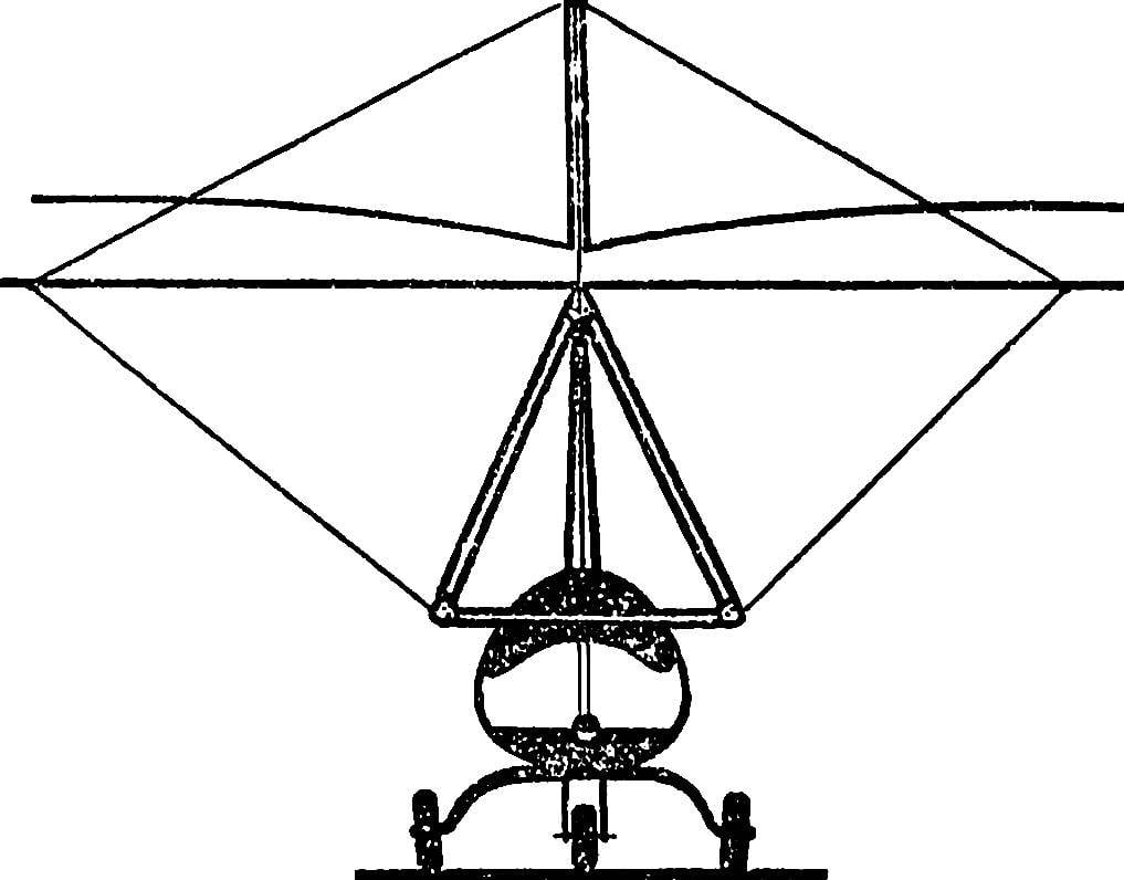
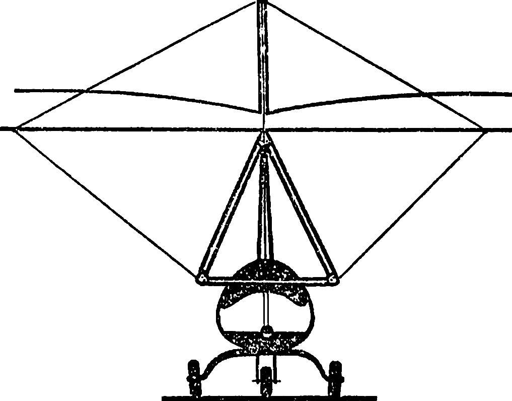
Figure 1 shows the basic scheme and layout trikes encountered at all stages of their development. The first group consists of MD, starting at the expense of running the pilot. The advantages of the devices of this group are low mass designs, the ability to set them on a low-power motors, to use to start uneven grounds.
Fig. 1. The layout scheme of trikes:
1 — with the engine on the back of a pilot 2 — with the engine under the wing, 3 — with the engine on the mast, 4 — with two engines on the wing or struts, 5 — with the engine on the trike, 6 — with engines on the wing or struts, 7 — with the engine on the fuselage, 8 — with two or more motors on the trike.
However, they cannot be applied for transport of a payload, performing a start the share of the pilot falls high physical activity; safety of flight lower than that of MD of the second group. Analysis of accidents in gliders shows that the overwhelming majority of serious injuries occur when a blow to the head or chest on the ground. The fact that the pilot of the trike (as well as sports apparatus) are not fixed rigidly relative to the structure, and is in a soft suspension system, allowing a pendulum movement relative to the wing. During the stall, which are possible during flights near the ground at low speed, the trike will collide with earth, when its trajectory is steeply sloping; in such a situation, the body of the pilot tilted forward, which increases the likelihood of unpleasant consequences. The single most effective method of self-defense used by hang-gliders — at any price to meet the ground with your feet.
A characteristic feature of trikes the second group is the chassis — the wheeled or float (when starting from the water). These devices are capable of carrying a payload, takeoff and landing on them is relatively simple, and the level of safety higher than in the MD of the first group. The latter is due to the fact that the pilots shielded power elements of a design and in most cases rigidly fixed with seat belts.
The trikes of the first group have the same application as the gliders. Their layout differ mainly in the location of the engines. The layout of Amateur spacecraft # 1 with engine at the back of the pilot is extremely rare. It is the least safe, the trip to MD this requires the pilot attention and tension at the start and moreover characterized by an extremely low level of comfort.
One variation of this layout is the machine with a hard suspension system of the pilot, to which is attached the engine.
Layout No. 3 with the motor located on the mast of the wing, used in the initial stage of designing trikes. The main drawback of the scheme lies in the fact that the line of action of the thrust was located significantly above the center of mass and suspension point of the pilot. As a result, the change of the thrust force greatly affects the value of the longitudinal moment and, consequently, longitudinal stability. In some modes, these devices showed a tendency to loss of longitudinal stability and controllability, and in the practice of their flight operations were “tumbling”.
Layout # 4 engines on the struts or on the wing also not received wide acceptance due to the complicated compared to other trikes in this group design, in addition, these CBMs were less easy to operate. Note that twin-engine aircraft has some advantage over single-engine only in cases where it can be balanced and continue the flight with one engine running. The option of balance when one engine is practically impossible.
The most popular the first group of MD was the layout of the No. 2.
The power plant of this trike consists of motor, long hollow rod connecting the engine with the bearing of the propeller drive shaft and the propeller. Design ensures quick installation of the power plant on the wing. In addition, the screw located behind and away from the pilot, increasing comfort and safety. Devices of this type are available commercially abroad.
Among ultra-light chassis, the most widespread layout No. 5. The trike (suspension system) attached to the wing via a hinge having at least two degrees of freedom in angular motion. Powerplant, the pilot’s seat, chassis, equipment, and other items attached to the trike. These trikes are easy to operate, not complicated in design that allows you to quickly disassemble and reassemble them to replace the wing. They are more comfortable, and managed in the same way as sports gliders. Trike adapted for the carriage of goods and passengers. If you remove the wing it can serve as a ground vehicle.
Found among Amateur ultra-light and the layout of No. 6. Its advantage — low weight; disadvantages — the inability to control pitch and roll in the run-up and run.
In the first stage of the development of trikes developed the scheme with the balance control for one or two channels and with the wind for the rest (layout No. 7). In the future, however, proved to be sufficiently effective aerodynamic control at such low speeds may be only when using control surfaces of large area.
It should be noted that control through flight surfaces led to more complex structure and increase in weight of the apparatus. At the same time, operation of the MD layout No. 5 revealed sufficient efficacy of the balance control. This is why the use of a mixed control pretty quickly refused.
Layout # 8 and # 5 are similar and differ only in the number engines. Apparatus with two-engined trucks built at present only experimental. Some advantage of MD over other such “dvuhnitochnyj” is the ability to balance and continue flying with one engine.
The greatest interest from the point of view of practical application of the present MD of the layout of No. 5. Compared to other ultralight aircraft they are most simple and cheap, have a good operating adaptability and maintainability. In particular, the trike is about two times cheaper than the schematic ultralight aircraft with aerodynamic steering. It should be noted that the wing this MD is not fundamentally different from the wing of a conventional machine, the main difference with a reinforced frame.
Fig. 2. Scheme mototalk:
1 — cable, 2 — panel, 3 — truss, 4 — beam.
Much more constructive diversity in mototelecom. Figure 2 shows four types of the currently used trucks. The cable contains a minimal number of rods, raskalennyj mechanical rope stretch marks. It is popular due to the minimal weight, good performance and maintainability. The trike, made according to the cabling diagram, quick and easy to fold and take up little space during storage. The disadvantage is less compared to other schemes durability and reliability.
Of great interest are the trike panel scheme. They contain the minimum number of power components — rods, used to make flat panels, connecting then with each other, and only slightly heavier cable with approximately equal production and maintainability. The complexity of manufacturing mototelecom cable and panel schemes are the same.
The trike panel schemes have high strength and reliability. They are able to take shock loads caused during an emergency landing, provide the pilot with greater safety, less likely to break. Most often they design for ultra-light aircraft, which is expected to operate in harsh conditions from unprepared runways.
Truss the trike consists, usually, of two or more space trusses. The scheme is not widely used, although in comparison with other such truck is stronger, and the failure of one of the power elements does not disturb the efficiency of the system. The disadvantages are the large number of connecting elements, the complexity of Assembly and disassembly. And last — this scheme does not provide collapsibility.
The trike beam design is a complex hollow I-beam running, often fiberglass, upholstery. It is the most comfortable, has less aerodynamic drag. On the other hand, make it much more complicated than truck other circuits. Moreover, it is not additive, which complicates the transport.
Very often, by the way, there are also “hybrids” that include elements of different schemes.
A classic example of MD with beam trike is T-4, developed by specialists of OKB of O. K. Antonova. Its aerodynamic framework — sports hang-glider of the same company “Slavutich-Sport” with reinforced frame. Trike fiberglass, is laminated on the matrix. In combination with the suspension system, wing, engine and chassis mounted embedded metal elements. T-4 is designed to perform training flights and participation in competitions. This apparatus is repeatedly used to perform demonstration flights for sporting holidays and competitions, parades, and ALS.
Fig. 3. Trike T-4 OKB O. K. Antonov — classical apparatus with beam trike.
The double glider MAI-2, created under the leadership of the student-graduate A. Hare, applied panel trike. This apparatus was demonstrated at the all-Union review-competition, the SLA-85, which were highly appreciated by experts and took first place in its class. His only flaw: unreliable propulsion system based on the engine “FS—400”.
Fig. 4. Double glider MAI-2 designs A. Hare with panel trike.
One of the most successful designs of cable truck serial French trikes type “Space”. This unit is easy to operate, easy to disassemble and quickly installed. Bring it from the transport position (blades in the package dimensions 4500X350 mm, folded trike) working in 10 mins, and do it for one person.
Fig. 5. Serial French office of the “Space” with the cable a trike.
Almost all the terminals in the Golf cart made of tubes with Ø 53 mm with a wall thickness of 1.3 mm, with longitudinal and vertical rods are reinforced for the entire length of the tubes 50X1,3 mm, laid in. In addition, the vertical rod has a safety rope stretching, which on the one hand is fixed to the node elements of the suspension, and the other to the bolt fixing vertical and longitudinal rods.
Trial operation MD “Cosmos” has shown that it requires a very “delicate” relationship and not designed for a rough landing, to avoid them not even highly skilled pilots.
Fig. 6. Double pilot trikes from the trike truss “Search-03”, created in SKB MIIGA.
When creating an experimental twin-engine trike “Search-03” we chose the trike truss diagram. It is a two module — upper, made of pipe Ø 34 mm (wall thickness 1.5 mm) and the bottom of the pipes Ø 36 mm (wall thickness 2.5 mm). “Search-03” built in SKB Moscow Institute of engineers of civil aviation (MIIGA) and is designed to study the characteristics of piloting and research functionality trikes of this scheme.
It should be noted that most of the design and flight test work conducted in the SKB of the Institute, has allowed to identify the most successful scheme of trikes, their advantages and disadvantages. We think the readers of “M-K” it will be interesting to get acquainted with one of our machines. Read more about it — in one of the following numbers.
The main characteristics of trikes
I. NIKITIN, head of SKB MIIGA
Recommend to read RAIN CLOSES THE WINDOW Darkened sky, the wind rustled the leaves, and now the first drops were informed about the start of the rain. And then you remember: "But at home I have the window open!" And as it... SUPPORT-UNIVERSAL If you saw a Board, as shown in the picture, you get four blanks to build universal support for any rack — for example, the hanger or Christmas tree. Assembly can be done with nails or screws. Scroll back to top
 Hang gliding in the 70-ies experiencing a period of rapid development in a short time became a popular sport. The secret of success is primarily due to the simplicity of design and unique performance characteristics of the aircraft. Less than a decade it took to hang gliding to become an Olympic sport. And the desire of athletes to expand the capabilities of the glider due to the start with a flat terrain and climb in the absence of ascending currents has led to that began to appear on the gliders equipped with engines.