Since the front and rear endings of the body are surfaces of double curvature, they were collected on the rivets of the pre-cut elements. Each pre-attached to the dome-shaped form. The roof is also made convex, but the whole curvature of the surface is small. The side trim went duralumin with a thickness of 0.5 mm To increase the stiffness of sidewalls reinforced by ribs. “Skeleton” sheathed outside duralumin with a thickness of 1 mm, and the inside — 0.5 mm. are also composed of frames and stringers.
It should be noted that the seat as such do not exist. They are replaced by niches in the floor that fit the seat cushions from foam, covered with leatherette. At the front the back is attached to the brackets, allowing it to be tipped forward for easy passenger boarding. The back is also foam, with a skinny leatherette.
In areas of high body stiffness riveted pads, which privernuty mounting brackets pipe suspension. The horizontal surface of the engine compartment, the quantum well enhanced 3-mm overlay of D16T.
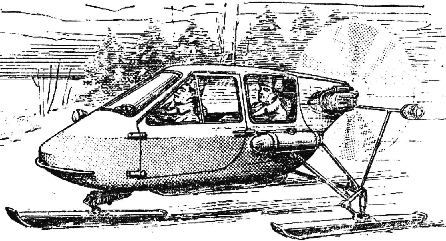
Fig. 1. General view of the snowmobile:
1 — screw, 2 — hood, 3 — engine, 4 — body, 5 — tank, 6 — door lock-knob, 7 — door, 8 — windscreen 9 — front ski, 10 light, 11 — wheel, 12 — seat 13 — suspension the front of the ski, the 14 — rear ski, a 15 — suspension rear ski 16 — fencing screws with washers and tail lights.
Fig. 2. Body structure:
1 — casing, 2 — transverse bulkhead, 3 longitudinal bulkhead, 4 — side stiffeners, 5 — niche seats, 6 — cabin floor (section enlarged)
Fig. 3. The rear ski (cross-section):
1 — sole 2 — cutting, 3 — box case of skiing, the 4 — frame case, 5 — bracket, 6 — finger, 7 — absorber, 8 — bushing of the control arm, 9 — longitudinal bulkhead with the reinforcing plate.
Fig. 4. The steering mechanism and suspension front ski:
1 — ski (sectional), 2 — bracket, 3 — rubber stopper 4 — traverse 5 — spring pull, b — body frame, 7 — longitudinal bulkhead of the body, 8 — base, 9 — steering arm, 10 — rope 11 — wheel, 12 — bracket, 13 — steering shaft, 14 — reel, 15 — needle bearing (No. 942-25), 16 — shaft, 17 — Cup, 18 — frame body, 19 — bearing (no. 7207), 20 — rod 21 — the lever.
Organic glass 3 mm thick.
The body is painted with two coats of enamel ML-197, deposited on a layer of primer GF-020. Color combo: bottom orange, top blue. The weight of the body with glazing 35 kg.
Rotor installation includes motor, gear and variable-pitch propeller. Using the gear, we were guided by the fact that it allows more advantageous to use the power of the engine, shifting the frequency of rotation of the screw in the area up to 2 thousand rpm (max). The result is higher efficiency than a smaller propeller operating at high speeds. The possibility to change the angles of the blades during the movement attracted us because it allows to change the traction until the reverse and implement aerodynamic drag.
The design of the gearbox and gear change step is shown in figure 6. They were designed under the existing engine “Zundapp” (25 HP). So later, when using the motor M-63 Ural (28 HP) for mounting the gearbox had to make the transition flange. With the use of the engine M-63 total weight of the power unit has decreased by 10 kg to 65 kg.
The reducer consists of a body and extension. In the housing mounted gear, and the extension serves to support the shaft of the screw. The case is welded steel. It is formed by the flange and welded to it a reinforcing ring of sheet steel with a thickness of 2 mm. Inside welded socket for bearings with ribs. The case is also ribbed. After welding it was subjected to stress relief heat treatment. Extension cable made of the same technology. Used cylindrical gear, spur; number of teeth Z1= 32, Z2 = 60, the module is 1.75, crown’s width b = 25. Gear selected ready, rework is minimized. They planted on the ramparts of parallel keys. Shafts are made of steel 30KHGSA. To facilitate they are made hollow, termoobrabotannyj to a hardness of 42… 45 units rotate through the angular contact ball bearings, preload which is adjustable by selecting the thickness of compensators. The torque from the engine is transmitted to the input shaft through the elastic rubber coupling. The reducer is filled with 100 ml of gear oil.
The basis of the mechanism of change step is based on the principle, widely used in aviation. The only difference in the drive: aviation hydraulic usually, we have a mechanical. The mechanism is mounted in the propeller hub and operates as follows.
Each blade in the butt portion has a shank consisting of a flange and a threaded part (M20X1,5). The shank is screwed into the shaft bushing also having a flange. After installing the blade flanges are tightened by a clamp. Thus, the blade is rigidly connected with the shaft bushing and its angular position will correspond to the angular position of the shaft. The latter is driven in rotation by a leash, which is connected via end key. The leash receives the rotation of the plug; she, along with the stem can move progressively relative to the axis of the screw shaft. Stock through a system of levers and rods connected with the pitch control knob, located to the right of the driver. It has 10 fixed position, allowing you to change the traction force depending on the road conditions. Moving “by itself”, we are forcing the plug to move to the left (as shown); at its extreme position, the blade will turn on big step. Taking the handle “on itself”, we’re moving the blade in small steps and then to reverse; its average position corresponds to zero traction. The nominal stroke is 30 mm, it corresponds to the rotation of the blade 60°. All the details of the mechanism are made of steel 30KHGSA. The centrifugal force from the blades is taken by the thrust bearing.
The purpose of the centrifugal loads is as follows. The rotation of the propeller for a cargo operates the centrifugal force, creating a moment, turning the blade upward step. This effect creates interference in the control circuit and reduces stress on the handle. As goods used steel balls Ø25 mm.
The figure shows the blade, its geometry and major dimensions. The procedure of manufacturing of each of them is.
From mm plywood cut 20 strips size mm. 135X600 Blanks are glued together in the package with epoxy resin in a special fixture, which provides the package with specified twist (25°) and generates the necessary compression. After that, the blade is processed according to the contour and the convex side of the profile; the flat side is obtained ready after gluing. The correctness of the profile is controlled by the templates. Then the blade is sanded, puttied and painted. The geometry of the blades, their size and weight must be strictly the same. Their parameters are selected on the basis of the analysis of existing designs and literature.
Speed characteristics of snowmobiles largely determines the suspension, especially skiing. They must be not only strong and rigid but also light, have a good slide, to be convenient in fabrication.
Fig. 5. Diagram of wire rope steering:
1 — steering arm 2 — unit, 3 — wire, 4 — drum steering shaft.
Fig. 6. The mechanism of change of the screw pitch and gearbox:
1 — housing grommet screw, 2 — leash, 3 — cap sleeve, 4 — ball bearing (No. 36101Е3), 5 — clamping screw, 6 — needle bearing (No. 942-25), 7 — thrust bearing (No. 8205), 8 — a centrifugal cargo 9 — clamp 10 — shank blade, 11 — blade, 12 — screw shaft, 13 — bearing (No. 36207), 14 — spacer-extender, 15 housing, 16 — driven gear (Z =60), 17 — bearing (No. 36205), 18 — drive rod pitch control, 19 — transition flange, 20 — engine, 21, the flywheel 22, the clutch housing 23 of the finger 24 is a rubber coupling, 25 — input shaft, 26 — leading gear (Z = 32), 27 — bearing (No. 36203), 28 — plug mechanism to change the pitch (section a—a and a is reduced).
Our skis quite satisfy the first four requirements, although several less technological than I would like: some rivets out on each about 700 pieces. The design of each ski carrier has the shape of a closed box with trapezoidal section and formed on the bottom sole and the top and sides of the bent box lining. Inside along the length are two longitudinal partitions. All items with the exception of the soles and guides undercuts made of sheet duralumin brand D16T.
The sequence of Assembly. First longitudinal bulkhead with riveted corners and reinforcing plates.
The latter is made of D16T sheet thickness of 3 mm, have a length of 450 mm and located in the middle of the ski (in partitions and linings for ease made holes with a diameter of from 25 to 50 mm). Then between partitions vkladyvayasj frames (6 PCs.). The received frame is superimposed on the sole and priklepyvayut to her together with guide pruning. The sole material is stainless steel with thickness of 0.5 mm. (Sheet polyethylene as a material for sliding surfaces were first tested on the sled, he quickly wore out, particularly when driving on icy roads.) The Assembly of the ski ends with priklepyvayut top covering four main joints: the lower two sole and two upper corners with longitudinal partitions. For riveting the upper seams in box-shaped covering made a series of holes Ø85 mm, through them, summed up support. After riveting the top of the ski to seal the papered leatherette. The weight of the front of the ski was 5.5 kg rear, which is longer — at 6.5 kg.
The two rear skis are suspended on longitudinal rocking levers to the farm, formed by three tubes, are attached to the body at three points. Arm pressed to textolite bushings in which they rotate relative to the finger. The shock absorber of a motorcycle “Java” with one end attached to the lever, and the other to the farm. Farm power and arms are made of hromansilevyh pipes. For leverage use a pipe of elliptical cross-section with the greater axis of the ellipse is 45 mm.
Device front suspension and steering.
Similarly, the rear, the front skis suspended on longitudinal rocking lever welded structure. With a lever connected through a linkage system of the seven tension spring, taken from the rear brakes of the car “the Zhiguli”. Suspension stroke 100 mm. For its limitations is a rubber buffer.
The arm swinging on the traverse, which, together with the shaft can be rotated from steering gear. The latter consists of steering wheel (car type) steering shaft and the cable system. The cable is made in the following way: in the bowl planted on the steering shaft, drilled diametrically through hole Ø3 mm. is passed Through the rope so as to make two equal length branches. The rope fastened to the drum by a retainer (not shown). Each branch makes around the drum two turns in opposite directions, is passed through the blocks and is closed up on the lever. The degree of pressing of a cable is governed by a special device. The bracket to the instrument panel. The steering wheel makes a half-twist that corresponds to the rotation of the skis 60°.
Additional equipment include the following. Outboard fuel tanks located on each side of the snowmobile, welded, galvanised iron, have an internal baffle. Fairings are from foam. The tanks communicate with each other-and gasoline-proof rubber hose, filler neck is in the left of them.
On the dashboard are installed: airspeed indicator, tachometer, toggle switch and pilot light ignition.
Speed indicator — aircraft type, tachometer self-efficient, electronic. Electrical equipment includes a battery ignition system and lighting (headlight, Parking lights). The engine starts only from the screw.
The snowmobiles were manufactured in 10 months, including design. They were tested on snow with different hardness and under different load. Even fully loaded the sleigh is very easy walking on Packed snow if the air temperature and — 5°, — 15°. Speed may exceed 100 km/h On snow idle field speed was 30 km/h (when driving without a passenger). It was determined by the speedometer of a car traveling parallel to the highway. Movement over the snow, perhaps one of the most difficult modes for snowmobiles: the engine has to work almost on a limit, therefore, the power gain of 10-12 HP required In this regard at the present time we designed and started to build a radial two-stroke engine designed specifically for snowmobiles. Conversation about it may be yet to come, after the test.
Recommend to read IS STRUTS – STRUTS The times when concern about human health in our country was a matter of state, has sunk into Oblivion. Quality free health care now depends on the good faith of the doctor, and paid... MYCHITE LOUDER Among the many toys in the electronics, is able to mimic the sounds of animals, is very amusing. For example, a toy cow, imitating mooing, or a pig, saying, "let's Go home, I'm hungry!"... 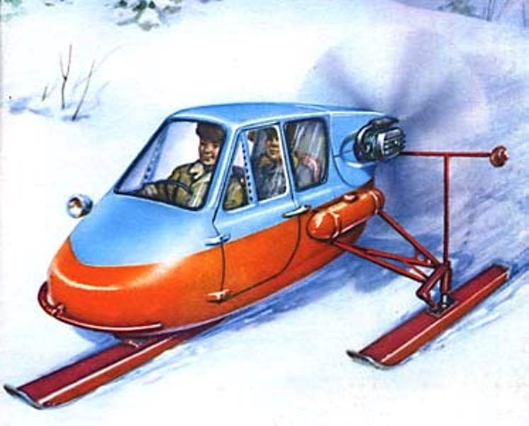
 “They are not afraid of obstacles!” this is the motto of our magazine a few years ago began to publish descriptions of the designs of a homemade all-terrain of micro-technology, immediately attracted the attention and then the affection of readers. During this time in our regular sections “Public CB “M-K”, “Create, invent, try!”, “Competition of ideas” we talked about many unusual and original machines: all kinds of snowmobiles and amphibians, multiwheel and tracked micro cars, motonartah, sports-dirt cars buggy, snowmobile. In this opening year we introduce another interesting development — snowmobile “Triumph”, created by the designers-lovers from Saratov O. YAKOVLEV and V. SIDE.