 (The end. Beginning in № 12, 1974)
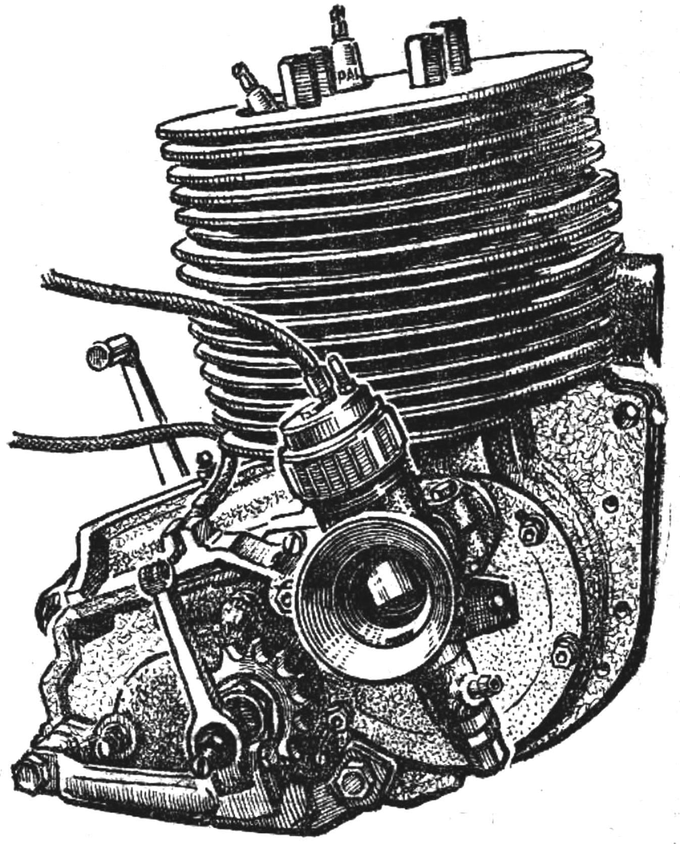
In the previous issue of master of automobile sports of the USSR M. Todorov spoke about how we need to begin work on the boost engine, providing installation disk of the spool. The reader is a continuation of this article.
The PISTON (Fig. 1) machined from heat-resistant aluminum alloy AK4-1. Weight — 170 g. After preliminary machining, the workpiece is subjected to hardening (aged for hours at 525-540°, then lowered into warm water). Followed by aging for 10 hours at 180-190°.
When final machining is necessary to ensure the perpendicularity of the axes of the holes of the piston pin and the piston. The clearance between the piston skirt and the cylinder wall after turning 0,07 mm.
The outer cylindrical surface of the piston need to attach this form to the cross section turned out an ellipse. The major axis it is perpendicular to the axis of bosses and equal to the diameter of the piston. The minor axis of the ellipse extends along the axis of the bosses; it is smaller than the piston diameter 0.1—0.15 mm.
To reduce nagaroobrazovanie the piston head is polished. The piston pin has a floating fit, and an axial displacement prevent his retaining rings similar to the approach used in serial engines. The depth of the grooves in these rings should be 0.6÷0.7 diameter of the wire from which made the ring.
Piston rings are made of steel 65G, tempered to a hardness of HRc = 45÷50 and covered with porous chromium. The upper ring is L-shaped, bottom — flat, height 1.2 mm.
The CYLINDER consists of an aluminum shirt and pressed into her cast-iron casings. Shirt is made of oplav D16 according to figure 2 (overflow and outlet channels not shown). The sleeve is machined from alloy cast iron centrifugal casting with an austenitic structure. The container size after the turning process is shown in figure 3. The location of Windows on the internal surface of the cylinder shown in the scan (Fig. 4).
After the final production of Windows in the sleeve and the bypass channels in the shirt sleeve pressed into the shirt with interference 0,11—0,13 mm. the Front of this shirt is heated to 350°; degree of heating is controlled by the darkening of the grains of sugar placed on the heated surface of the part. The shirt is inserted into a cold liner and blend the bypass Windows with respective channels of the shirt, and then the cylinder is allowed to cool.
From the discharge opening edges of the shirt frezeruyutsya to obtain a site sufficient for the flange fastening the exhaust pipe. Especially should not be done, as this reduces the area of the fins and reduces cooling of the most heat-stressed parts of the cylinder. The outlet tube is fastened to the shirt with four short studs.
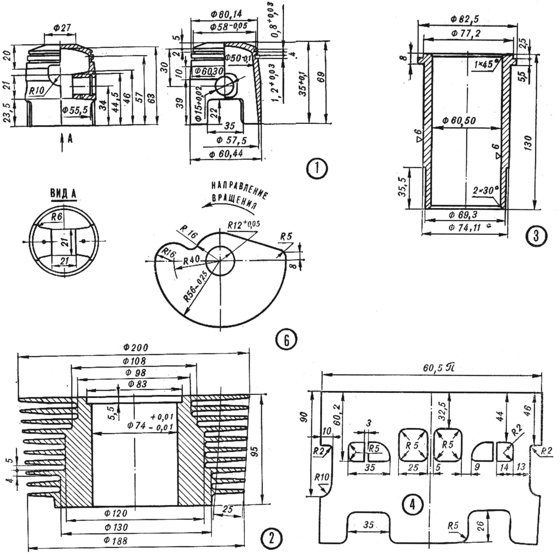
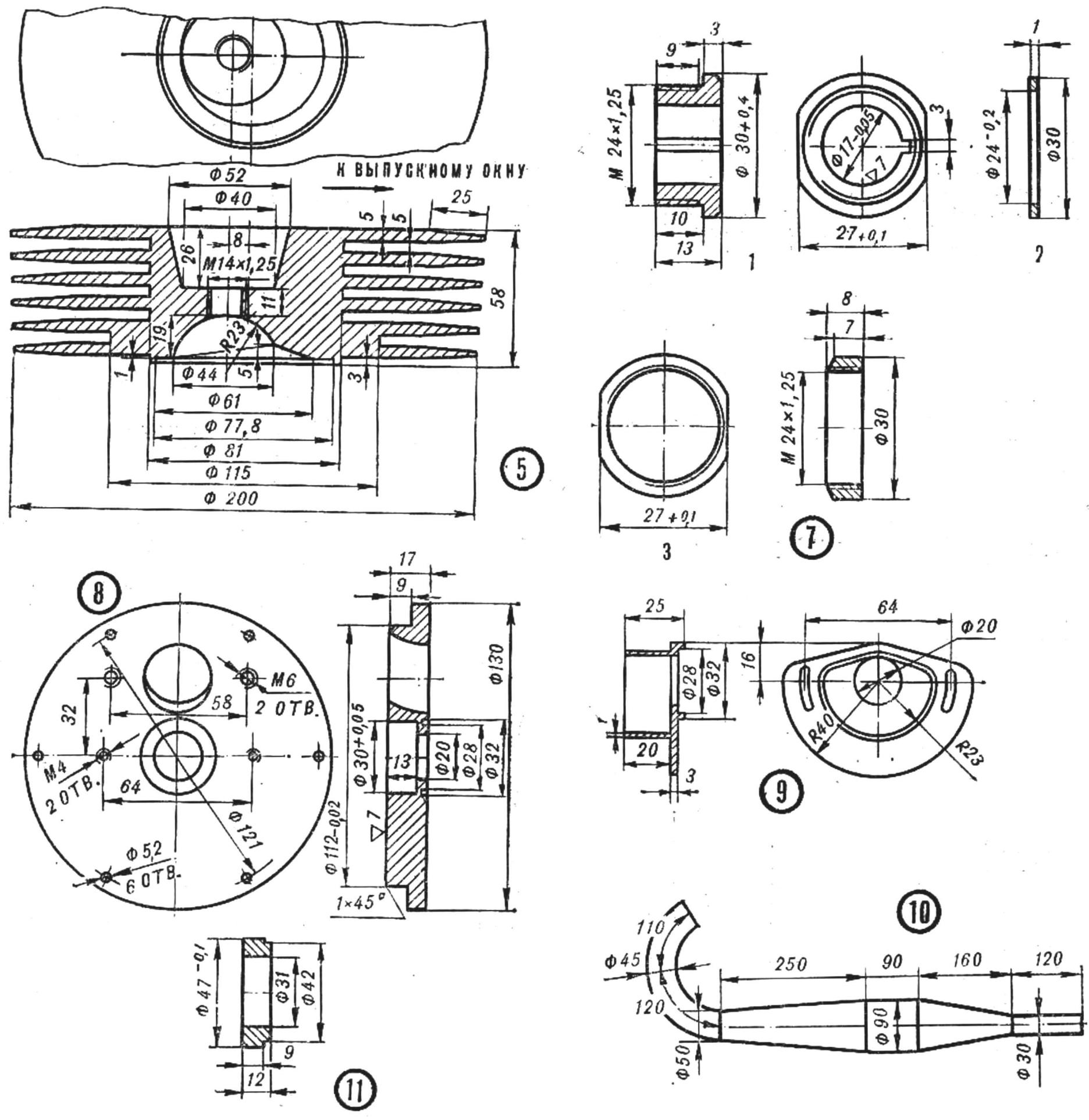
Fig. 1. Piston.
Fig. 2. Shirt cylinder.
Fig. 3. The cylinder liner.
Fig. 4. Scan cylinder.
Fig. 5. Cylinder head.
Fig. 6. Spool.
Fig. 7. Mounting parts of the valve:
1 —nut; 2 — washer; 3 — bushing.
Fig. 8. Cover Zolotnik camera.
Fig. 9. The body of the breaker.
Fig. 10. Exhaust pipe with resonator.
Fig. 11. Spacer.
An exhaust channel in the shirt is milled on-site, and the need to ensure a smooth transition from rectangular exhaust window to the round cross section of the exhaust pipe.
The inner surface of the cylinder is brought to the desired purity and size on a lathe with a sliding cylindrical cast-iron lapping. For the winter competition on the motor, a head, machined from alloy D16. according to figure 5. For the summer races required head with larger fins, such as motorcycle engine “Chezet-250”. The combustion chamber this head should be brewed with aluminium using argon-arc welding, and then machined a new one (see Fig. 5). It is also necessary to drill into the head of the new holes for the pins and adjust the length of the holes for the candles. Between the cylinder head and the flange of the sleeve is mounted an annular strip of soft aluminum with a thickness of 0.5 mm.
INTAKE SYSTEM OF THE WORKING MIXTURE. A flat disc valve (Fig. 6) is driven in rotation from the right axle of the crankshaft. The spool is made from heat-treated sheet of steel 65G thickness of 0.5 mm and rigidly fixed to the hub (Fig, 7) with the nut. The sleeve is put on the end of the right axle and the crankshaft together with the disk can move freely along the axle under the influence of pressure fluctuations within the crank chamber. The amount of movement is limited by the clearance between the spool and the walls Zolotnik camera. From the corner of the offset bushing is fixed on the axle dowel.
The position of the disc valve relative to the crankshaft provides the next phase of the inlet of the working mixture: the opening of the inlet window 65° after BDC; the inlet end of the closing window of 72° after TDC; intake — 187°.
In the lid Zolotnik camera (Fig. 8) set right side oil seal crankshaft of the engine “Rising”.
IGNITION SYSTEM battery. It uses ignition coil motorcycle type 6 In and sealed battery 5КНГ-10. To the right trunnion of the crankshaft bolt attached to the Cam of the circuit breaker. Outside cover Zolotnik camera is mounted the housing of the circuit breaker (Fig. 9), and as the latter is used in the chopper of the scooter “Tula 200”, base plate height of the breaker is cut to the size of the cavity of the housing.
Spring breaker is strengthened. His body is centered on the recess cover zolotnikova camera and attaches to it two short screws M4. By turning the housing of the circuit breaker when slightly loosened the bolts to set the desired time of ignition. The capacitor is placed near the ignition coil.
The exhaust SYSTEM consists of exhaust gases from the exhaust pipe and resonator (Fig. 10). Construction all-welded, checked for leaks. The resonator is made of mild steel with thickness 0,8 mm. the Pipe is connected with the exhaust pipe of the cylinder by means of labyrinth seals. Shown on figure 10, the geometric dimensions are selected in the result of bench tuning of the exhaust system for maximum power, that is, to use the engine for track competitions, in particular for racing on ice. For maximum acceleration, it is necessary in the racing circuit, the length of the resonator cones it is necessary to slightly increase. The engine power will also decrease.
ENGINE ASSEMBLY. All parts before Assembly should be washed in kerosene, carefully subjected to lapping: for complete removal of the abrasive powder.
In half of the crank camera zapressovyvajutsja bearings and left side oil seal is installed the crankshaft, which is with very thin washers centered to obtain equal gaps between the cheeks of the shaft and the walls of the crank chamber.
After installing the guide bushings of the two halves of the crank camera to cinch the bolts and then check the ease of rotation of the crankshaft.
The tightness of the crank chamber is provided by a strip of soft cardboard with thickness of 0,5 mm.
Then installed the piston, cylinder and head. The piston is put in a position of NMT on the right axle of the crankshaft is attached to the spool with a sleeve (Fig. 11). In the head of the Cam bolt breaker clay bonded to a circular disk with divisions of one degree, and against risks of 0° on the right half of the crank chamber are fixed needle. Turn the crankshaft clockwise, by 65°, it is necessary to set the spool in the sleeve at the beginning of opening the intake Windows. Without disturbing the position of the spool relative to the sleeve, Shine the bushing from the axle of the crankshaft and tighten the mounting nut of the valve, then install the bushing with a fixed spool in place and to verify that the crankshaft position (72° after TDC) the end of the spool closes the suction channel. If closing occurs earlier, to file the corresponding edge of the spool to the desired value. After the installation phase of the intake to remove the drive from the divisions and the needle, install the cover Zolotnik camera with branch pipe of the carburettor and breaker.
Engine transmission, clutch and gearbox are going in the same sequence as that of the production engine of the motorcycle “Voskhod”. In the Assembly process is checked for ease of rotation of the shafts of the gearbox, all gears, full engagement of the splines. At the end of the Assembly box is closed right-cover with pre-mounted to the secondary shaft.
Cover is centered by two guide bushings installed in rear mounting holes of the engine to the frame map, and is drawn to the left half of the crankcase with screws. On the cover is mounted to the lever cutoffs of coupling from the engine TO-175СК. Last set left crankcase cover, gearshift lever and pedal kick. In the case, the gearbox is filled with oil.
The assembled engine is mounted on a card or on the brake tester, connect the control cables, fuel pipe, ignition system. After the first start of the engine should be run at low speed with no load — about half an hour, and at a medium speed under load — several cycles of 10 min. it is necessary to take breaks for cooling and inspection of the engine.
The total time of running under load at moderate speed, sufficient for the running of all parts of the engine, is one hour. Thereafter, the engine can be tested on full load (on the stand or on the track). At the end of the tests, inspect the engine, check the tightness of all connections, repair leak oil and gas if she showed up, inspect the bore and piston — inspect for burrs and signs of increased friction (dark shiny spots on the piston).
Low carb in the summer working in a very dusty area. Therefore, in order to increase the durability of the engine in the summer should apply effective air filters. Winter racing on the ice of the sufficient installation of metal mesh with cell 6X6 mm, which protects the carburetor against ingress of large pieces of ice.
M. TODOROV, master of sports of the USSR
Recommend to read
 COMFORTABLE AND BEAUTIFUL
Now a for additional lighting over the kitchen counters satisfied with the lamp, hanging it is usually to the bottom of the shelves. However, the fluorescent lamp with fixture suspension... THE ATMOSPHERE IN THE CAR
Many motorists, especially the owners of domestic vehicles has experienced all the "charms" winter operation "beloved horses". Special "pleasure" — after frosty nights to bring to life...
