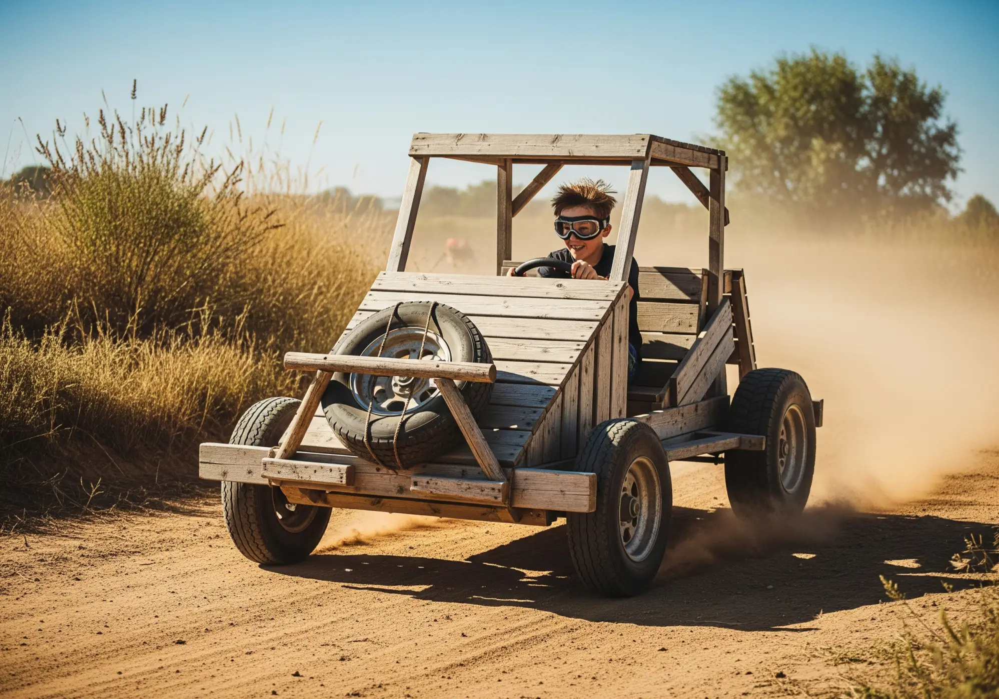
Several years ago, I made a small bicycle car for my sons (or, judging by its size or construction, it would be more accurate to call it a bicycle kart). The children liked the machine, and they, together with the neighbor kids, spent hours racing it on quiet streets.
I took as a model the design of a simple non-powered mini-car, a publication about which appeared in the magazine “Modelist-Konstruktor” No. 3 for 1977. It was in that year, while still in third grade, that I persuaded my father to subscribe to the magazine for me, the bound volumes of which I not only keep for all subsequent years, but still find much useful in them.
Now the sons have outgrown this machine, but the younger one often takes it out to the street, where among the children there are many who want to ride it. And he himself still doesn’t deny himself the pleasure of pedaling and steering the bicycle kart.
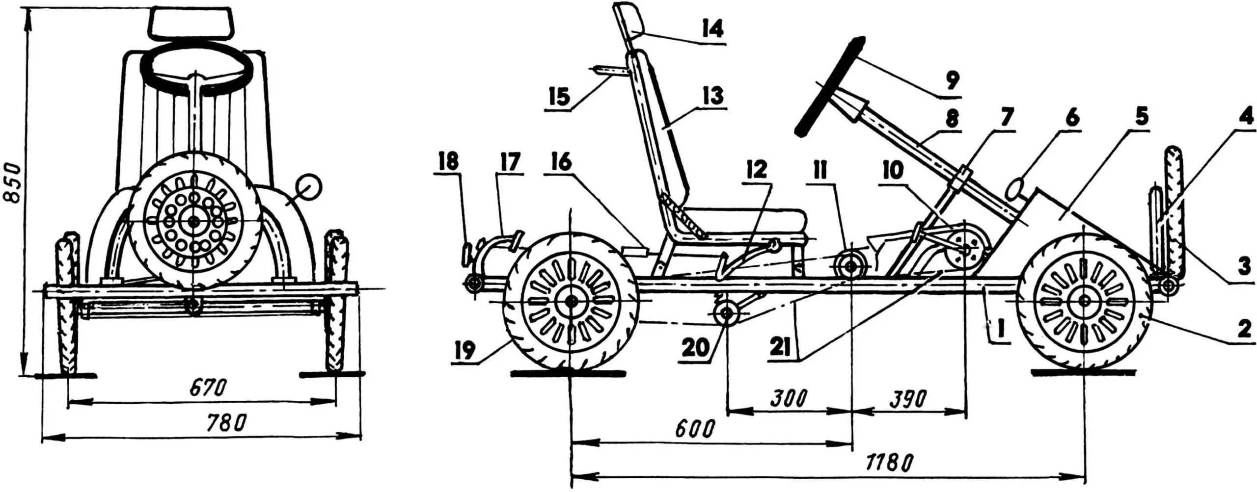
1 — frame; 2 — front wheel (drive from three-wheeled children’s bicycle, 2 pcs.); 3 — spare wheel (from children’s bicycle); 4 — stand and bracket for mounting spare wheel (bicycle tube and steel sheet s2); 5 — hood (duralumin, sheet s1); 6 — rearview mirror (motorcycle); 7 — steering shaft brace; 8 — steering shaft; 9 — steering wheel; 10 — pedal drive (from children’s bicycle); 11 — intermediate shaft with large and small sprockets; 12 — brake handle; 13 — seat (frame — from “Kolkhida” truck, plywood, foam, leatherette); 14 — headrest; 15 — handrail (tube Ø20); 16 — brake drive block and cable; 17 — brake lever with pad; 18 — reflector (4 pcs., automotive, front — white, rear — red); 19 — rear wheel (from children’s bicycle “Kosmos”, 2 pcs.); 20 — second-stage chain tension mechanism; 21 — drive chains (from children’s bicycles)
The bicycle car frame is welded mainly from steel thin-walled tubes of various diameters, taken from frames of bicycles that have served their purpose. Only the rear wheel axle and the front axle beam are made from plumbing (with thicker walls) half-inch tubes.
The front and rear cross members of the frame are also bumpers, so they, like the side members, are made from tubes of larger diameter than the other frame elements. The angular connections of the cross members with the side members are reinforced with gussets made of 2-mm steel sheet.
The pedal drive with sprocket, bottom bracket, and part of the frame was borrowed from an old children’s three-wheeled bicycle “Kosmos”. This unit was welded to the middle longitudinal insert of the frame.
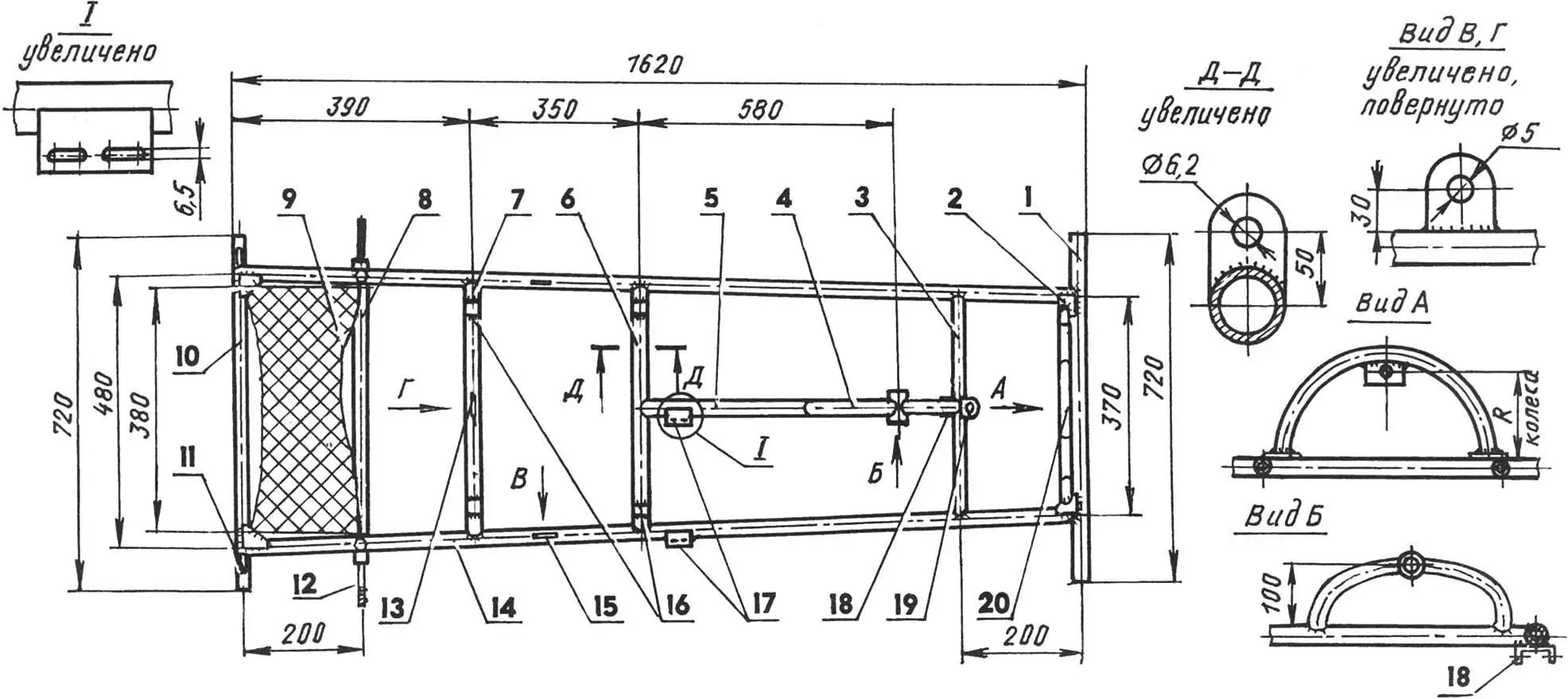
1 — front bumper; 2 — gusset (St3, sheet s3, 4 pcs.); 3 — front cross member; 4 — pedal drive subframe (from three-wheeled bicycle “Kosmos”); 5 — middle insert; 6 — middle cross member; 7 — rear cross member; 8 — rear axle beam (plumbing tube 1/2″); 9 — passenger platform (steel corrugated sheet s2); 10 — rear bumper; 11 — brake device bushing (plumbing tube 1/2″); 12 — rear wheel axle (St3, round 22, 2 pcs.); 13 — brake device bracket (sheet s3); 14 — side member (2 pcs.); 15 — brake device transverse cable mounting eye (St3, sheet s3, 2 pcs.); 16 — seat frame mounting brackets (channel No. 2.5, 4 pcs.); 17 — intermediate shaft support mounting brackets (St3, sheet s3); 18 — front beam suspension joint eye (channel No. 5.5); 19 — steering shaft support bracket (St3, sheet s3); 20 — spare wheel subframe and bracket
Since the pedal drive is installed along the machine’s axis, and there is only one drive wheel (rear right), I couldn’t do without an intermediate transmission. For it, I adapted sprockets — all from the same “Kosmos” bicycle. The large (20-tooth) sprocket is welded directly to the intermediate shaft. The other — the small sprocket (z = 16) of this transmission — is mounted on the intermediate shaft through a steel hub, to which it is welded, and the hub is secured to the shaft with a cotter pin. The plain bearings in which the intermediate shaft rotates were initially made from nylon, and when they wore out during operation — replaced with Teflon ones. The intermediate shaft support brackets are fastened with M6 bolts to plates welded to the frame with longitudinal slots. These longitudinal slots serve to tension the first-stage drive chain. The second-stage chain is tensioned using a Teflon roller mounted on a spring-loaded lever cut from a bicycle pedal crank. The drive wheel sprocket is also taken from an old children’s bicycle.
The front axle beam is made from a half-inch plumbing tube and made pivoting. Its connection to the frame is accomplished by means of only one hinge bracket in the middle part. Such axle suspension prevents not only one of the front steering wheels from lifting on uneven roads, but also, perhaps more importantly, — the drive rear wheel. One part of the hinge is a steel bushing with a Teflon plain bearing inside, welded to the axle beam. The second part is a bracket in the form of an eye; it is welded to the frame cross member. Both parts of the hinge (and therefore — the front beam and frame) are connected to each other by an M12 bolt-axle.
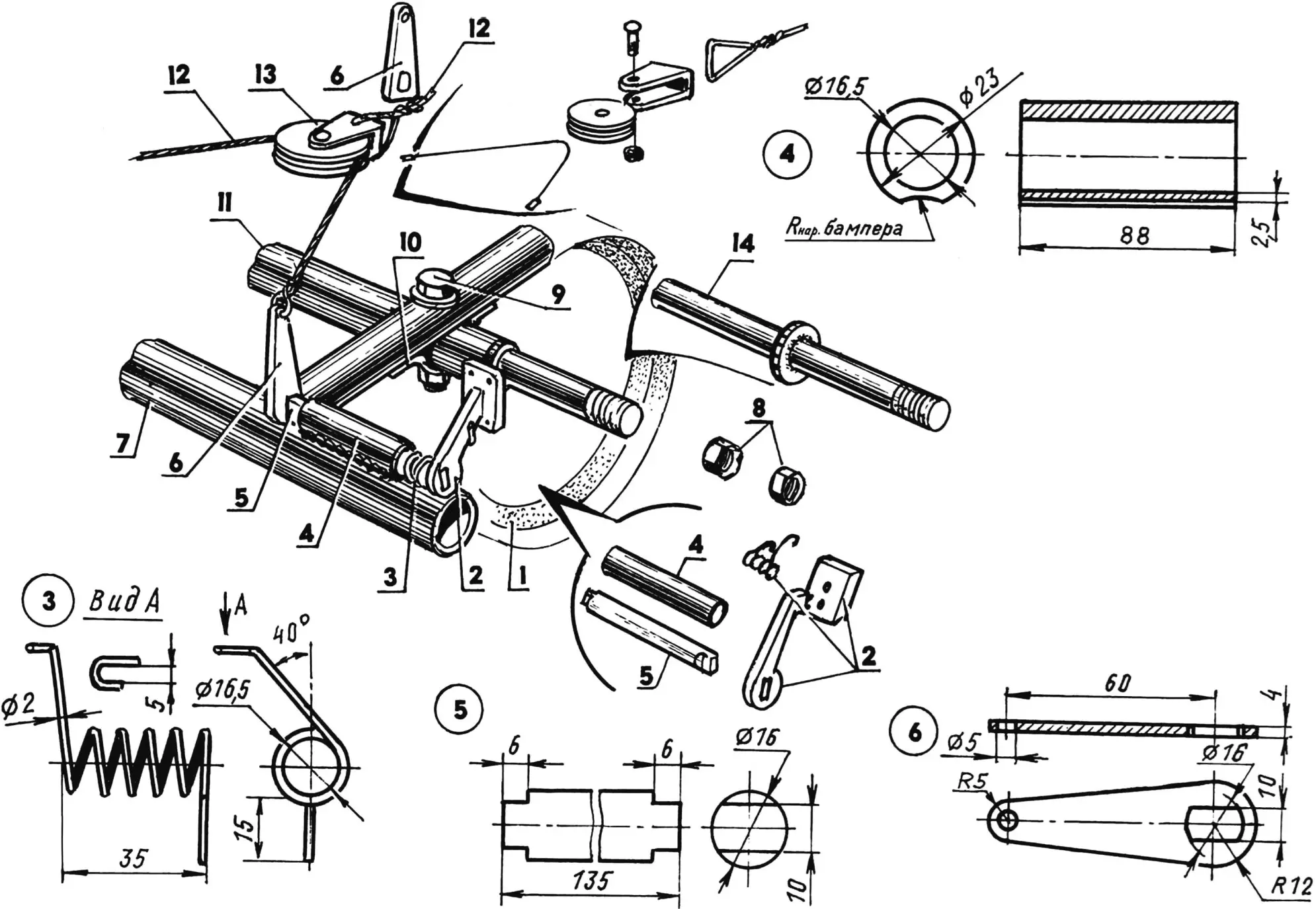
1 — wheel (from children’s bicycle); 2 — brake pad; 3 — return spring left, right — mirror image (wire Ø2); 4 — bushing (plumbing tube 1/2″); 5 — brake shaft (St 45, round 16); 6 — brake lever (St3, sheet s5); 7 — bumper (tube from bicycle frame); 8 — M8 nuts; 9 — M6 bolt; 10 — bracket (St3, sheet s2); 11 — rear axle beam with axles (plumbing tube 1/2″); 12 — brake mechanism cable; 13 — brake drive block; 14 — wheel axle
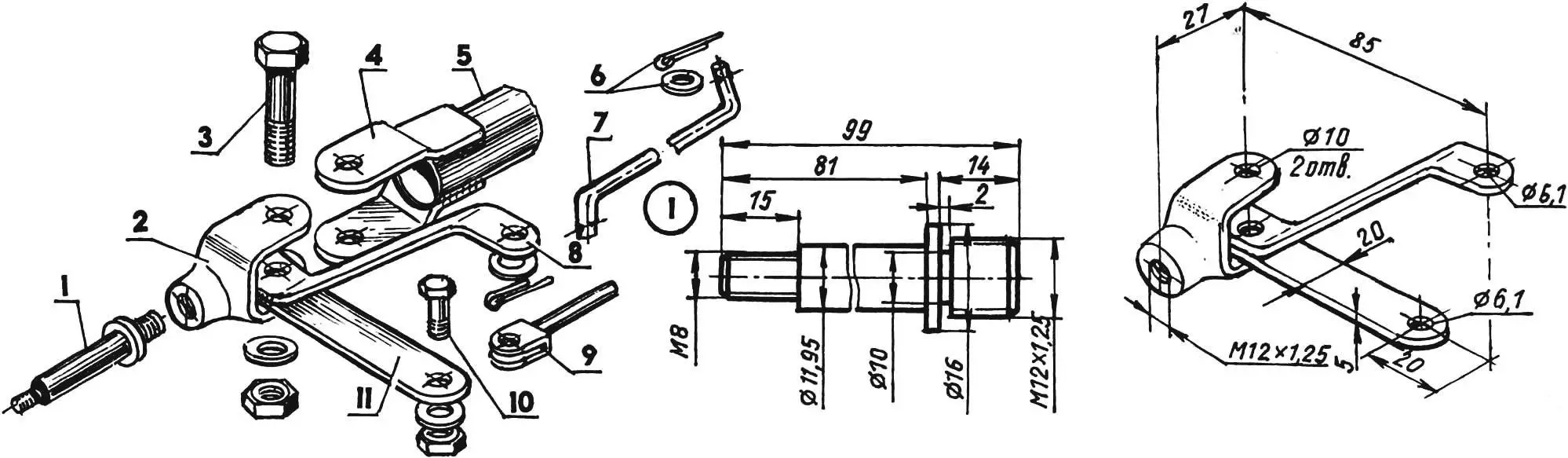
The steering is made like an automobile type. The steering wheel with a diameter of 300 mm is bent from a 10-mm steel rod and “covered” with a rubber hose. The steering shaft is a section of half-inch tube with a thrust collar welded in the middle part. The shaft is installed at an angle of about 45° to the frame plane and secured to it in two brackets through nylon bushings. At the bottom, an adapter is pressed and welded into its tube — the steering pitman arm is attached to it. The latter is connected by a rod to the pitman arm of the right wheel steering knuckle, and the lever of this knuckle is connected by an inter-knuckle rod to the lever of the left wheel steering knuckle. The steering pitman arm is short, and therefore can be installed (directed) both in the up and down positions.

1 — pad (St3, sheet s4); 2 — M3 screw (4 pcs.); 3 — lining (rubber, s8); 4 — lever (St3, sheet s5); 5 — washer
The steering knuckles are made from tie rod end forks from trucks. The ends of the forks are cut off together with the holes for the pins, and others are drilled closer to the neck. Levers are welded to each knuckle, and a steering pitman arm is also welded to the right one. These parts are made from a steel strip with a cross-section of 20×5 mm.
The wheel axles are turned with the same thread on one end as the thread in the end hole of the steering knuckle, where it is then screwed in and secured with a center punch.
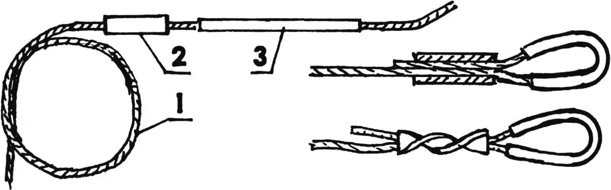
1 — cable; 2 — bushing (copper tube); 3 — thimble (copper tube)
As front wheels on the bicycle kart, front wheels from children’s three-wheeled bicycles are used. The pedal cranks are removed from them, and a machined steel hub is attached to the disc with eight M4 bolts. Two nylon bushings (plain bearings) with an internal hole of the same diameter as the wheel axle (12 mm) are inserted into it from different sides.
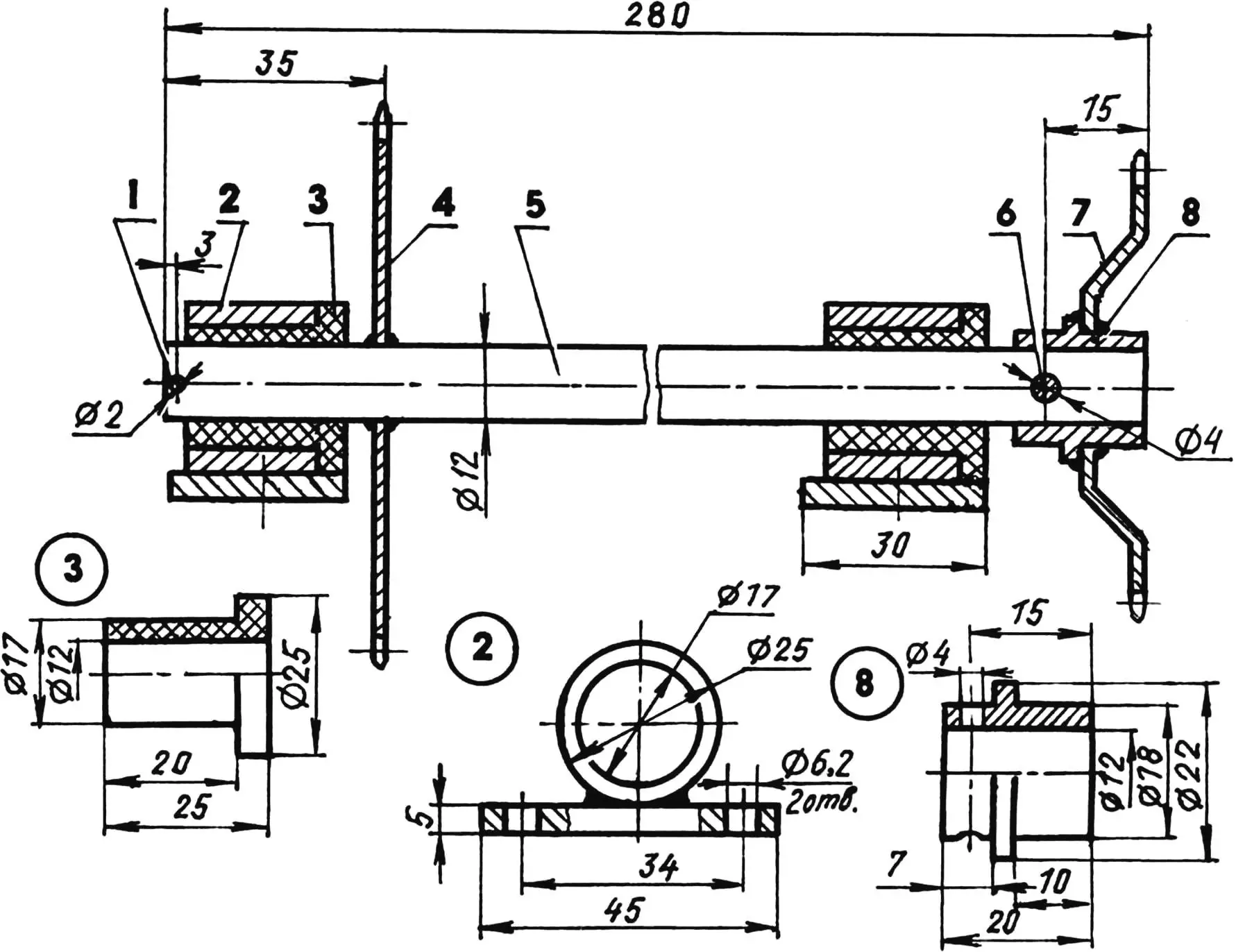
1 — cotter pin Ø2; 2 — support (steel tube 25×4, St3, sheet s5, 2 pcs); 3 — plain bearing bushing (nylon or Teflon, 2 pcs); 4 — large sprocket z = 20 (from children’s bicycle); 5 — shaft (from children’s bicycle); 6 — pin Ø4; 7 — small sprocket z = 16 (from children’s bicycle); 8 — hub (St3, round 22)
The rear axle beam, like the front one, is made from a half-inch plumbing tube. Wheel axles are pressed and welded into both ends. The rear wheels are taken ready-made, all from the same children’s bicycle “Kosmos”. They are slightly larger in diameter than the front ones, but this is compensated by the suspension level of the beams.
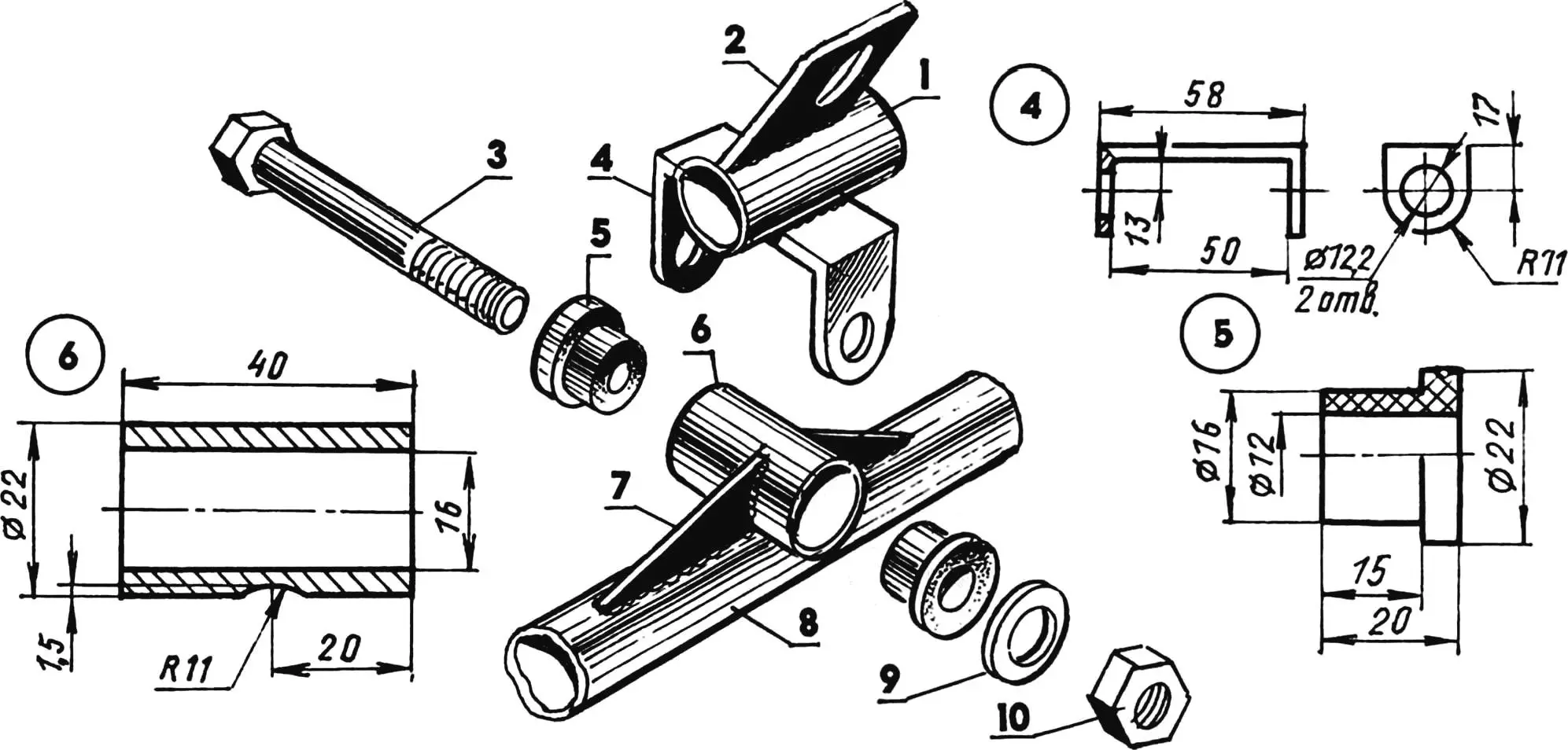
1 — front frame cross member; 2 — lower steering shaft support bracket (St3, sheet s3); 3 — joint bolt-axle M12; 4 — joint eye (steel channel); 5 — plain bearing bushing (Teflon, 2 pcs); 6 — joint suspension bushing (steel tube 22×3); 7 — gusset (St3, sheet s3, 2 pcs); 8 — front axle beam; 9 — washer; 10 — M12 nut
The beam is inserted into brackets made of strip steel, welded to the side members, and additionally secured to the frame with M6 bolts through holes drilled simultaneously in all parts of this unit: side member, beam, bracket.
1 — steering wheel axle; 2 — knuckle (truck tie rod end, modified); 3 — steering knuckle axle (M10 bolt with washer and nut); 4 — steering knuckle mounting eye to front beam (St3, sheet s3, 2 pcs); 5 — front beam; 6 — cotter pin with washer (2 pcs); 7 — inter-pitman rod (steel rod Ø5); 8 — knuckle pitman arm (St3, strip 20×5); 9 — inter-knuckle rod with end; 10 — lever axle (M6 bolt with washer and nut); 11 — lever (St3, strip 20×5)
The brake mechanism in design almost completely repeats the one that was published in No. 3 for 1978 of the “Modelist-Konstruktor” magazine. Only in my version, the brake is actuated not from a pedal, but from a handle located on the right side of the seat.
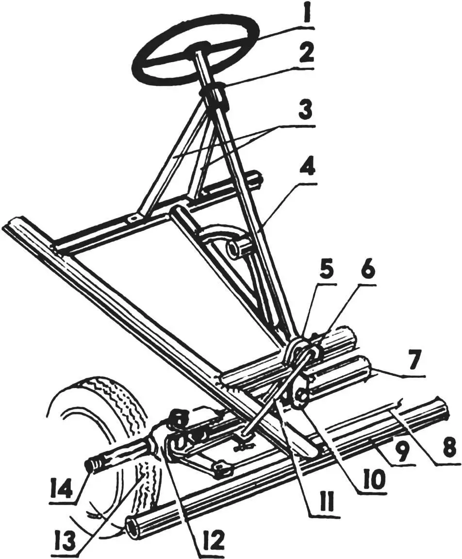
1 — steering wheel (steel, round 10); 2 — bushing (nylon); 3 — upper steering shaft support bracket (steel strip 20×3); 4 — steering shaft (steel tube 1/2″); 5 — lower steering shaft support bracket (St3, sheet s3); 6 — steering pitman arm; 7 — front axle beam (plumbing tube 1/2″); 8 — inter-knuckle rod; 9 — frame; 10 — front beam suspension joint; 11 — pitman arm rod; 12 — steering knuckle; 13 — front steering right wheel (from children’s bicycle); 14 — front right steering wheel axle
Since this issue of the magazine is unlikely to have survived even in library archives, it makes sense to include drawings of the brake mechanism in this publication as well.
And finally. The seat is made on the basis of a tubular frame from the driver’s seat of a “Kolkhida” truck. Perhaps such a frame is a bit heavy, but it is strong. A passenger handrail is welded to the top of the backrest part of the frame. The backrest and seat are formed by plywood sheets, covered with foam and upholstered with leatherette. The seat frame is attached to the bicycle kart frame by means of brackets at four points.
A. KLIMENKO
Recommend to read
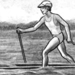 Skiing on water
The idea of water ski floats is not new, and yet such a projectile cannot be called ordinary. On the contrary, the sight of a person literally running on the waves invariably causes...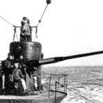 NOT ALWAYS AVERAGE “AVERAGE”
As we have noted, it is no wonder the leadership of the Soviet naval forces still in the early stages of their development in the 1920-ies turned his gaze exactly on submarines. Because...
