The term velomobile, which summarizes all wheeled vehicles with muscular traction, has been used in our country since the mid-1970s. M-K spoke about the Vita velomobile of Kharkov resident Yu. Stebchenko, as the first sign of an emerging type of vehicles, back in issue No. 7 for 1976. In the rest of the world, only practical structures intended for cargo and passenger transportation and equipped with a body-body are called this way.
At the same time, for all two-, three-, and four-wheeled bicycles with the pilot seated “car-style” (not riding on a saddle, but on a seat with a backrest), the general term “horizontal”, or recumbent, has taken root abroad. ) means recumbent bicycle. Two-wheeled bicycles of this design are often called ligrads, which literally translated from German means “lying on a wheel.”
Ligrader schemes also differ: a) in layout: short wheelbase – if the carriage is located in front of the steering column, medium wheelbase – the carriage is located near the steering column and long wheelbase – the carriage is located between the steering column and the back of the pilot’s seat;
b) according to the pilot’s position: high – the base of the seat is approximately at the level of the wheel or above (high racers), medium – approximately at or above the level of the wheel axis (middle racers) and low – below the level of the wheel axis (low racers).
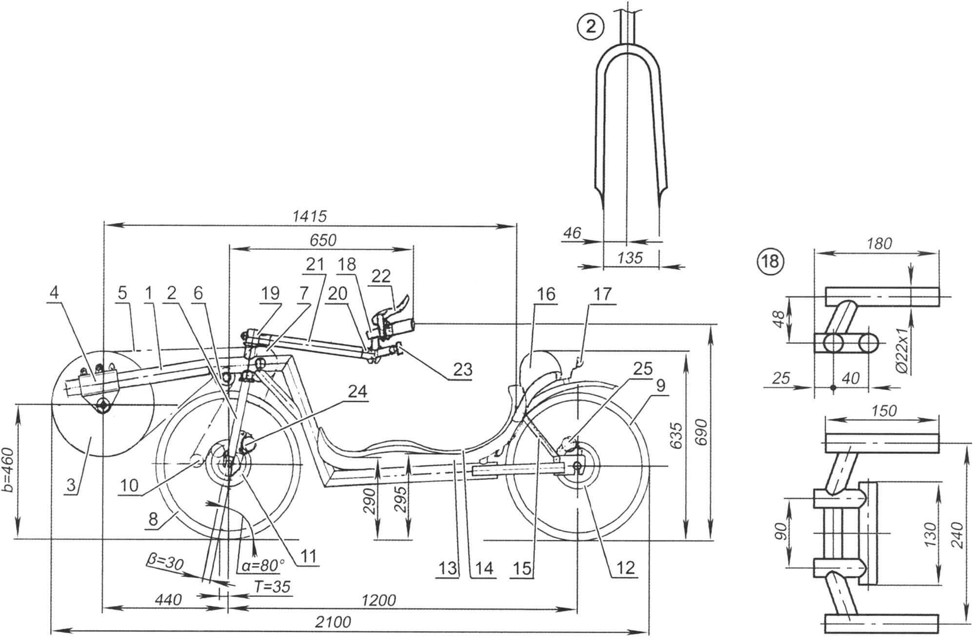
1 – frame; 2 — front fork (from a mountain bike, modified); 3 — sprocket with connecting rods; 4 — carriage fastening unit; 5 – chain; 6 — tension roller with chain guide; 7 — support roller; 8 — drive wheel; 9 — support wheel; 10 — gear switch; 11 — front brake disc; 12 — rear brake disc; 13 — sun lounger; 14 – substrate; 15 — bed brace; 16 — headrest; 17 — reflector; 18 — steering wheel; 19 — front stem; 20 — rear stem; 21 — steering lever; 22 — brake handle (2 pcs.); 23 — cycling computer; 24 — front brake machine; 25 – rear brake machine
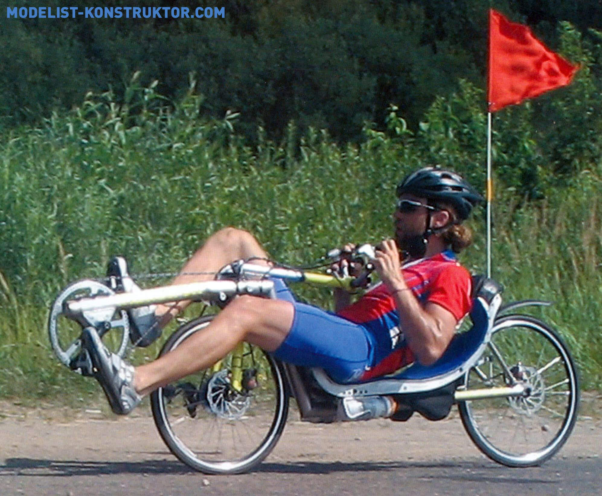
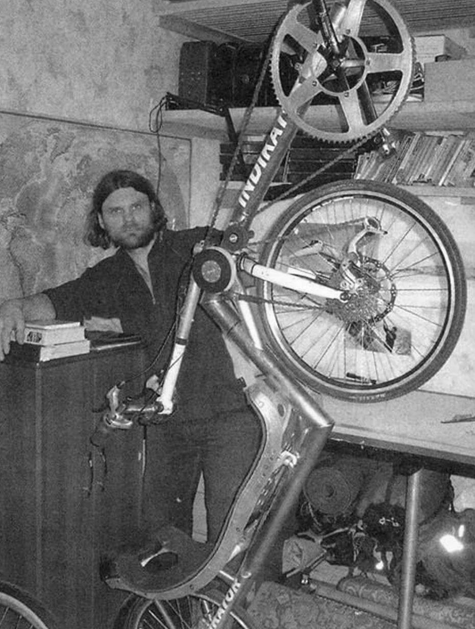
The young athlete Evgeny Nestyurin from the city of Zelenograd, Moscow Region, is a master of sports in mountain biking. For almost ten years he has been designing and creating high-speed ligraders in his home workshop, which could well become the basis (chassis) for a streamliner, but this category of high-speed pedal machines will be discussed below.
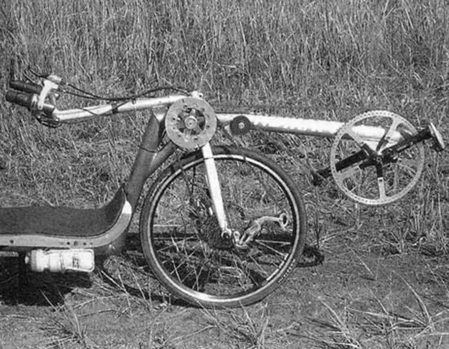
On one of his leaguers called “Indicator-2” – a short wheelbase front-wheel drive low racer with a fixed carriage (rigidly mounted on the frame) – Evgeniy became the winner of high-speed racing competitions. On it he took part in the traditional test tour of velomobiles “Golden Ring of Russia-2009” of the Moscow Club of Biotransport Enthusiasts. Nestyurin drove along ordinary highways and country roads from the capital to the Vologda outback – the ancient city of Totma – about 800 km, winning the main prize for the best design.
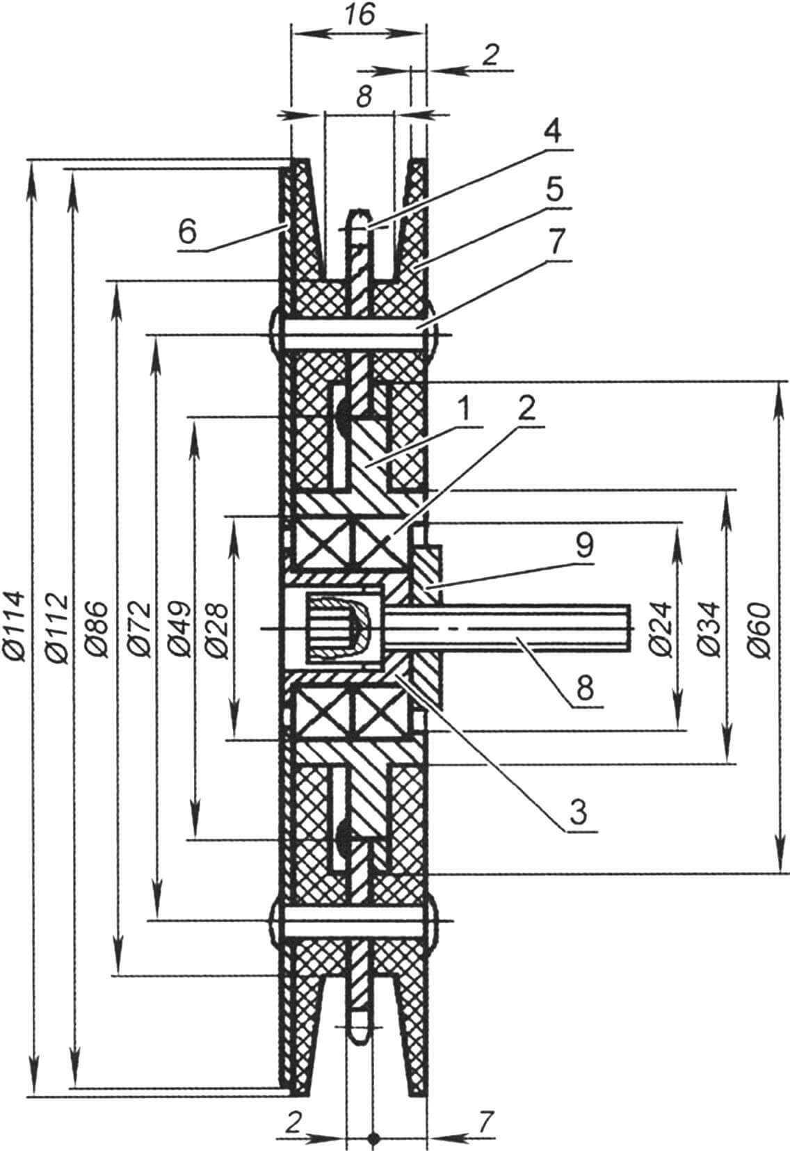
1 – bearing housing; 2 — bearing No. 0902 (15x28x7.2 pcs.); 3 – cup; 4 — asterisk (z=26); 5 — roller cheek (caprolon, 2 pcs.); 6 — overlay; 7 — rivets Ø4, 6 pcs.); 8 — axle (bolt M8x40); 9 — spacer washer Ø20×4
For the manufacture of a lightweight high-speed ligerade, the correct choice of materials is very important. Evgeniy made the first version of the “Indicator” from aluminum alloys, but some of the seams could not withstand vibration loads – cracks appeared in some places. In Indicator-2, he used titanium pipes to make the frame, and aluminum alloys for some parts. Do-it-yourselfers who do not have experience in welding such materials can easily replace them. For example, titanium – high-quality thin-walled (1 – 1.2 mm) pipes made of steel grade 30KhGSA, and smaller diameters than indicated on the drawings. The weight of the structure will increase by 2 – 3 kg, which is not critical for novice designers.
In Indicator-2, the front wheel is steered and driven. This combination is based on the ability of modern bicycle chains to twist at a significant angle without loss of performance.
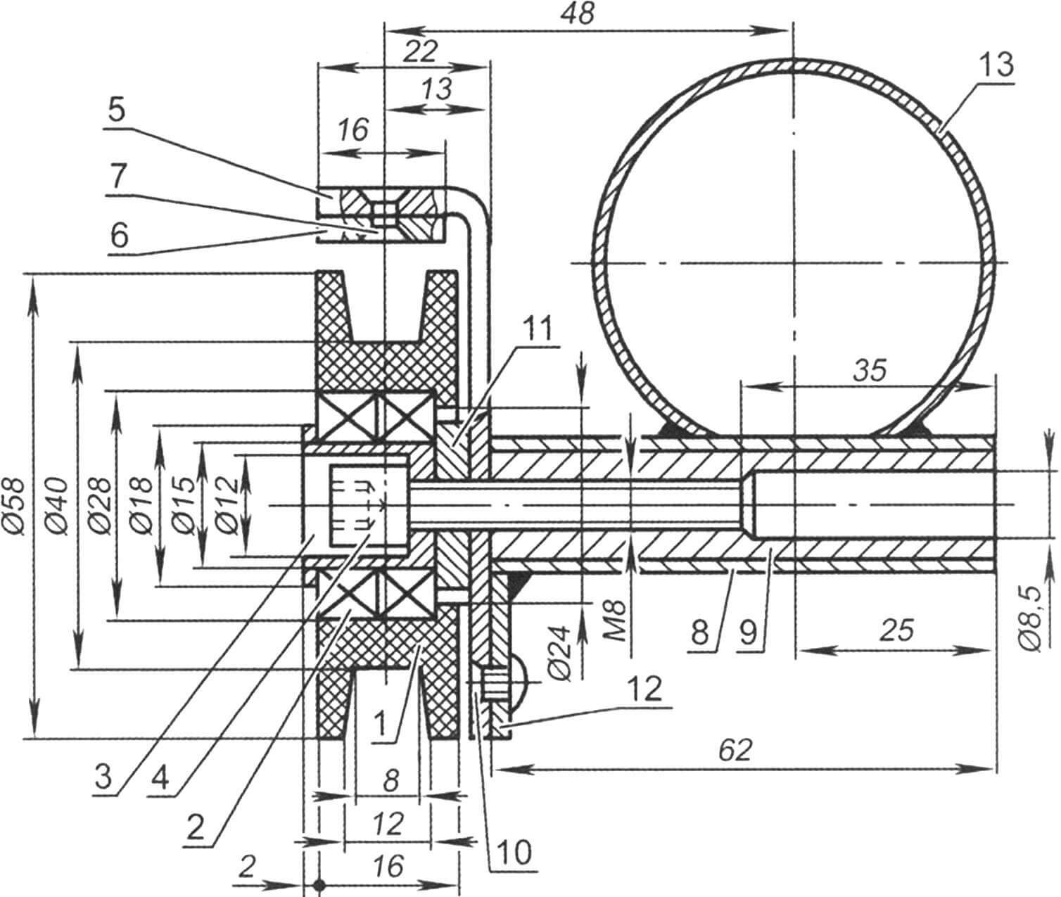
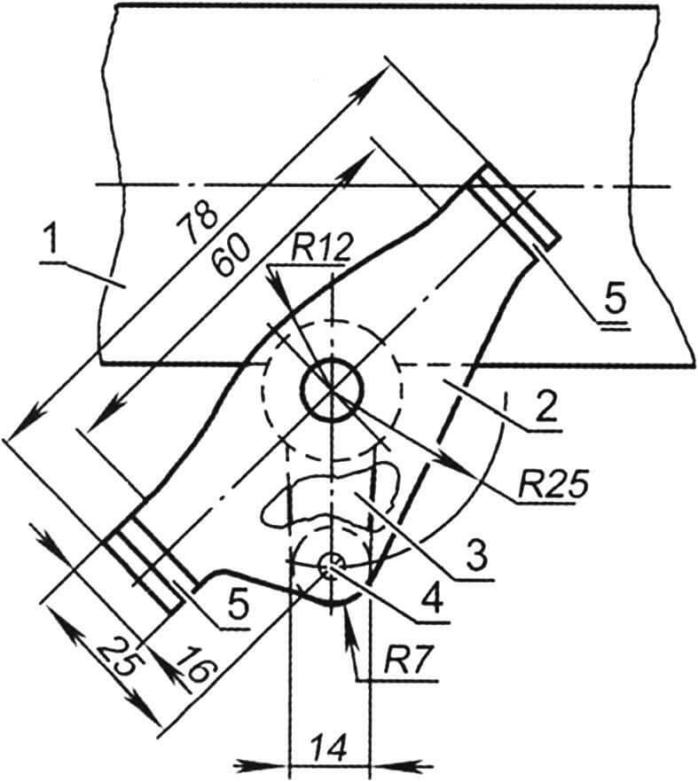
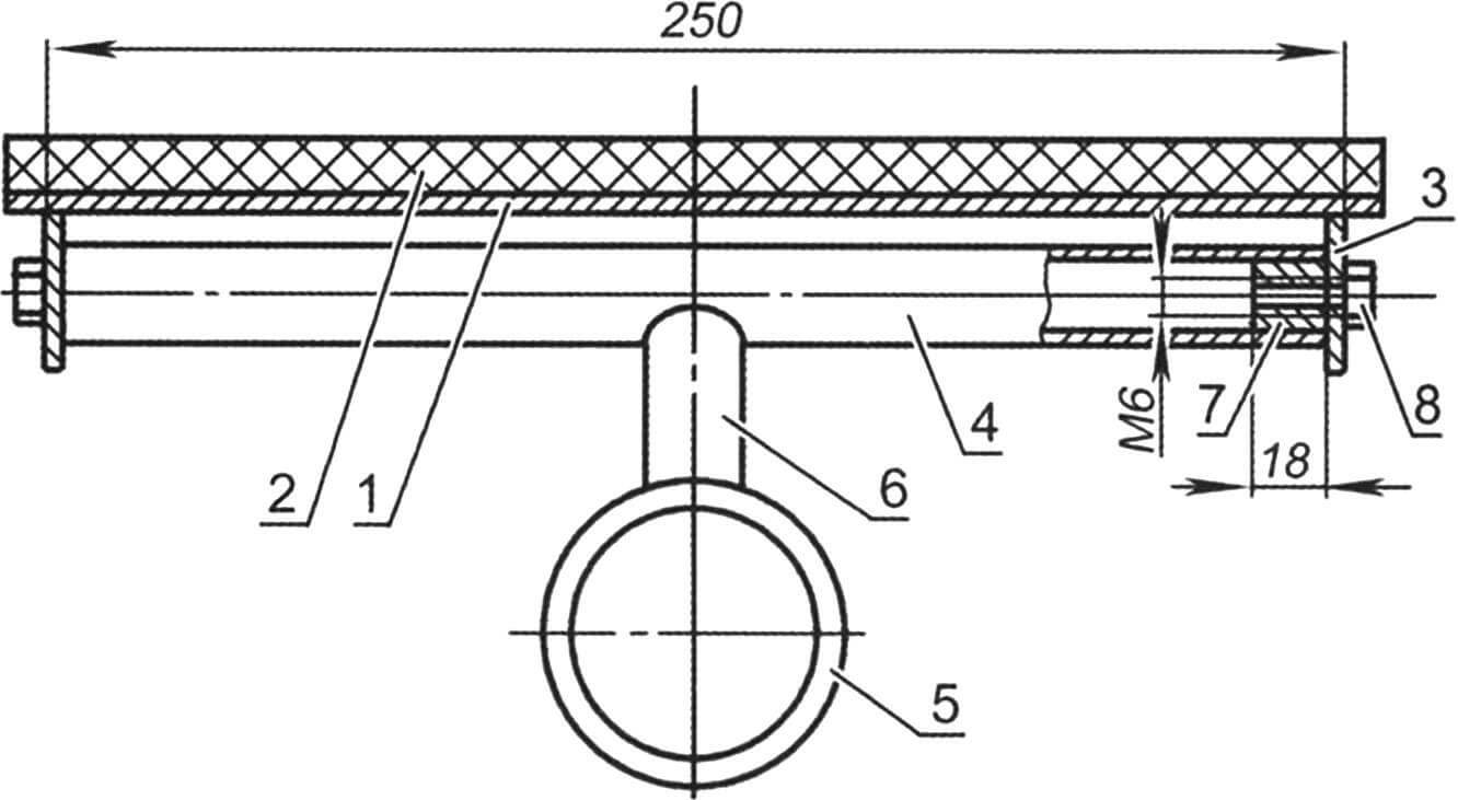
1 – tension roller; 2 — bearing No. 0902; 3 – cup; 4 — bolt M8x40; 5 — chain damper; 6 — overlay, 7 — rivet Ø3 (2 pcs.); 8 — roller holder (pipe Ø18×1); 9 — bushing; 10 — rivet Ø4; 11 — spacer washer Ø20×4; 12 — chain damper clamp; 13 – frame
To ensure dynamic stability and good controllability, it is important to correctly select the ratio of three parameters: α – the angle of inclination of the steering column, β – the reach of the front fork, T – the distance between the imaginary points of contact of the radius of the front wheel with the road surface and the intersection of the axis of rotation of the front fork with it – the so-called trail. These parameters depend on many factors (wheelbase, wheel diameters, position of the center of gravity, speed range of the liger, etc.) and are selected mainly experimentally. In Indicator-2 they are equal, respectively: 80°, 30 mm and 35 mm.
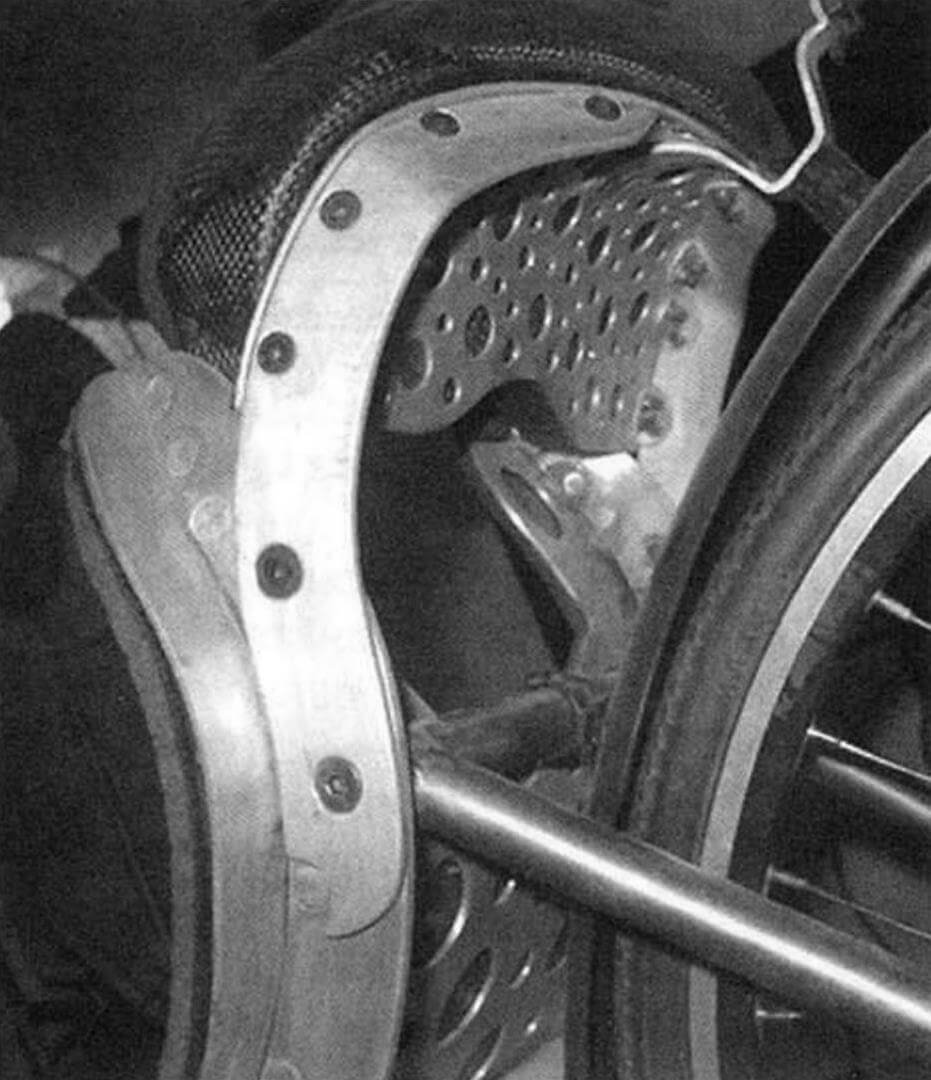
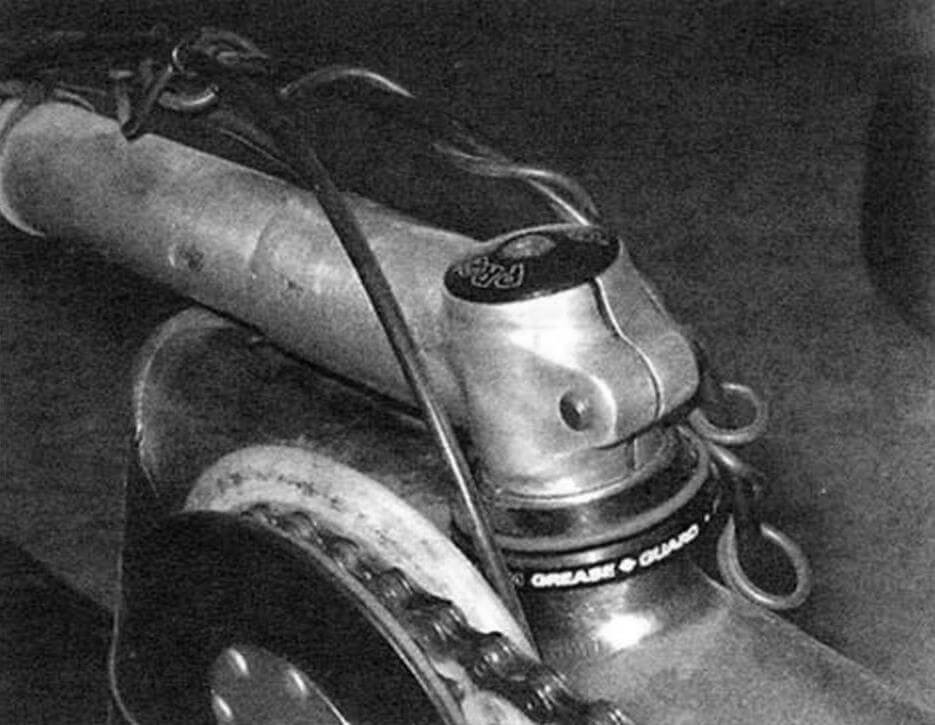
In front-wheel drive ligrades, the front fork is subject to significant loads and must be quite rigid. The Indicator uses a steel fork from a mountain bike with an overcooked stem. To accommodate the rear wheel of a regular bicycle (a nine-speed hub with a sprocket cassette), the right fork leg is slightly bent. Both rollers (support and tension) are secured to the frame using axle bolts with an internal hexagon. To do this, a bushing with a threaded hole is pressed into the holder of each roller.
The support roller is of complex design. It consists of a turned steel body into which two bearings are pressed. A standard sprocket (z = 26) is welded to the body, identical cheeks machined from caprolon are riveted to it on both sides, and on the outside there is a lining that secures the bearings in the body. A cup with a hole for the bolt-axis is pressed inside the bearings.
The tension roller is also machined from caprolon. Bearings are pressed into it, and inside them there is the same cup as on the support roller. Before installing the rollers on the frame, spacer washers are placed on the bolts to prevent the rollers from touching the frame elements.
This material of the roller and cheeks was chosen to ensure low-noise operation of the drive. For the same purpose, a chain guide is mounted on an axis common with the tension roller. Its position on the frame is determined by the clamp to which it is attached with a rivet. Linings made of sheet polypropylene are riveted to both shelves of the damper, which protect the chain from falling off the roller, to dampen noise from the chain.
1 – frame; 2 — chain damper; 3 — chain damper clamp; 4 — rivet Ø4; 5 — overlay (2 pcs.)
The basis of the Indicator-2 design is an all-welded frame. When welding it, it is very important to prevent the leash, so it is advisable to carry out this work in two stages.
The main element of the frame is a composite welded spinal tube with a diameter of 51×1.2 mm. It is best to weld it on a simple bench: a 16-mm chipboard sheet, on which the outline of the future frame is marked using bars secured with screws. The frame is marked from the construction axis “0 – 0”. While the spinal tube of the frame is on a flat slipway, a reinforcement (strut) and a gusset should be welded to it.
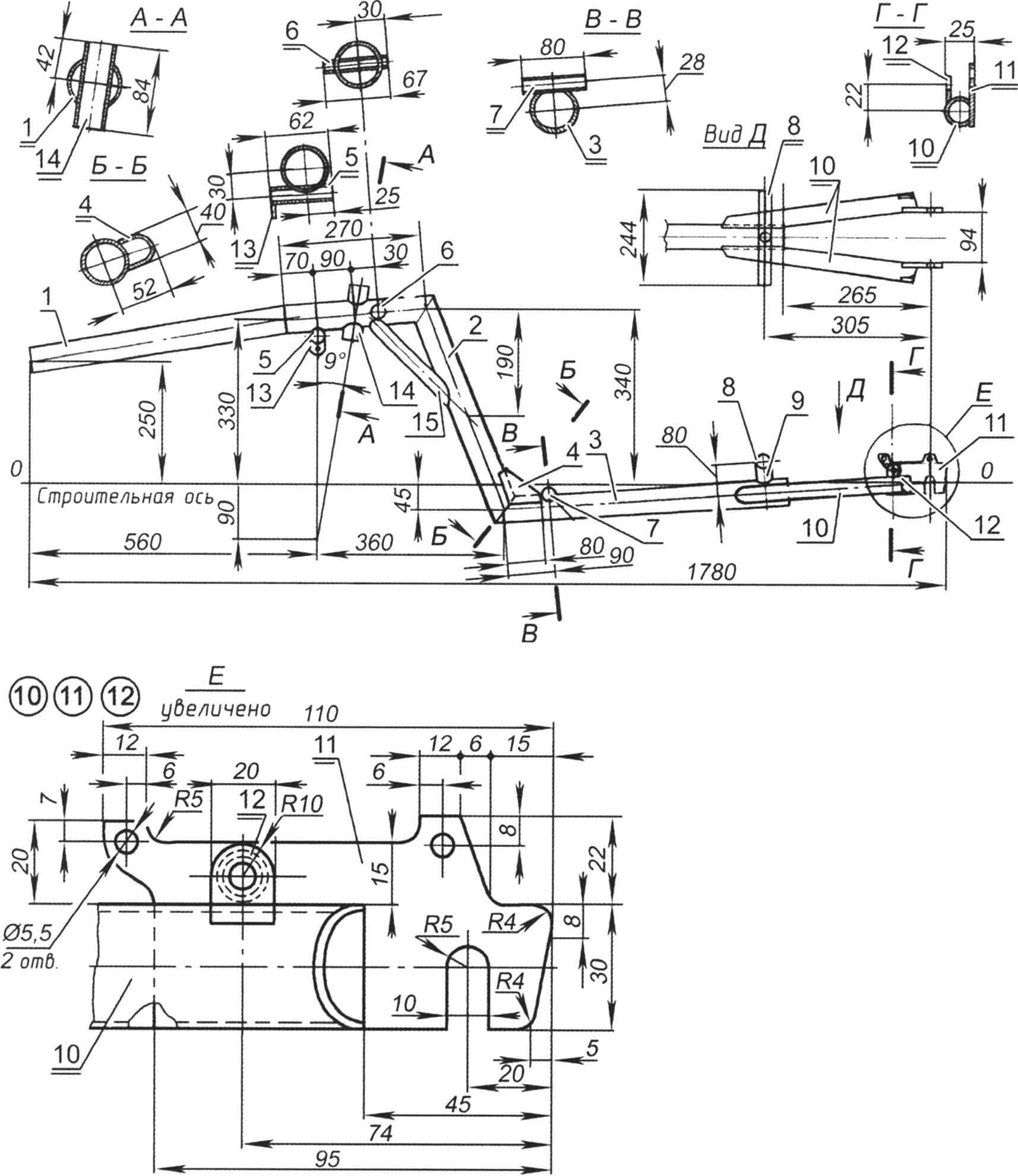
1 — extension of the frame carriage (pipe Ø51×1.2); 2 — inclined stand (pipe Ø51×1.2); 3 — ridge of the lounger (pipe Ø51×1.2); 4 – scarf; 5 — tension roller holder (pipe Ø18.1); 6 — support roller holder (pipe Ø18.1); 7 — front support of the lounger (pipe Ø20×1); 8 — rear support of the lounger (pipe Ø20×1); 9 — rear support extension (pipe Ø20×1); 10 — rear fork leg (pipe Ø30×1, 2 pcs.); 11 — dropout tip of the rear fork leg (strip s4, 2 pcs.); 12 — strut eye (strip s3, 2 pcs.); 13 — chain damper clamp (band s3); 14 — steering column glass (pipe Ø36×2); 15 — strut (pipe Ø30×1)
To perform further welding work, it is necessary to prepare a second device (for example, from a piece of channel or rectangular pipe), on which the wheel axle simulators are mounted. After this, the spinal tube assembly with the front fork and steering column cup is fixed on the slipway along with the rear fork stays and dropouts, then all the elements are tack welded. During final welding, the frame geometry should be constantly monitored. Then the remaining elements are welded. To complete the frame manufacturing operation, the open ends of the spinal tube and rear fork stays are welded with sheet metal plugs.
A pad is welded on top of the left dropout for attaching the brake machine adapter. Welding the spacer bushings between the strut mounting ears requires care and is done in dots.
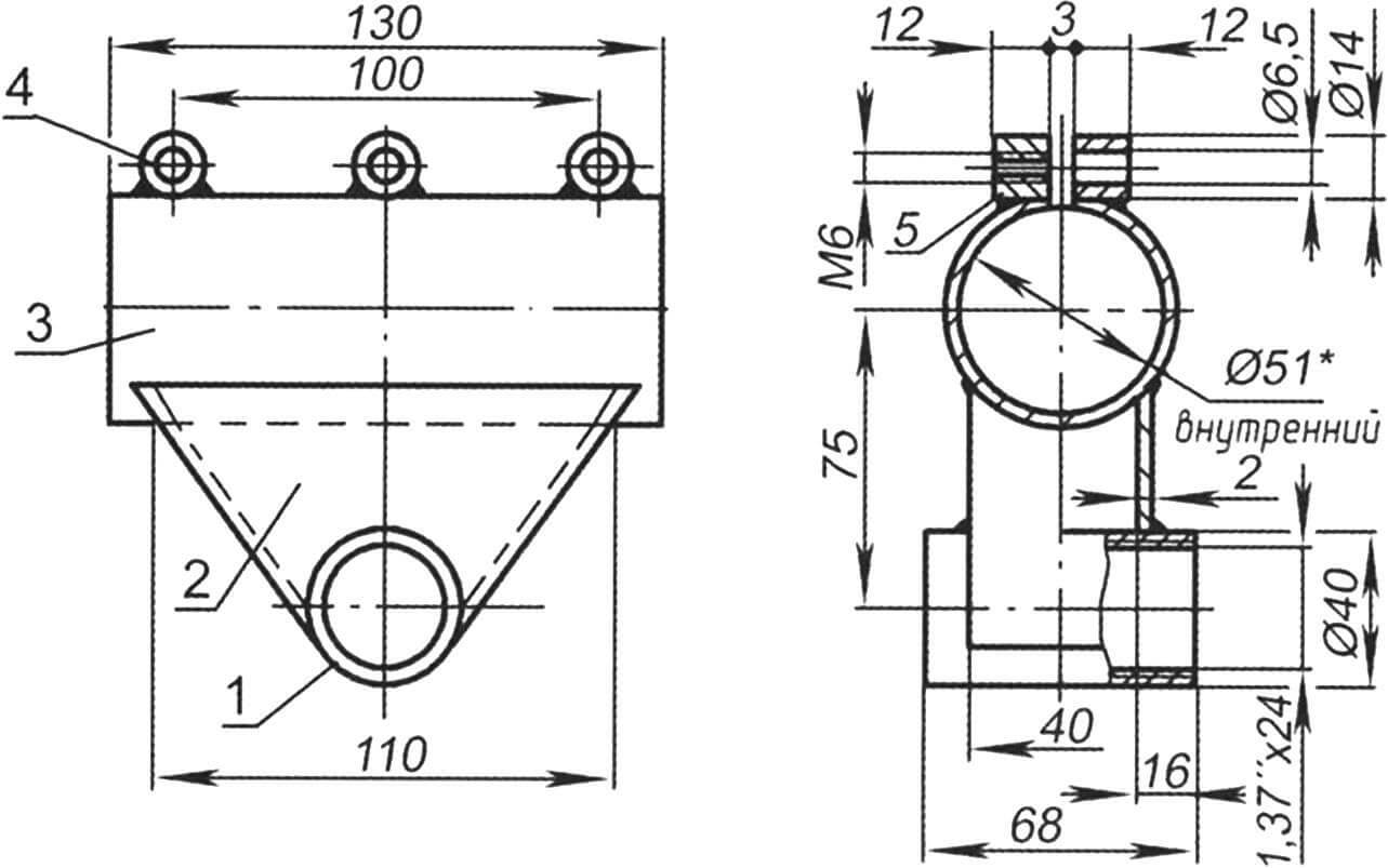
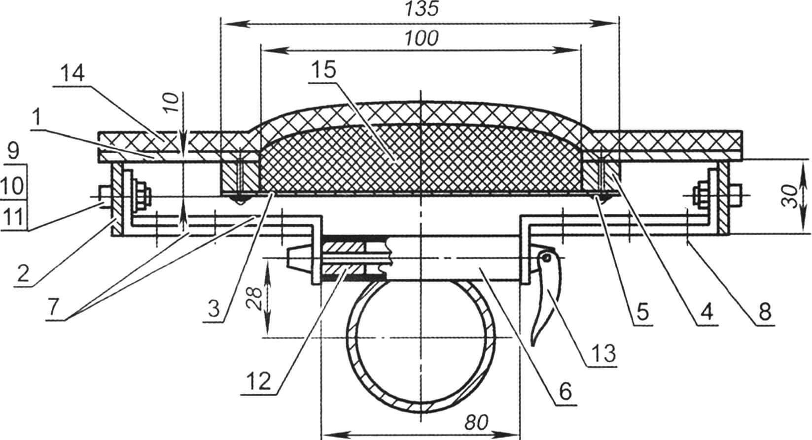
1 — carriage glass; 2 — carriage glass support; 3 — terminal clamp (pipe Ø55×2); 4 — bushing (3 pcs.); 4 — nut (3 pcs.)
The material of the carriage assembly parts is AMG-6 aluminum alloy. The carriage shell and terminal clamp bushings are turned parts. When making a unit from steel, instead of bushings, you can use standard extended nuts (“M-K” No. 11, 2011).
The support of the glass is box-type; consists of identical pairs of cheeks and linings, welded together and with a clamp pipe.
The Ligerad is designed and built for a pilot with a height of 175 – 185 cm. By moving the carriage assembly along the nose cantilever tube of the frame (stem), finer adjustments can be made to the height of the rider.
The ligerade’s seat, a particularly important design element, is custom-made for a specific pilot. Often, during the break-in period, the sun lounger undergoes serious modifications, since it is rarely possible to immediately make it comfortable.
The cyclist, or rather his spine, with an almost horizontal landing, experiences unfavorable alternating loads in the back-chest direction when moving over uneven roads. Therefore, the profile of the lounger must exactly match the contours of the pilot’s back. There are many original methods of taking measurements. The designer proceeded as follows: he mocked up the main elements of the ligerad on a flat floor and placed an ordinary pillow under his back. The imprint left on it lasts for several minutes, which is enough to take measurements.
The bases of the lounger and headrest are made of 2 mm thick duralumin sheet and perforated for lightness. The sidewalls are also made of the same material, but 3 mm thick. The sidewalls are connected to the bases using rivets and corners in the form of round washers bent along the diameter. Moreover, the author cleverly and practically used old coins as washers.
1 — base of the lounger; 2 — side of the lounger; 3 – bottom of the niche; 4 — spacer; 5 — rivet; 6 — front support of the lounger; 7 – corners; 8 — rivet; 9 — bolt M5x20; 10 — M5 nut (self-locking); 11 — washer; 12 — bushing; 13 – eccentric clamp; 14 — bed base; 15 — lounger pillow
The shape of the front and rear parts of the lounger also depends only on the physique of the pilot. For example, in the front part, its rounded edges in the buttock area are sometimes bent down at an angle of approximately 15° – 30° in order to eliminate abrasions and at the same time maintain contact between the pilot and the sunbed during power pedaling. In Indicator-2 this turned out to be unnecessary. The rear part of the base of the lounger is bent forward to form shoulders that keep the pilot from moving backwards; it also has a shaped cutout to relieve the load on the cervical spine.
A 100×290 mm hole was cut out at the base of the lounger opposite the pilot’s sacrum and a niche was formed. To do this, on the underside of the lounger, the bottom is attached to it using rivets and a rigid gasket. The base of the lounger is covered with a 10 mm thick tourist foam mat glued to it, while an additional pillow of variable height is pre-laid in the niche.
The headrest, a separate element of the lounger, is attached to it with four countersunk screws and nuts. Glued to the base of the headrest is a shaped pillow made of several layers of the same “foam”, covered with a soft fabric cover.
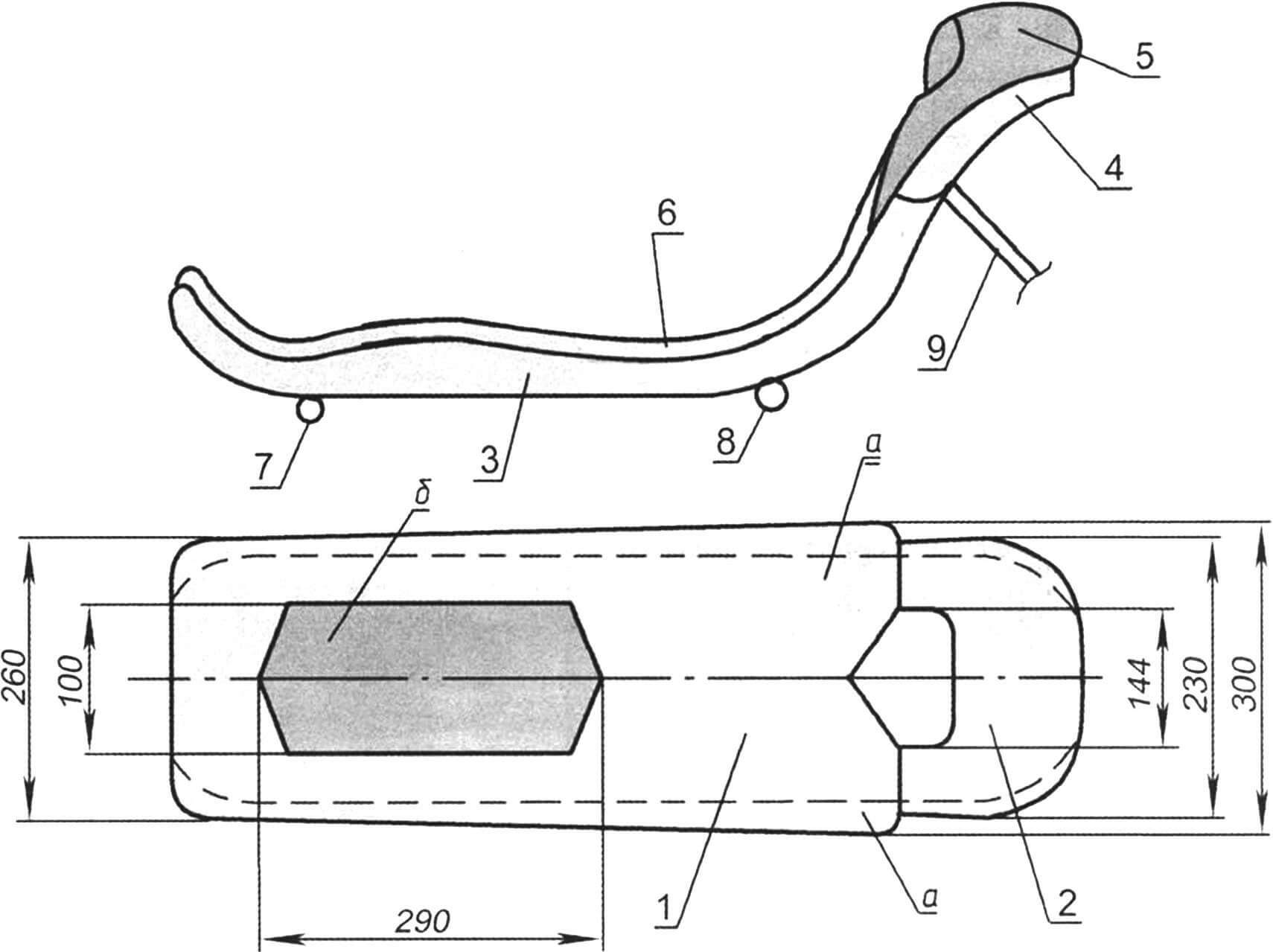
1 – base; 2 — base of the headrest; 3 — side of the lounger (2 pcs.); 4 — headrest side (2 pcs.); 5 — headrest pillow; 6 – mattress; 7 — front support; 8 – middle support; 9 — rear support (strut, 2 pcs.); a – shoulders; b – niche of the lounger pillow
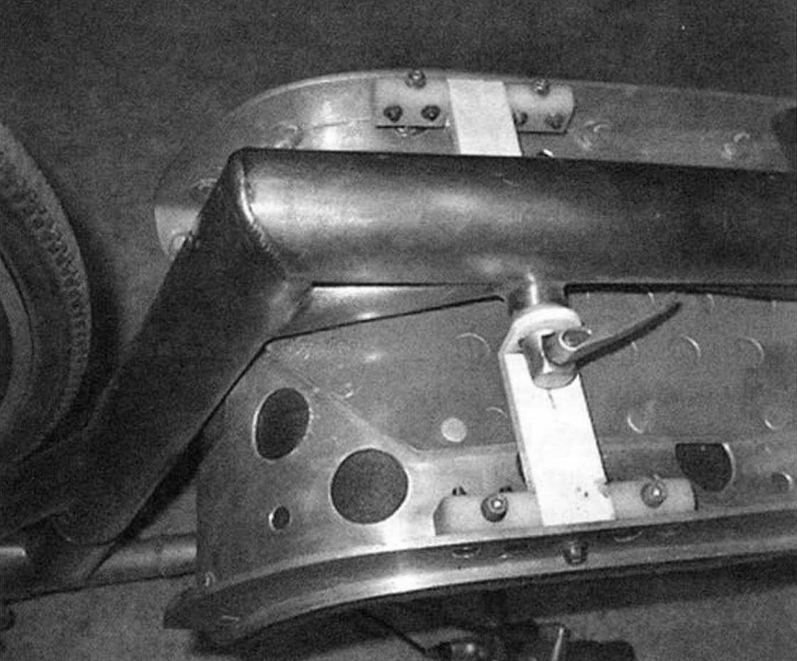
The lounger is removable, attached to the frame at three points: to the front support on the horizontal part of the spinal tube – using two brackets made of pairs of corners riveted together and an eccentric clamp of the bicycle saddle; to the middle support – using two countersunk M5x20 screws and threaded bushings pressed into the ends of the support; to the rear fork feathers – using struts.
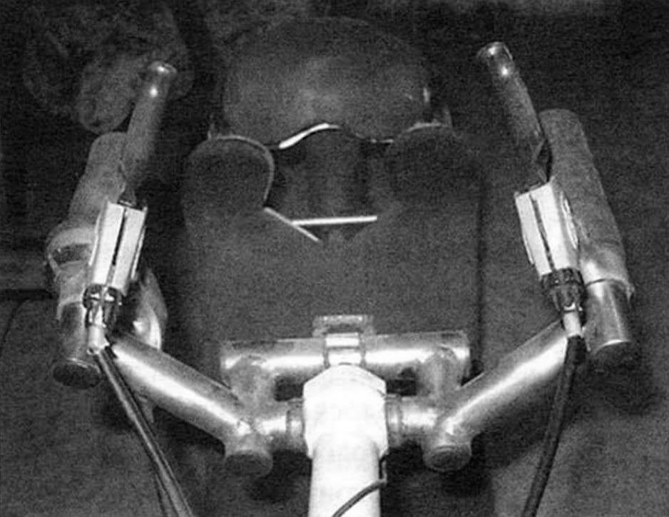
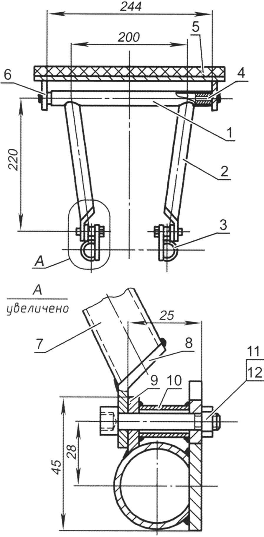
The steering wheel of the ligrad is welded from pipe sections with a diameter of 22×1 mm. For the manufacture of the steering stem, two standard ones were used: with a terminal clamp installed on the front fork stem, and a split one – with a pad for attaching the steering wheel itself using two bolts. Both of these stems are combined: welded to an extension made of a pipe with a diameter of 25 mm. Decorative rubber plugs are inserted into the open ends of the steering tubes.
The rest of the low racer is equipped with standard bicycle parts and components.
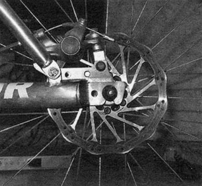
A cartridge is installed in the carriage assembly: a capsule that combines the carriage shaft and standard ball bearings. The length of the connecting rods is 170 mm. The drive sprocket has 82 teeth. Wheels with a diameter of 22 inches (510 mm) are equipped with narrow (19 mm) rubber tires designed for high pressure, up to 8 atm. The drive wheel has 36 spokes, and the support wheel has 32. The diameter of the disc wheel rotors is 160 mm. Both brake machines are mounted on the fork stay brackets using adapters that provide brake adjustment. On the handlebars there are handles for the front and rear disc brakes, a 9-position gear shifter and a cycling computer. Only the rear wheel is equipped with a mud shield – the pilot is protected from splashes from the front wheel by the wide spinal tube of the frame and the sunbed. Retroreflectors are also installed: at the rear – red on the mud flap mounting bracket: at the front – white at the spinal tube plug. There is also a convenient place for a headlight – if necessary, it can be easily mounted using plastic electrical clamps.
1 — rear support of the lounger (pipe 18×1); 2 — right strut (pipe 18×1); 3 — rear fork leg (tube 30×1, 2 pcs.); 4 — M5x20 screw; 5 – substrate; 6 — sidewall of the base of the lounger (sheet s3); 7 — left strut (pipe 18×1); 8 — end of the strut; 9 — eyelet for fastening the strut; 10 — spacer (pipe 15×1); 11 — bolt M6x35; 12 — self-locking nut M6
It takes E. Nestyurin almost a year to create one ligerad – the author very carefully works out every detail of the design, which is why his cars look like factory ones.
Since almost the entire “Indicator” is made of corrosion-resistant materials, no paintwork was applied, with the exception of the steering wheel stem.
The total weight of the structure is 17.3 kg.
Not everyone will master the ligread the first time and learn to ride it confidently, especially with such a low seating position. Even experienced cyclists, who have grown into the saddle of a traditional bicycle, sometimes relax, sitting on a low lounger. And for some, just a few minutes are enough to feel this amazing machine, to become one with it. And such a daredevil rushes to the envy of those around him, literally flying over the road…
This could be the end of the story about a high-speed bicycle. But do you know what a low-racer pilot, especially a young one, dreams of in his soul? He dreams of turning it into a streamliner and, of course, with the best fairing in the world. And then – fight for records! If you don’t believe me, then try making your own low racer. What if this becomes your first step to victory?
Trained athletes on modern body velomobiles (with fairings) are able to cover distances of over 1200 km with an average speed of over 50 km/h in a day’s run.
The absolute world record for a wheeled muscle vehicle is 133.3 km/h. It was installed in September 2009 in Nevada at the traditional annual high-speed races at Battle Mountain by Canadian racer S. Whitingham on the Varna streamliner velomobile designed by G. Georgiev, also a Canadian, Bulgarian by birth (hence the name of his streamliner series – “Varna”).
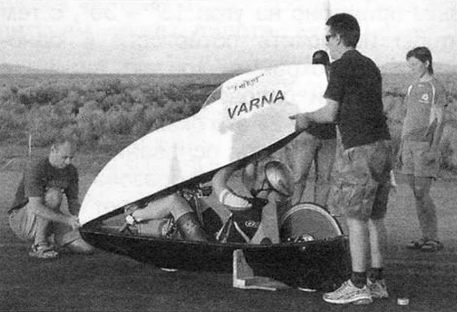
Such outstanding results were achieved mainly due to the perfect aerodynamic shape of the fairing body. When reaching a speed of about 30 km/h, almost 85-90% of the cyclist’s energy is spent on overcoming the resistance of the oncoming air flow, and at higher speeds – up to 95%. Streamliners, according to the terminology adopted by the World Muscle Vehicle Association (WHPVA), include structures equipped with fairings with high aerodynamic characteristics and intended for establishing sporting achievements. At the same time, the pilot is so tightly “packed” into the car that for the start and finish, and even to land and exit the apparatus, the athlete requires a third -party help of the team members.
The start and finish of the high -speed stop on the streamline usually occur as follows. The pilot is placed in the lower part of the fairing, which stands on the lodge. After that, he stretches his hands forward to the steering wheel, as a result of which the scope of the shoulders taps. Next, the assistants put on the upper part of the fairing and the gap between both parts are sealed with tape. The assistant, being on roller skates, covers the streamliner with his feet, frees him from the lodgent and, in this position, the “pilot -assistant” duet moves from the place. After slight acceleration, the Streamliner pilot begins independent movement. The streamliner finished passing the distance at the end of the brake area is caught by team members and free the pilot from the fairing.
The creation of high -speed bike mobiles with light aerodynamic fairings made of composite materials (mainly from carbon fiber) is a complex and high -cost engineering task.
Remembering the story, I would like to note that the Vector cycle, for the first time overcoming a bar of 100 km/h in 1980, was three -wheeled. But starting in 1986, all absolute records for the speed of cycling were set only on two -wheeled streamlines.
In most modern bicycle cars (applicants for records), the chassis is integrated into the overall design. Nevertheless, there are streamliners in which two -wheeled rimbents are used as a chassis, they can be removed from the shell and used for competitions in independent classes (according to the same international regulations) – without a fairing.
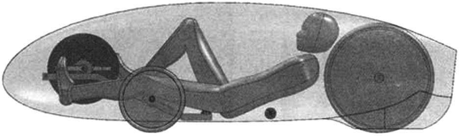
As a rule, according to the scheme, these are loureders who have a low center of gravity, on which the pilot is located almost horizontally. In streamlines of such a scheme, the pilot’s seat is called a sunbed.
1 – base of the sunbed; 2 – substrate; 3 – sidewall of the base; 4 – the average support of the sunbed; 5 – frame, 6 – support of the support; 7 – threaded sleeve; 8 – screw M5x20
To reduce the power of aerodynamic resistance, the designers in every possible way strive to reduce the Midel Streamliner – the area of the largest cross -section of the fairing. Midel is determined mainly by the anthropometric parameters of the pilot. The gap between the athlete and the capsule is measured literally by millimeters. When designing and drawing a Midel, two main parameters are important: the projection area of the omission of the pilot’s feet and the width of its shoulders (the maximum width of the fairing of the best streamliners is only 380-420 mm).
When laying the Loarser, you should use a two -dimensional model of the pilot. For this, it is convenient for an ergon, developed and successfully used for decades with Czech designers of Tatra cars: it is drawn using only straight lines and circles. Its proportions are well consistent with pilots with growth of 160 – 180 cm. The elements of the layout can be made from a solid transparent cover of a notebook or folder and fastened with rivets in hinges, for example, from small carnations.
Initially, it is necessary to determine the position (size “b”) of the carriage axis. To do this, you need to set constructive parameters: size “A” – the minimum (usually 80 – 120 mm) distance from the heel of the pilot to the road and “D” – the length of the connecting rods (usually 150 – 170 mm). Then set the size of the carriage over the base of the sunbed (usually 120 -180 mm). Then draw several options for laying the position of the pilot. They will determine the optimal contours of the Mideliner Middeliner. The finally longitudinal and transverse sections of the fairing are specified during field mocking.
Individual designers and professionals are engaged in the creation of streamlines. In the battle for speed records, the most modern materials, computer technologies and modeling are used. But, surprisingly, the most fast Varna bicycles for today are not created by an engineer, but were the fruit of the experience and talent of George Georgiev – a sculptor by education.
From the editor
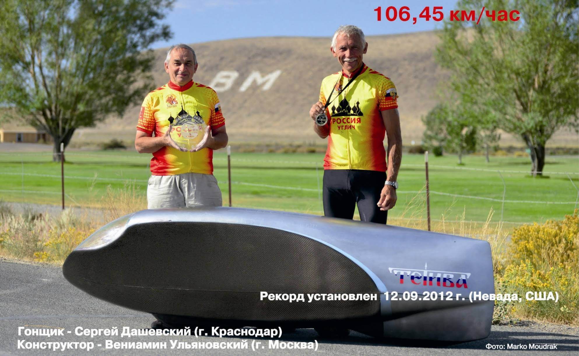
09/12/2012, a racer Sergey Dashevsky from the city of Krasnodar on the TETITN streamline, Moskvich Veniamin Ulyanovskiy, on a special trace in Nevada (USA), set a new record of Russia – it developed a speed of 106.45 km/h.
V. Ulyanovsky
Recommend to read
 CUTTER BOOKBINDER
After reading in the "M-K" No. 2, 1988 on "the guillotine" for trimming the binded books, I decided to share my experience. Moreover, they issued the fixture due to design complexity not... NOT FROM THE COLD
Truck drivers all over the world like to wrap the "wheel" wheel with a plastic cord or a plastic tube: rough, but it is believed that beautiful and practical hands do not slip. Owners...
