As the drive of the front wheel, used rear brake hub. Conversely, the rear wheels serve as the front; they are set on a makeshift axle, which is structurally similar to pedal. To use these wheels with regular axles under the console fixing is impossible due to the low strength of the regular axes of bending. It is also impossible to attach them to Bicycle handlebars welded to the frame, as the structure will not be rigid with respect to lateral loads of the roll and the wheel will no longer be parallel to each other.
Made rotatable frame of the rear fork chain bike MMVZ or “Desna” and the front forks of the same bike. Is separated from the frame chain fork bracket axis that with a hacksaw exempt from the strut tubes. Before mounting the front fork it is clamped in a vise and throw the feathers on the value of 110…115 mm, then remove them from the brackets.
In chain the plug is inserted the rear wheel, the axis of which should be in the center of the brackets and fitting the front fork, putting on her the cut ends of the feathers to the chain brackets of the plug. The correct alignment of the plug relative to the wheel must be achieved by fitting the ends of the feather of front fork, as well as to maintain a distance from the wheel axis to base of tail front fork, is approximately 275…280 mm. When alignment is ensured, and the angle between the straights forks is 90°…95°, serverlimit connection of the ends of the front forks and brackets, insert one steel pin Ø 2,5…3 mm (wire or nails) and clench them. Now the wheel can be removed and once again to check the connection. Then prepare two tubes of Ø 12…14 mm for the connection of the carriage with the base of the front fork. The pipe should have an oblique cut to be customized.
Front frame ready for welding and soldering works. First gas welding welded two pipes in its place, and then solder the brass connections zastepowane all. You should achieve careful soldering, to then file off the excess. If welding or soldering has been performed carefully, the paint coating the forks are very hurt, and picking up enamel, these places can tint. It should be mentioned that the steering tube of the front forks, the author has shortened to 140 mm for the best viewing between the front and rear frames, and also for reduction of mass.
The connection of the rear frame beam (Fig. 1) are adjustable, but rigid enough: this quality largely depends on the rigidity of the structure. Therefore, the connecting pipe must have a diameter not less than 36 mm and a wall thickness not less than 1.8 mm (the elements of the folding frame to use for this purpose should not).
Before starting to work on the elements of the rear frame, to its side view is drawn in scale of 1:1 and applied to this template is prepared for welding details. When items are customized, they are pre-connect arc welding, produce a visual alignment or measure the symmetry and produce a final gas welding rear frame, privaris median pre-sleeve halves to the frame. They provide alignment of the inserted rod Ø 14 mm. the Latter is welded a connecting pipe, and the bracket of the seat.
If assembled rear frame profile matches scale drawing, is pre-welded mounting plates. They have two holes for connecting with flaps and two coaxial holes for installation tick the manual brakes, if the conditions they need.
Tail section rear frame is raised, which is caused by the desire to eliminate a noticeable deflection of this part of the velomobile.
The seat frame (Fig. 4) are made of solid aluminum alloy sheet with thickness of 2…3 mm, having cut from it the contour of the workpiece from the surface. Then draw lateral (inner) profile of the seat frame in 1:1 scale, using the grid. Flex the blank frame on this profile and strong mallet blows make ochibka boards (the Central part up to a height of 20…25 mm, bottom and top to 10…15 mm).
Fig. 4. The calculation of the seat frame.
It should be mentioned that if the sheet is too brittle, that the edge of the workpiece must be carefully annealed without heating to a reflow edge. Work on the frame requires accuracy and careful execution, particularly of the head restraint. The sections of the framework with holes for the support struts (see figure 1) need to strengthen two planks, prilepov them to each limb. All sharp edges are trimmed and rounded. If the changes obtained form of seats not expected, then glued on its frame transverse strips of foam the length of 60…80 mm and a thickness of 30…40 mm, additional fixing them with a cord in areas of sharp bends through the drilled holes. On top of the foam adhesive qualities beautiful solid fabric. Better if it feels slippery: such a casing when planting allows comfortable posture and will not cause additional friction when riding.
The rear wheels, as stated above, have their own axle (see figure). Driveshaft — the part responsible and must be made of high quality steel and tempered HDTV with a deep vacation and thoroughly customized to the hub of the wheel.
Fig. 5. Half shaft of the rear wheel.
The trunk in the form of a lattice (in this design from the industrial refrigerator) aluminum alloy sheet thickness of 1…1.5 mm; mounted in any way from the bottom to the rear frame. A small carrier bag mounted on the seat back, is used for tool storage and pump, it also can carry small items or products. It is easy to do from the school portfolio and prilepite or screwing to the seat frame.
Those who are fit seem inconvenient, it is recommended to make a control flap on a hinge.
When tested in a velomobile, check the roll-forward follows: to disperse at horizontal section of level road to the maximum speed (35…40 km/h) and from the reference notes to measure the path of inertia. As practice shows, it needs to be 175…200 m.
Tire pressure: front wheel 3…3,5 kg/cm2 , rear 2,7…3 kg/cm2 ; these figures in the operation of the velomobile, it is desirable to monitor every two weeks. You should pay attention to the parallelism of the rear wheels by measuring the distance between their rims front and rear: the difference in the measurements should not exceed 1…3 mm.
The velomobile has a retro-reflector and lighting with battery pack. Signs, decals on the seat-back is performed by a sticker. They are cut from fluorescent foil applied in the design of traffic signs. It is also desirable to have a small box attached to the velomobile and visible from all sides. This is enough to attract the attention of other drivers to unusual crew.
To store bicycles in the apartment, as the dimensions allow it to raise the lift and to carry through a standard doorway door.
Technical characteristics of the velomobile
Type — road, for teenagers and adults
The number of places is one
Drive — pedal, chain drive on the front wheel
Number of teeth:
sprocket — 51
slave — 15
Brake — foot operated, front wheel drive
Tyre size, mm — 40 — 406 (20″X13 /4 “)
The height of the lower part of the seat above the road, mm — 40
Seat — polulezhachee, like chaise
Base, mm — 840 — 850
Track, mm — 630 — 640
Overall dimensions, mm — 1650X880X725
Weight, kg — 18 — 20
V. MAZURCHAK, engineer, master of sports of the USSR, Poltava
Recommend to read “VERTICALBAR” In the construction of the great importance of the so-called mark (vertical dimensions, the count of which produce from the finished floor level of the first floor). When you craft a... TO HELP THE GLAND Utilities are widely used shut-off valves — they are in all water inlets in the house and each apartment. Earlier these devices were made of iron or steel: casing — cast iron, and the... 
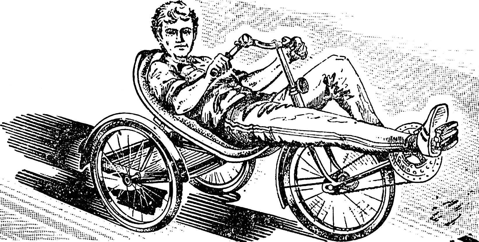 The proposed design is the winner of one of the contests of velomobiles in the Lithuanian city of šiauliai.