WE are BUILDING the PLANE (“Argo 02”)

WE are BUILDING the PLANE (
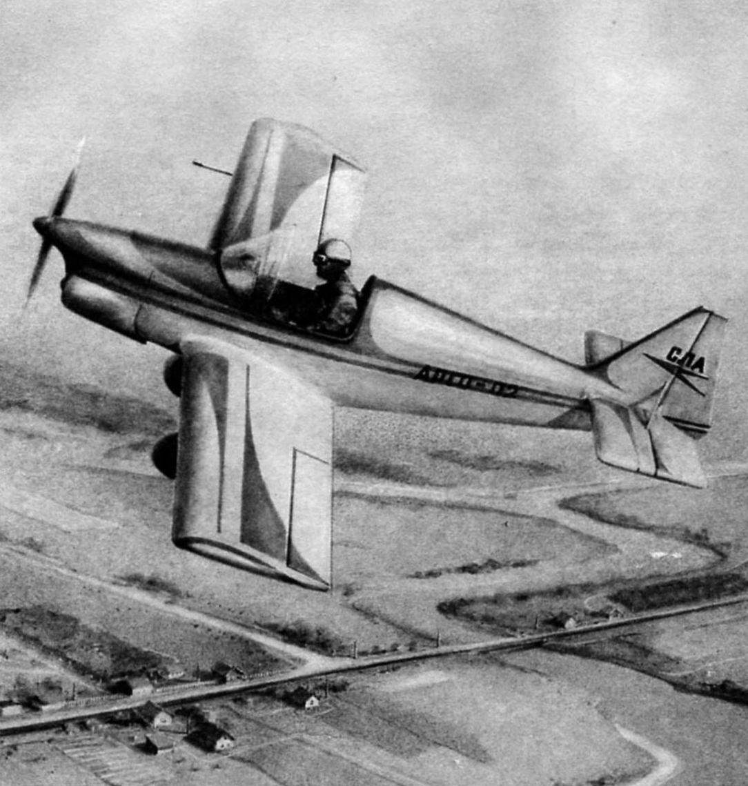
Is it possible nowadays to build your own plane? Tver aircraft enthusiasts Eugene Ignatiev, Yuri Gulak and Alexander Abramov answered this question in the affirmative, creating a winged single machine, later named “Argo-02”. The plane was successful: successfully flew on all-Union competitions, was the first winner of regional review-competition of Amateur aircraft in Yaroslavl. The secret to increased popularity of “Argo” Amateur aviators not the designer or the technological refinements of designers, but rather – their traditionalism. The designers managed to achieve a successful combination of waste over many decades of design methods of wooden cars of the 1920-ies and 1930-ies and modern aerodynamic calculations of aircraft of this class. This is perhaps one of the main advantages of the aircraft: its production does not require advanced plastics and composites, rental of high-strength metals and synthetic fabric with the pine timber, some plywood, fabric and enamel.

However, the simplest design of common materials is just one of the success factors of the machine. To all these pine slats and pieces of the plywood “flew”, they must “fit” in certain aerodynamic shape. In this case, the authors of “Argo” – to their credit – showed admirable design flair. For his plane, they chose a classical aerodynamic configuration cantilever low with the pulling air screw.
 
In our days against a variety of “ducks”, “tandem” and other wonders of modern aerodynamics the plane “Argo” looks like even the conservative. But that is the wisdom of aircraft: I would like to build a successfully flying plane -choose the classical scheme – she will never let you down.
 
But that’s not all. That plane flew well, it is necessary to correctly determine the ratio of its mass, engine power and wing area. Here, the parameters “Argo” may be considered optimal for the device with the engine power of 28 HP
If someone wants to build such a flying machine – parameters “Argo” it is possible to take a sample: this ratio provides the best performance characteristics: speed, climb, run, mileage, etc.
 
At the same time, the stability and controllability of the aircraft is determined by the ratio of the area of the wing, tail and control surfaces and their mutual location. In this area, as it turned out (which are well understood designers of Argo!), also still no one has invented anything better than the standard classic scheme. And for “Argo” parameters are taken directly from the textbook: the area of the horizontal tail is 20% of wing area, and vertical – 10%; leverage is equal to 2.5 tail aerodynamic chord of the wing and so on, without any derogation from the classical design rules, to depart from which, obviously, makes no sense.
 
Geometric scheme of the aircraft
 
The geometric configuration of the aircraft “Argo-02”
 
Aircraft
 
Aircraft:
 
1 – spinner (Vileika fiberglass); 2 – propeller (switching from pine); 3 – V-belt gear; 4 – engine RMZ-640; 5 – sub frame (tubes of steel 30KHGSA); 6 – tachometer sensor; 7 – valve; 8 – fire partition; 9 – the opening of the neck of the gas tank; 10 – compensator; 11 – fuel tank (aluminum sheet); 12 – instruments (navigation and flight control and engine performance); 13 – canopy (plexiglass); 14-crank the throttle of the carburetor of the engine (THROTTLE); 15 – control knob for roll and pitch; 16 – pilot’s seat (Vileika of fiberglass in epoxy binder); 17 – backrest; 18 – roller unit wiring control cables; 19 – intermediate rocking of the Elevator; 20 – thrust of the Elevator; 21 – hood (Vileika of fiberglass epoxy binder); 22 – fuel filter; 23 – clamping motor; 24 – suspended control pedal on the course; 25 – fixing unit spring suspension; 26 – wheel chassis 300×125 mm; 27 – spring chassis (steel 65G); 28 – filling syringe; 29 – pull Elevator control; 30 – fairing (Vileika of fiberglass epoxy binder); 31 – intermediate bellcrank Elevator control; a 32 – unit rollers control cables rudder; 33 – control cable rudder; 34 – pull Elevator control; 35 – roller unit wiring cables control the rudder; 36 – a lever of the rudder; 37 – tail prop (crutch)

 
Cabin equipment
 
Cabin equipment:
 
1 – handle; 2 – handle of the throttle of the carburetor of the engine (ORE); 3 – STANDARD; 4 – VR-10; 5 – EM; 6 – DC-250; 7 – VD-10; 8 – TE-45; 9 – shock absorber; 10-fuel tank 11 – fire hydrant; 12 – foot controls on the course

 
Control scheme
 
Control scheme:
 
1 aircraft control stick for roll and pitch; 2 – handle of the throttle of the carburetor of the engine (ORE); 3 – directions; 4 – Elevator; 5 – Aileron; 6 – foot controls on the course

 
Although aerodynamic data allow the aircraft to perform aerobatics, but aerial acrobatics is not only good aerodynamics, and high structural strength. According to the calculations of authors and technical Committee, operation overload “Argo” was equal to 3, which is sufficient to fly in a circle and short routes. Aerobatics this machine is absolutely contraindicated.
 
Amateur aircraft designers shouldn’t forget… August 18, 1990, while performing a demonstration flight at the celebration of the Day of Air Fleet, Yuriy Gulak introduced “Argo” in another coup. This time the speed was slightly above normal, and maximum operating overload, obviously, much higher than the estimated “three”. As a result, the wing “Argo” broke up in the air, and the pilot died in front of spectators.
 
Typically, these tragic cases, even with all of the obvious reasons, their causing, forced to look for errors in aircraft design and in the calculations. As for the “Argo-02”, then the car broke down exactly what was intended. That is why the technical and flight-methodical Commission on aircraft Amateur-built Ministry of aviation industry at the time recommended that “Argo-02” as a prototype for self-built.
 
“Argo-02” – an educational-training ultralight cantilever low-plan, classic wood designs with cantilever tail. The aircraft has a chassis spring type tail wheel.
 
Power plant – two-stroke 2-cylinder air-cooled engine RMZ-640, which through V-belt reducer drives the rotation of close-coupled two-bladed wooden propeller. The control system of the plane – normal type. The cockpit is equipped with instruments of the pilot group and the control devices of the engine.
 
The fuselage is wood, reconfirming construction, with spars of wooden laths with cross-section 18×18 mm. Behind the cockpit on top of fuselage – lightweight fairing, which is based on polystyrene diaphragms and stringers. The fairing is available in front of the fuselage, in front of cabin it is made of wood diaphragms and a covering of sheet duralumin with a thickness of 0.5 mm. the Cockpit and aft fuselage in the area of stabilizer attachment is sheathed with plywood with a thickness of 2.5 mm. the rest of the surface of the fuselage have a fabric covering.
 
Through the cockpit are spars of the wing, which are attached to a molded fiberglass and trimmed in faux leather the armchair pilot and post manual control of the aircraft.
The cabin inside covered with foam, and on top of it – artificial leather. On the left side set of RUD – grip throttle control of the carburetor of the engine.
 
Dashboard villacana sheet duralumin and coated with hammer enamel. In the cabin it is fixed to the frame number 3 in the dampers. On the Board mounted devices: THZ, US-250, BP-10, DC-10, ET, TE, and the ignition switch under the Board, fuel tap, front spar – filling syringe. In the front part of the fuselage under the fairing, mounted the fuel tank capacity of 15 liters
 
In the lower part of the fuselage in front of the front spar installed the attachment points of the chassis. On the front bulkhead, which is also the firewall, mounted to the node mounting of the pedal lever type and of the fixing Assembly roller and foot control. On the other side of the fire wall are non-return valve, fuel filter and drain valve.
 
Mounts engine mounts installed at the junction of the side members with the front frame. Motor mount itself is welded from hromansilevyh (30ГСА steel) pipes with a diameter 22×1 mm. the Engine is attached to Motorama through the rubber dampers. The power plant is closed the upper and lower fiberglass hoods. Billet screw glued from five pine plates with epoxy resin and, after final processing is covered in fiberglass using epoxy resin.
 
The fuselage
 
The fuselage


The base of each wing – longitudinal and transverse sets. The first consists of two spars – main and auxiliary (side), frontal stringer and rib flow. Main spar – dvupolnye, top and bottom shelves – made of pine slats of variable section. So, the cross section of the top shelf: at the root of the wing – 30×40 mm, and the end – 10×40 mm; bottom – 10×40 mm and 20×40 mm, respectively. Between the shelves in the area of the ribs sets aperture. The spar from two parties sheathed with plywood with a thickness of 1 mm; the root portion of the – plywood with a thickness of 3 mm. In the root of the wing and the mounting area of the rocking Aileron fixed wooden lugs.
 
Nodes joining the wing panels with the center section mounted in the root of the wing on the front (main) spar. They are made of steel 30KHGSA. At the end of a spar mooring site.
 
The front stringer of the frame of the wing is of wooden slats section 10×16 mm, the tail – section rail 10×30 mm.
 
From the sock to the front spar of the wing is sheathed with plywood with a thickness of 1 mm. At the root of the plywood thickness of 4 mm formed by the ladder.
 
In cross wing set includes a normal and reinforced ribs. The last (rib No. 1, No. 2 and No. 3) beamed design and consist of a shelf cross section 5×10 mm, plywood racks and wall thickness of 1 mm with holes-relief. Normal ribs are truss. They are going of the shelves and braces section 5×8 mm with rails and brackets. Wingtips -foam. After processing, they pasted the glass fiber epoxy resin.
 
Aileron – plane with a frame made of longitudinal section 10×80 mm, ribs of the plates 5 mm thick, the edges of attack and fin flow. The toe is covered with plywood with a thickness of 1 mm; together with the lining side member forms a rigid, closed profile, resembling a semicircular pipe. The hinge of the Aileron mounted on the spar, and return the hinge brackets on the rear spar of the wing. All surfaces of the Aileron and the wing covered with cloth.
Horizontal tail plane “Argo-02” consists of a stabilizer and elevators. Stabilizer dvuhkonturniy, with diagonally arranged ribs, which ensures a high torsional stiffness. Toe to the front spar covered with plywood with a thickness of 1 mm. Stabilizer can be used both in a cantilever and strut-braced version. The second option involves the installation on the rear spar of the attachment struts. The attachment points of the stabilizer to the fuselage mounted on the front and rear spars. The hinge the elevators are located on the rear stabilizer spar; their design is similar to the device nodes of the airframe A-1. Ending stabilizer foam covered with fiberglass, the Central part is covered with plywood.
 
The Elevator is in two parts, which to some extent overlap each other. Each part consists of a spar set diagonally ribs with socks and rib flow. The bow of the helm sheathed with plywood with a thickness of 1 mm. Hog steering height fixed in the root portion.
 
Vertical tail plane is a keel and rudder. The keel is structurally made integral with the fuselage dvuhlonzheronnoe scheme. Frontal part (to the front spar) covered with plywood. The rear spar is the rear bulkhead of the fuselage.
 
The rudder design is similar to the Elevator or Aileron. It also consists of a spar, straight and diagonal ribs and rib wrap. The front part of the steering wheel to the longitudinal sewn plywood. Nodes sample represent the fork bolts. The control lever is fixed at the bottom of the spar. There is mounted the attachment point of the struts. All the tail surfaces covered in fabric.
 
Main landing gear – two-wheel spring type. Curved spring steel 65G; its ends are attached to the wheels size 300×125 mm. spring Mounting to the fuselage is a steel plate and a couple bolts on each side, which spring is clamped and thereby fixed relative to the fuselage.
 
Tail wheel is a attached by two bolts to the fuselage strip of steel 65G, which is screwed to the bottom bearing Cup.
 
Fuel system of aircraft
 
The fuel system of the aircraft, “Argo-02”:
 
1 – carburetor; 2 – valve; 3 – fuel filter; 4 – feed tank; 5 – tube tank with drainage; 6 – fuel tank 7 – fire hydrant; 8 – fitting of the power supply; 9 – drain fitting; 10 – drain valve; 11 – filler syringe

 
System of receivers of air pressure
 
System receivers air pressure:
 
1 distribution of static pressure; 2 – durotomy hose; 3 – aluminum tubing; 4 – receiver air pressure (EDT)

 
The Elevator control hard using the handle (Yak-50), aluminum rods and intermediate units. Control of the ailerons are tight also. The actuator of the rudder – cable, using a suspension lever pedals, steel cables with a diameter of
 
3 mm textolite rollers with a diameter of 70 mm. to avoid getting foreign objects in the control units, the floor and the track rods and cables covered with decorative screen.
 
The power plant of the aircraft based on the engine RMZ-640 mounted on Motorama upside – down cylinders. On top of the engine, an upper pulley V-belt gear belt tension. Fiberglass hoods are attached with screws to the self-locking anchor nuts on the fuselage and the connecting ring.
 
The propeller bonded with an epoxy resin of pine plates, and then processed according to patterns, covered with fiberglass and painted. “Argo-02” was used several such screws with different diameters and pitches. One of the most acceptable for its aerodynamic qualities has the following characteristics: diameter 1450 mm, 850 mm, the chord is 100 mm, static thrust is 85 kgs. Spinner is laminated of fiberglass on epoxy binder and put on the dural ring. Mount coke to the propeller – screws.
 
Strength calculation of main components of the aircraft
 
Calculation of the strength of the major units of the aircraft
 
 
The fuel system of the aircraft consists of fuel tank capacity 14 l fuel pump, fuel filter, check valve, fire hydrant, drain, tee and piping system.
 
The fuel tank is welded from aluminum sheet with a thickness of 1.8 mm. At the bottom is a consumable container, which is welded consumables and drain fittings, top – fuel filler neck with drainage, intra – connected partitions to prevent foaming of the fuel. The tank is attached to two beams by tie ribbons with felt pads.
 
System receivers air pressure (LDPE) consists of a tube made of LDPE (Yak-18), mounted on the left wing of the plane, tube, dynamic and static pressure, the connecting rubber hoses, dispenser and devices.
 
Aircraft performance data aircraft
 
Length, m……………………………………………4,55
Height, m……………………………………………1,8
Wing span, m…………………………………..6,3
Wing area, m2………………………………6,3
The narrowing of the wing………………………………………0
End wing chord, m……………………..1,0
SAH, m………………………………………………..1,0
Wing setting angle, deg…………………..4
V-angle, degrees…………………………………………..4
The sweep angle, deg…………………….0
Wing profile……………………….R-Ø 15,5%
The area of the Aileron, m2………………………..0,375
The magnitude of the Aileron, m………………………………..1,5
 
Deflection angles of Aileron, deg.:
 
up…………………………………………………..25
down…………………………………………………….16
Wingspan, m……………………………………..1,86
Area, m2…………………………………..1,2
The setting angle, deg………………………..0
The RV area, m2……………………………….0,642
Area IN m2…………………………………0,66
Height IN m………………………………………1,0
The PH area, m2…………………………………0,38
The angle of deviation of PH, grad…………………- 25
The angle of deviation of RV, hail………………….- 25
The width of the fuselage at the cabin, m…………0,55
The height of the fuselage at the cabin, m………….0,85
The base chassis, m………………………………………2,9
Wheel track, m……………………………………1,3
 
Engine:
 
type……………………………………………RMZ-640
power, HP……………………………………..28
max. rotation frequency, Rev/min ………5500
 
Gear:
 
type………………………………..V-belt,
chetyrehluchevoy
gear ratio…………………………….0,5
straps, type…………………………………….A-710
Fuel………………………………..petrol A-76
Oil…………………………………………..MS-20
The diameter of the rotor, m…………………………………1,5
Step screw m……………………………………..0,95
Static thrust, kgf……………………………95
Weight of empty apparatus, kg…………………145
Maximum takeoff weight, kg………7235
Fuel capacity, l……………………………………15
Range
flight balance, % SAH…………24. ..27
The stall speed, km/h……………………72
Max. speed
horizontal flight, km/h……………..160
Maximum
the flying speed, km/h…………….190
Cruising speed, km/h…………………120
The speed of separation, km/h………………………….80
Landing speed, km/h……………………70
Rate of climb at ground, m/s………………2
Run, m…………………………………………….100
Mileage, m……………………………………………..80
Range
operational overloads…….+3..- 1,5

 
A. ABRAMOV, Tver

Recommend to read