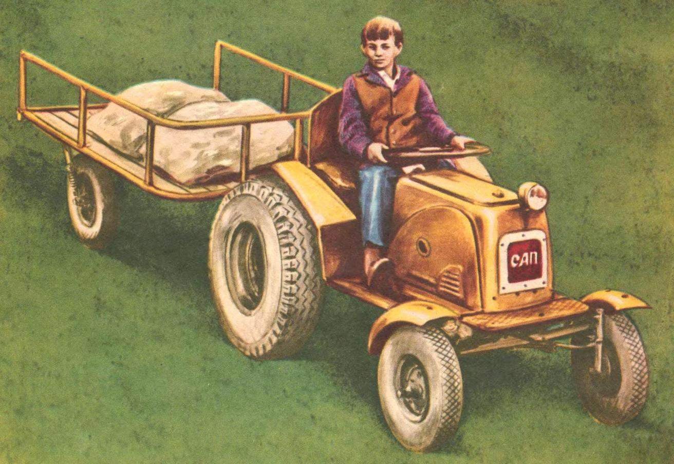
 Building a tractor-little young designers not deny myself the pleasure to use his own name initials. So there on the hood of metaphora three polished letters SAP, which means Sergei and Andrey Pavlovs. In a letter sent to the editors, they said that the big help in the development of the tractor had his father — Valery, All three regular readers of our magazine.
Our tractor (Fig. 1, 2) were designed primarily for transport purposes. It can tow a truck with a load, or a small tank with a capacity of about 100 liters to water school property or to extinguish pockets of fire along the roads.

Fig. 1. General view of microstructure SAP:
1 — the driver’s seat, 2 — unit, 3 — handle bonnet cover, a 4 — headlamp lighting, 5 — front bumper, 6 — levers gearshift and clutch control, 7 — the lever of kick starter, 8 — lever of the reverse, 9 — brake pedal 10 to the accelerator pedal.

Fig. 2. The layout of microfracture SAP:
1 — front axle 2 — elements of the frame of the scooter “Tula 200”, 3 — engine T-200, 4 — tank, 5 — steering wheel 6 — thrust reverse, 7 — attachment of rear axle, 8 — drive axle, 9 — wheel hub rear wheel with sprocket, 10 — reverse main gear, 11 — longitudinal thrust steering, 12 — the drive shaft and the node of attachment, 13 — frame microfracture, 14 — transverse thrust steering linkage, 15 — mount the engine to the frame 16 of the brake pedal 17 and the clutch shaft.
Miina proved to be very successful — she’s agile, has a high permeability. The speed is 37 km/h All speeds of the tractor eight — four forward and the same back.
And now about the device.
FRAME (Fig. 3) tractor welded. It consists of a “horseshoe”, the bent of thick-walled drill pipe with a diameter of 28 mm, the two parts of the strut and the pipe Ø 50 mm. Two steel notched plates in the rear part intended for fastening the intermediate sprockets. The use of the elements of the frame of the scooter T-200 has facilitated the installation of the engine and a portion of the lining of the hood.

Fig. 3. Frame microfracture:
1 — mount the engine, 2 — Podkova (drilling steel pipe Ø 28 mm), 3 — cross bar (angle steel 30X30 mm), 4 — bracket 5 — cross bar (angle steel 40X40 mm), 6 — figure bracket for mounting drive shaft (steel sheet S -12 mm), 7 — cross bar (steel pipe Ø 50 mm) 8 — bolt М16Х62.
FRONT AXLE (Fig. 4). Its basis is beam welded from pipe Ø 42 mm with the letter N. The place of reconciliation strengthened steel gussets. In bushings of the axles pressed bronze liners. The abutment of the front axle with the frame consists of two rails with a steel bushing between them.

Fig. 4. The design of the front of the bridge:
1 — fixing unit 2 of the front axle beam front axle, 3 — bracket, front mud flap, 4 — axle sleeve, 5 — axis, 6 — front wheel hub with brake device, 7 — pin, 8 — pivot arm
The rotary axle is turned stepped roller with welded thereto a steel sleeve (it is inserted into the front driveshaft). To the pivoting levers of a steering trapeze fitted the pedals off of a moped “Riga-3”.
STEERING (Fig. 5). The basis of it is the steering gear — gear reducer with conical gears (ratio 1:3) from a chainsaw “Friendship”. A smaller gear is connected with a steering wheel and shaft put on more potatoes, then force through a longitudinal thrust is transmitted to the lever welded to the left axle.

Fig. 5. The kinematics of steering:
1 — steering gear 2 — plow, 3 — longitudinal traction, 4 — transverse rod 5 — knuckles.
TRANSMISSION. Torque to the driving sprocket of the motor with roller chain is transmitted to the main differential gear (Fig. 6) with reversing device (motorized С3А), and then also chain to the hub mounted on the axle of the wheels.

Fig. 6. The design of the drive shaft microfracture SAP:
1 — drive shaft 2 — snap ring 3 — packing, 4 — body mounts drive shaft 5 — drive sprocket, 6 — nut, 7 — sleeve, 8 — ball bearing No. 205.
REAR AXLE (Fig. 7) is the most complex Assembly microstructure, so it makes sense to describe its design in detail. It consists mostly of parts from scrapped cars, so the main difficulty when linking the rear axle was the most successful combination.
The hub of the wheels of the car GAZ-69. For mounting them on the driven sprockets regular studs were replaced with bolts, respectively that has been modified, the seats are drive wheels. By the way, to make the rear axle more compact, we turned the inner part of the disk was external.


Fig. 7. Rear axle microfracture:
1 — axis, 2 — wheel hub (GAZ-69), 3 — wheel drive car GAZ-69 or UAZ-469). 4 — the brake drum (the motor scooter “Vyatka” EP-150), 5 — sprocket driven, 6 — plate, mounting axles, 7 — bolt with nut — fastening of the bearing housing 8 — housing, 9 — oil seal 10 — housing cover, bearing, 11 — sleeve 12 — the body of the brake pad 13 — brake pad, 14 — flange.

The device rods
Brake drums rear wheel of the scooter “EP-150”. Unlike “branded” just that they drilled five holes Ø10 mm mounting bolts to the wheel hub. The driven sprocket attached directly to the brake drums.
The body of the brake pad from scooter “Tourist”; it only enlarged the center hole to Ø52 mm and drilled three holes Ø10 mm bolt attaching it to the bearing housing. Brake pads are also used from scooter “Tourist”.
The bushing housing brake pads and the node through which the axle shaft is mounted to the frame, had to make yourself.
The most complex and critical components and parts of tractors (mainly those that were made by ourselves) are shown in the figures and drawings.

Tractor-baby, designed by students of Sergei and Andrei Pavlovym, can not only tow a two-wheeled trailer, but to plow, harrow, cultivate the soil, water and school property. In winter the front wheels are replaced with skis and the tractor turns into a snowmobile.
Currently our microtracker has passed more than 500 km without works on the schoolyard and backyards, and any accidents or even problems was not. To microfracture made two-wheeled trailer and plow, paired with which SAP works very satisfactorily. Now we are trying to adapt to it screws.
The tractor has good permeability not only in summer but also in winter. Its front wheels are replaced by skis. The same operation can be subjected to and the trailer — two-wheeled cart.
The editorial staff receives dozens of letters, which somehow addresses the issues of Amateur “tractor”. Some requests for consultations (“where to get” “how to do”, “where can I get blueprints”), while others talk about a homemade tractor built by students and adults. Apparently, it is possible to draw some conclusions.


