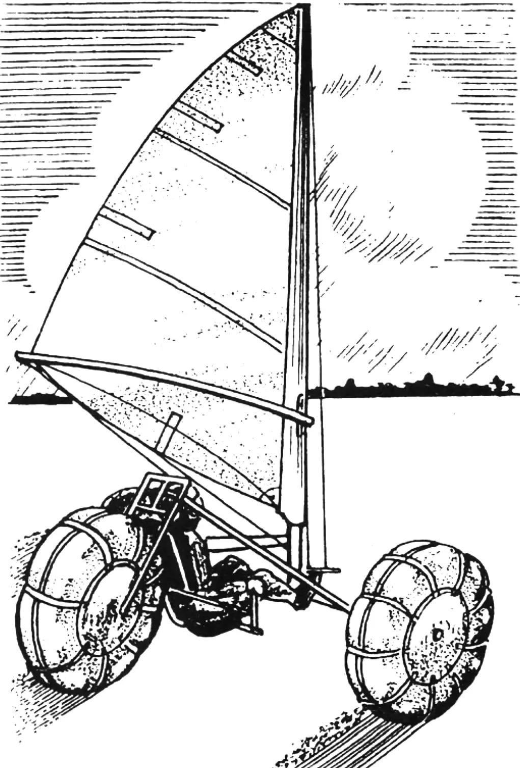
Over the past decade, motor all-terrain vehicles on light wheels with pneumatic inner tubes have become especially popular among amateur designers. The remarkable cross-country ability of such machines prompted sailing sports enthusiasts to use the unique properties of the pneumatic wheel when creating all-season sail craft.
This publication introduces readers to such a vehicle.
So, let’s get to work. We advise starting with the most difficult part — making the running chassis.
The chassis frame is welded from thin-walled steel tubes. To make the frame symmetrical and free of distortion, it makes sense to set up a kind of assembly jig for putting it together. In the simplest case, this is a level section of floor on which the front axle and the rear steerable fork together with the steering column are mounted according to the chassis dimensions.
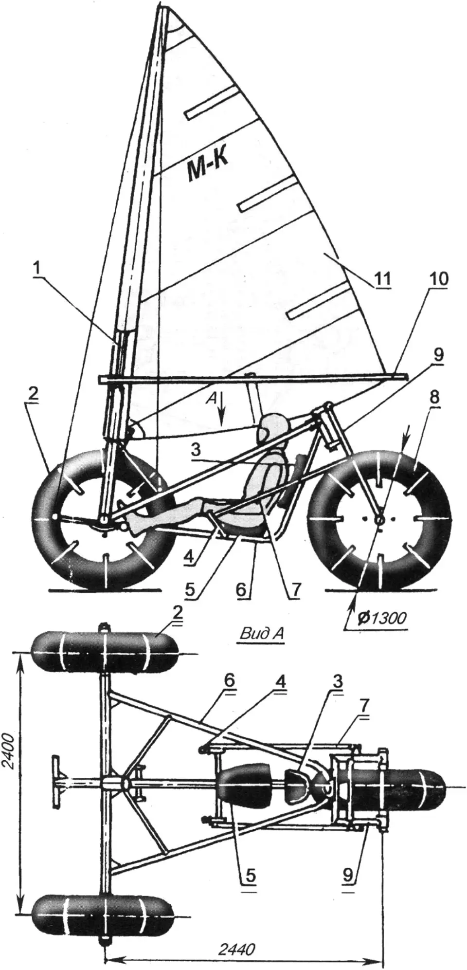
1 — mast; 2 — front wheels; 3 — backrest; 4 — steering arms; 5 — seat; 6 — frame; 7 — steering rod; 8 — rear wheel, steerable; 9 — rear wheel fork; 10 — boom wishbone; 11 — sail
The next stage is making and fitting the central frame beam. This part has a curved shape, so you will need to use a tube bender. It is advisable to heat the bend area with a gas torch or blowtorch, which will help avoid dents and corrugations. The tube is then fitted to the front axle and steering column and tack-welded to them at several points.
Now you need to prepare for assembly the tube part bent into a “V” shape, forming the side frame beams. All welds are finished only after a thorough check of the correct fit of the frame elements.
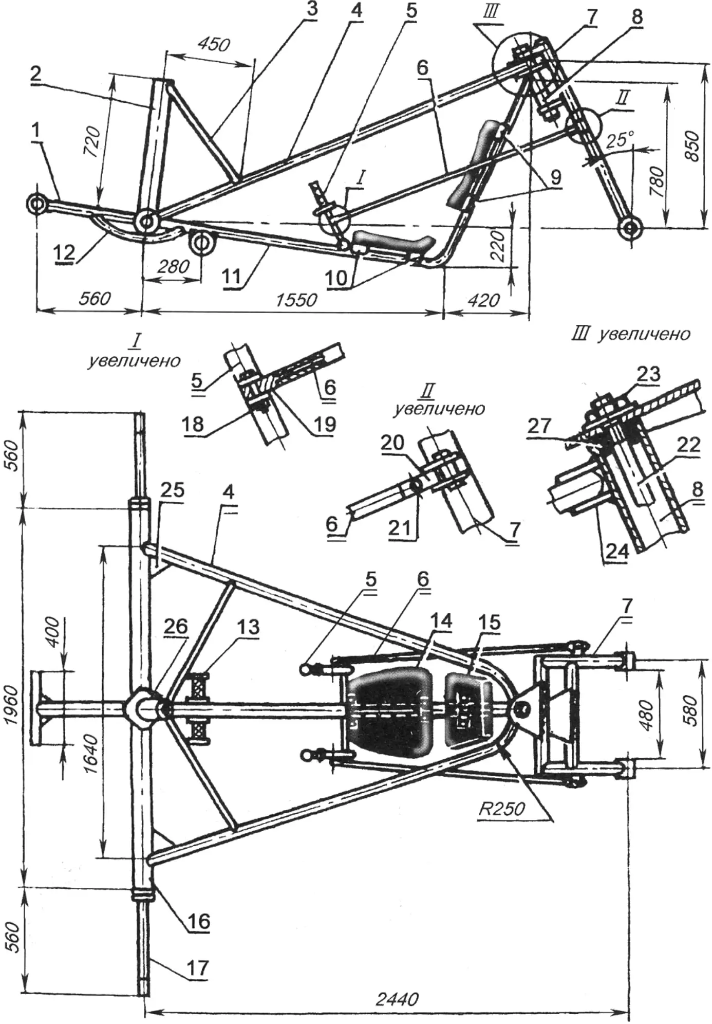
1 — bowsprit (tube 30×2); 2 — mast step (tube 60×2.5); 3 — brace (tube 20×2.5); 4 — upper frame belt (tube 30×2); 5 — steering arms (tube 22×2.5); 6 — steering rods (tube 16×2); 7 — rear wheel fork; 8 — steering column (tube 36×2.5); 9 — backrest mounting brackets (strip 4×40); 10 — seat mounting brackets (strip 4×40); 11 — central beam (tube 30×2.5); 12 — cross member (tube 22×2.5); 13 — footrest (tube 22×2.5); 14 — seat (plywood, foam rubber and artificial leather); 15 — backrest (plywood, foam rubber and artificial leather); 16 — front beam (tube 36×2.5); 17 — half-axle; 18 — M6 bolt with nut and washer; 19 — steering rod end; 20 — double-hinged fork (sheet s3); 21 — fork axle, horizontal (M6 screw with nut and washer); 22 — M12 stud of steering column hinge; 23 — M12 nut with washer; 24 — reinforcing gusset (sheet s2.5); 25 — angle gusset (sheet s3); 26 — central gusset (sheet s3); 27 — bushing (bronze, textolite or PTFE)
Next, a mast step is attached to the central frame tube at the point where it joins the front axle — a thin-walled steel tube whose inner diameter is slightly larger than the outer diameter of the mast.
A few words about the rear steerable fork. As can be seen in the drawings, it is welded from steel tubes — two blades and two cross members. Triangular steel plates, called bridges, are welded to the latter: they connect the fork to the steering column.
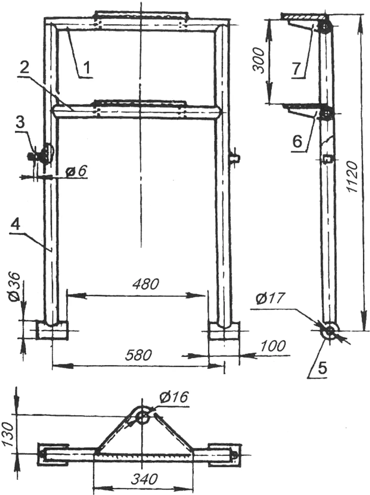
1 — upper cross member (tube 30×2.5); 2 — lower cross member (tube 30×2.5); 3 — gib (square 16); 4 — blade (tube 30×2.5); 5 — bushing; 6 — lower bridge (sheet s2.5); 7 — upper bridge (sheet s2.5)
We will begin making the sail with cutting the panels. First, you should mark out the main triangle on a level floor, or on several sheets of plywood, or even on an asphalt area, and then, having set off the “roaches” on the leech and foot of the sail, draw smooth curves similar to those shown in the drawing.
The next job is marking the seams. The line of the first seam is drawn from the tack (forward lower) corner of the sail, perpendicular to the rear line of the main triangle. The remaining seams are marked parallel to the first, with a spacing corresponding to the width of the fabric you have.
After sewing the panels together, the sail is trimmed along the leech, luff and foot, and batten pockets are sewn on for the elastic elements — battens that support the leech and foot.
Finishing the leech and foot is done with tape — synthetic or cotton. The latter only needs to be pre-shrunk — soaked, dried and ironed.
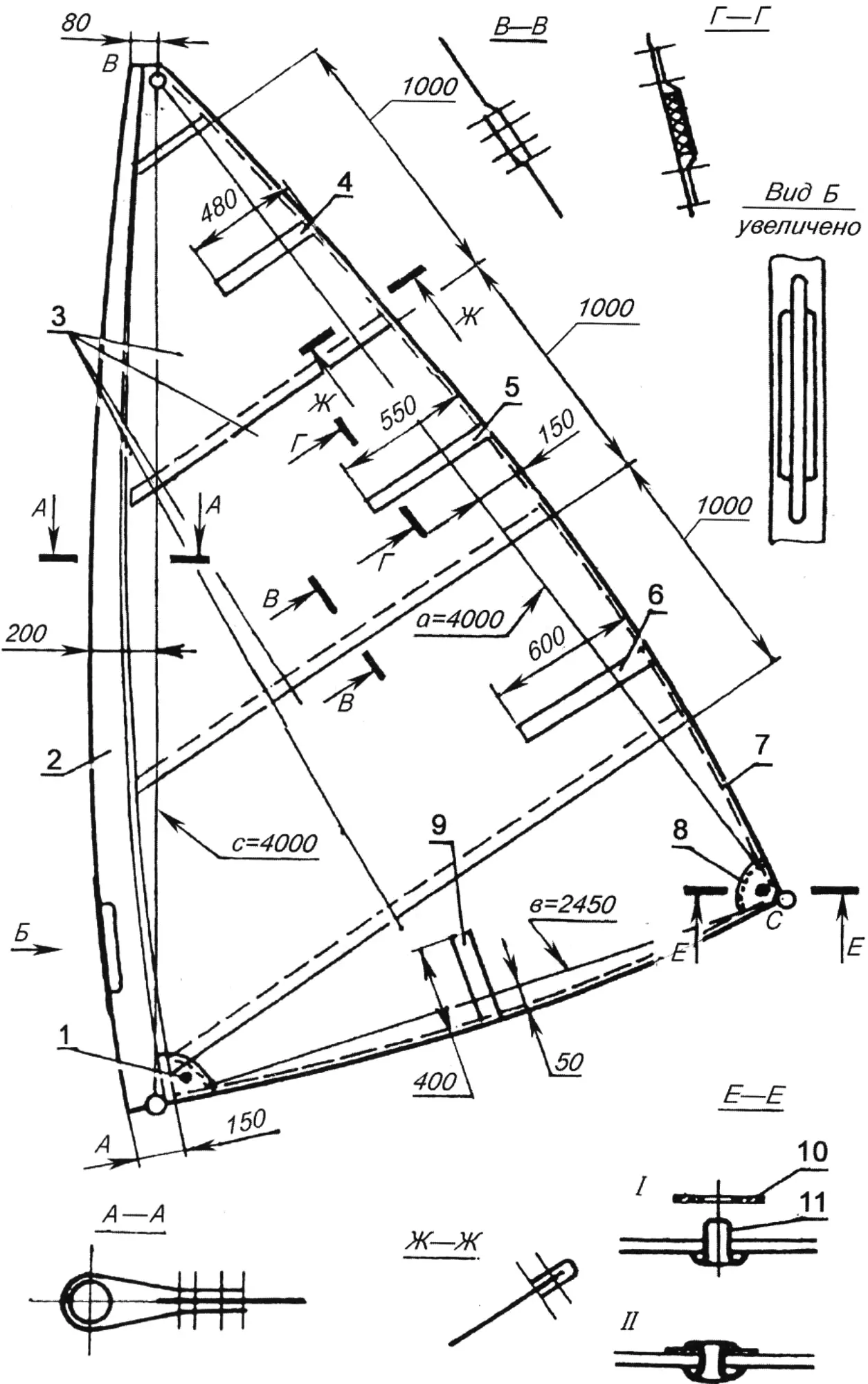
1,8 — grommets; 2 — mast pocket; 3 — sail panels (the drawing shows a version with panels 1100 mm wide); 4,5,6,9 — batten pockets; 7 — leech; 10 — grommet washer; 11 — grommet eyelet (I and II — stages of grommet installation)
To secure the sail on the mast, a so-called mast pocket is provided — a strip of fabric folded double and stitched to the luff of the sail. A grommet — a brass sleeve for the sail ties — is fastened in each of the clew and tack corners.
The sail craft mast can quite well be shaped from quality pine timber or from laminations of straight-grained boards about 10 mm thick. The wooden mast should be tapered: at the top its diameter is about 30 mm, at the bottom — 55 mm.
And the last rigging part is the boom wishbone, resembling two bows folded together. It is easiest to make it from a 22 mm duralumin tube; a half-cleat of wood or textolite is attached to its forward part.
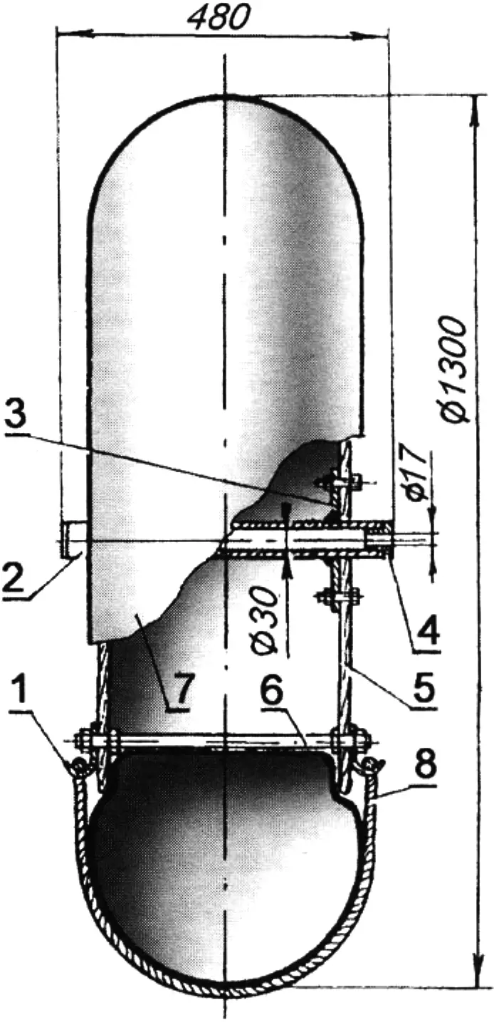
1 — clamp for securing nylon rope; 2 — central hub (tube 36×3); 3 — flange (sheet s2.5); 4 — bushing (bronze, textolite or PTFE); 5 — cheek (plywood s10…12); 6 — M12 stud with four nuts and washers; 7 — pneumatic (inner tube from a truck tire); 8 — rope or belt (nylon)
The wheel pneumatics are made from truck inner tubes. Depending on their geometric parameters, the wheel hub dimensions are also chosen. Each hub consists of bushings — sections of steel tube with flanges welded to them and bronze or PTFE liners pressed into them.
The wheel discs are cut from plywood about 12 mm thick; they are secured on the hub with M6 bolts and nuts, and connected to each other with long steel threaded studs, nuts and washers.
The front wheels rotate on half-axles — steel threaded studs fastened to the front frame beam.
“Modelist-Konstruktor” No. 2’2011, I. SERGEEV
Recommend to read
 ANTENNA UHF
For sure the television reception in the range of decimeter waves, recommend using double spiral antenna, the production of which under force even to the beginner. With linear... KMD IN RADIOLARIAN
When designing the model of the catamaran, calculated under domestic motor KMD-2,5, revealed the need to adjust speed on the radio. Had to carve out two parts aluminum diffuser carb...
