Security systems are a rapidly developing area of modern electronics. A huge number of various circuits and designs have been published that anyone who has held a soldering iron in their hands at least a couple of times can build. For example, “electronic guards” can warn of an intruder entering a room or signal the presence of a nearby voice recorder used for unauthorized audio recording.
Often, the mere blinking of LEDs and the alarm signals of buzzers accompanying the operation of the electronics can scare off an intruder.
Such devices are extremely simple to make. Using miniature reed switches, even a beginner radio amateur can solder a whole set of “electronic guard” devices. In several examples, we will describe what the circuit of each device should be, what the manufacturing technology of such devices is, and even how to monitor the operation of security electronics using Internet technologies.
Reed switches are the commonly used short name for hermetically sealed contacts. In essence, they are the same as relays, but without an armature and mechanical linkage to the contacts. The reed switch contacts are enclosed in a sealed housing and close when exposed to a magnetic field (for example, from a permanent magnet). Reed switches of various sizes and operating characteristics are available for sale; they are divided into three main types: make, changeover, and break reed switches. The circuits below use only make reed switches with normally open contacts.
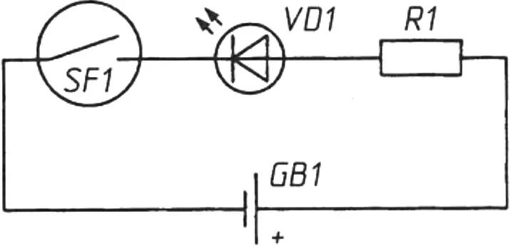
Let us consider the simplest magnetic field indicator circuit, which can be used to detect voice recorders with a miniature speaker (Fig. 1). The operating principle of the device is extremely simple: when the indicator is brought close to a voice recorder, the speaker magnet closes the contacts of reed switch SF1 and the signal LED lights up. To make such an indicator, you can take LED VD1 with a supply voltage of 3 V and battery GB1 of type CR2025 or CR2032, also rated for 3 V. In this case, resistor R1 can be omitted from the circuit. With a higher supply voltage, the resistor will be necessary, and its value is easily calculated using Ohm’s law for a section of the circuit. Any miniature reed switches can be used in the indicator.
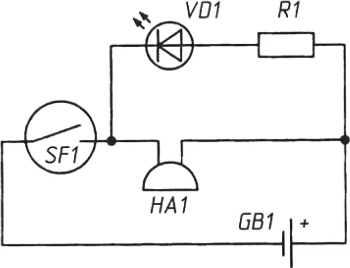
This device can be made more “respectable” by adding just one element — buzzer HA1 rated for 3 V. Indeed, by connecting a buzzer in parallel with the LED (Fig. 2), we get a magnetic field indicator that, when triggered, not only lights the LED but also produces an audible signal.
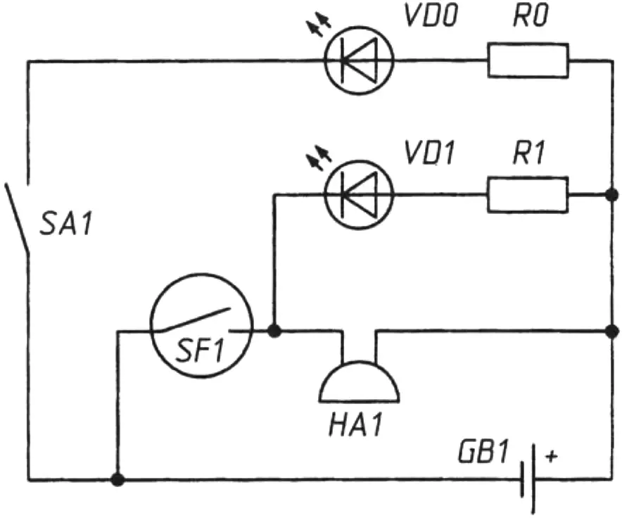
Before using the indicator, it is useful to make sure the battery is working. Let us modify the circuit once again by connecting LED VD0 and single-pole switch SA1 as shown in Fig. 3. In this case, when the switch contacts are closed, LED VD0 will always be lit, indicating that the power source is in good condition.
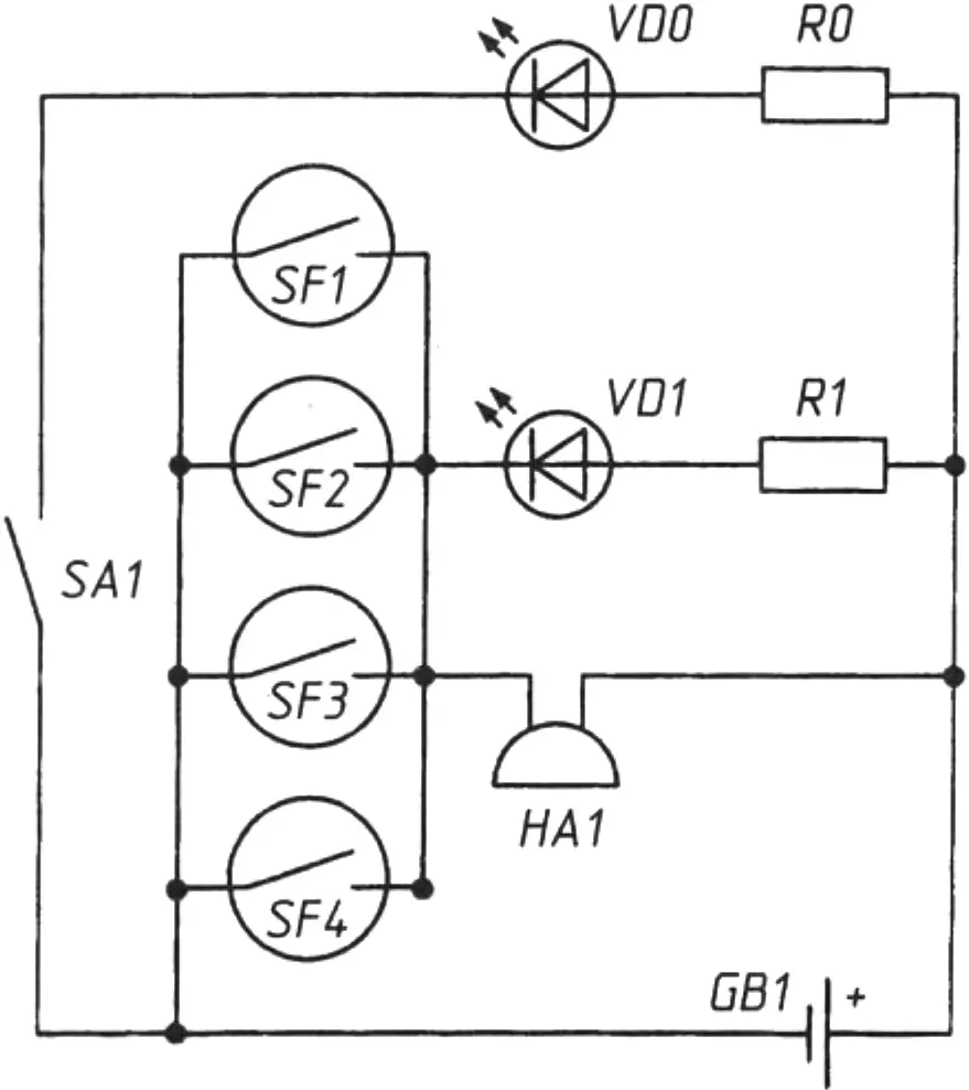
Is such a device reliable in operation? Yes, if the reed switch is brought close enough to the speaker (a voice recorder with a speaker). Unfortunately, the reed switch contacts may fail to close if it is installed at an angle. A more reliable device is the one whose circuit is shown in Fig. 4. Here, four reed switches SF1–SF4 are connected in parallel and can initially be installed at different angles to the magnetic field source. Thus, the probability that at least one reed switch will operate will be higher, and the indicator will become more sensitive.
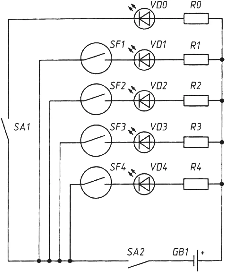
Based on the same principles, you can create the simplest security system to protect rooms from uninvited guests. Its circuit is shown in Fig. 5. In this case, reed switches are installed on doors and windows so that each one initially fits tightly against a small magnet. For example, a reed switch can be installed on the front door, and the magnet adjacent to it — nearby, on the door frame. When the door is closed, the reed switch contacts will be closed, and the LED of the corresponding security line will be lit. As soon as an intruder opens the door, the LED will immediately go out, signaling a break in the electrical circuit.
It is interesting that even such a simple security system can prove quite effective if used together with Internet technologies. A personal computer and a webcam will help you monitor the integrity of the room every second from any geographic location, simultaneously recording the status of doors and windows. It is enough to point the webcam at the control panel with signal LEDs. Even greater capabilities are provided by using computer programs such as the freely distributed Easy Free Web Cam. It is claimed that with this program, the camera can also be used as a security system with a motion sensor. As soon as the program detects a change in the image within the frame, the camera will start recording, automatically upload the image to the specified server, and, to top it off, terrify the intruder by playing dog barking through the speakers. The program allows you to adjust the accuracy of detecting moving objects in the frame.
In general, if you show a little ingenuity, you can come up with many interesting security circuits using reed switches. In particular, you can make a code lock that operates only when reed switches and magnets are arranged in a strictly defined position to close the contacts, and much more. Let us briefly stop at how to make simple printed circuit boards for such designs. As a rule, using printed circuit boards makes it possible to reduce the overall dimensions of electronic devices and improve the reliability of their operation. In printed mounting, connections between components are made using thin flat conductors applied (as if “printed”) to the board.
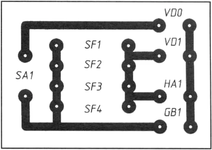
The blank for a printed circuit board is usually getinax or fiberglass with a thin copper foil glued to it. The pattern of the printed circuit board is applied to the foil surface with varnish (nail polish can be used). After the varnish dries, the board is immersed for etching in a ferric chloride solution. By periodically shaking the container with the board, its uniform washing with the solution is ensured. During etching, the foil areas under the varnish layer will remain untouched, while in other places the copper foil will be removed (etched away). Next, the board must be rinsed with running water, dried, and the varnish removed with a swab and solvent. A pattern of thin copper conductors will remain on the board surface. Holes 0.8–1.5 mm in diameter are drilled in the places where components will be installed. The appearance of the printed circuit board for a four-reed-switch magnetic field indicator is shown full size in Fig. 6. After soldering the components, it is advisable to coat all connection points with colored transparent varnish or shellac. On the one hand, this protects the solder joints from environmental effects (adverse atmospheric and climatic conditions); on the other, it gives the printed circuit board a finished look with all the attributes of industrial design.
«Modelist-Konstruktor» No. 12’2011, A. ZLOBIN
Recommend to read
 AND NIGHT — DAY
On the Parking of campers and motorcyclists will be useful to fluorescent. It gives good coverage and is very economical. As power supply used by the DC / DC Converter transistor type... “Little Donkey” wants to go on a hike
Over the years of being passionate about water tourism, we have tried several variants of carts for transporting kayaks and equipment. And on hikes, we have seen many different portable...
