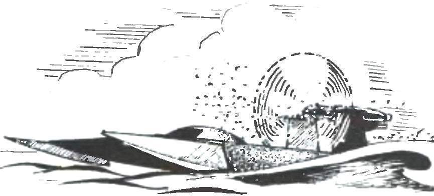
 Racing airboat engine “Raluka-7”. The journal “modelist-Konstruktor” has repeatedly told on the pages of the increasingly popular class of radio controlled racing boat with aerodiesel. Is there any need to remind them of the case differ from those created for similar models with the propeller, except that greater width, however, the design of the power unit with the propeller not in the example easier. So, for aerolister not required technologically sophisticated gear reducer, it does not need water-cooling system motor and transmission drive propeller. All this greatly facilitates the work over the model and, consequently, makes it available for production, even for novice athletes.
Popularization in the journal “modelist-Konstruktor” RC aerovision eventually began to bear fruit in some regions of Russia competed racing aerovision (up to regional). Increased and the flow of letters to the editor — many of them readers asked about racing the boat with the engines of large cubic capacity — type “Raduga-7” or O. S. MAX-40LA. The fact that one of the components of fuel for compression engines of small categories is the ether, which in recent years has almost disappeared from the chemists’, but methanol is the main component of fuel for engines with glow ignition — has become much more accessible.
In our today’s publication, we offer readers such a radio-controlled airboat.
To begin with some recommendations that must be followed when constructing a boat of this type. In contrast to the classical boat with the propeller at speed which mostly is affected by the hydrodynamics, the development of aerolister to take into account the aerodynamics of the model.
Maximizing the propeller thrust is impossible without competent organization of air flow before the air screw, and for him. In particular, the contours of the front of aerolizer should not have projections and sharp bends in surfaces that can cause disruption of the laminar flow of the incoming air flow. Somewhat more complicated is the case with the rear part of the model — here, the air flow into the engine and the pylon on which it is installed, the muffler and fuel tank. All these elements should be put together so as not to “lock” them air flow — in this case, the propeller thrust and thus the speed of aerolister can be reduced significantly.
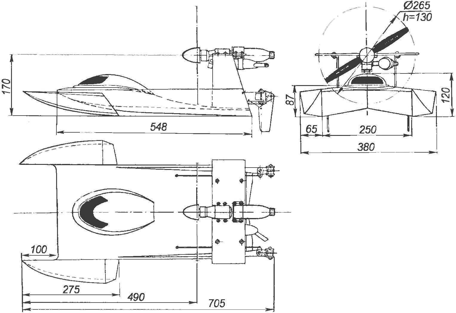
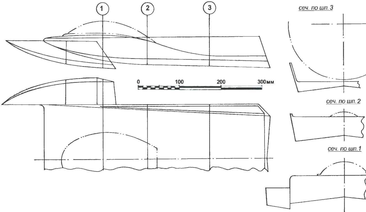
Geometry racing model aerolaser
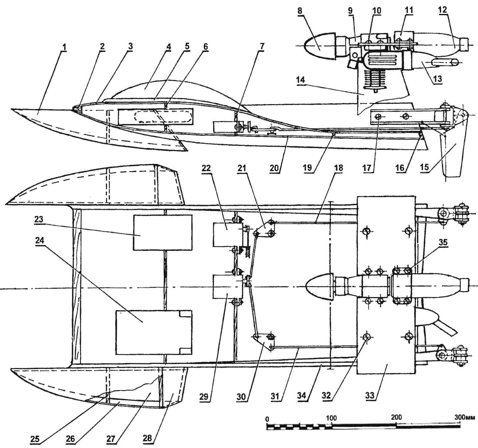
The layout of aerolister (planned projection deck and no light shown):
1 — internal forces and the lateral wall of the float (plywood s3); 2 — front cross member (pine, rail 10×15); 3— deck sheathing (plywood s1); 4 — light; 5 — edging lamp (plywood s3); 6 — frame No. 1 (Linden, plate s5); 7 — frame № 2 (Linden, plate s5); 8 — spinner; 9 — engine “rainbow-7”; 10 — motor mount (screws with M3 nuts and split lock washers); 11 — clamp fuel tank (aluminum, sheet s1); 12 — fuel tank (spray can with a capacity of 150 — 200 ml); 13 — silencer; 14 — vertical uprights of the pylon mounting the engine (aluminum, sheet s3); 15 — steering device; 16 — transom (Linden, plate s5); 17 —mounting the steering device (self-tapping screw Ø4); 18,31 — rod steering (dural needle 03); 19 — frame № 3 (Linden, plate s5); 20 — hull bottom (plywood s1); 21,30 — steering levers (aluminum, sheet s3); 22,29 — servos; 23 — the battery pack; 24 receiver; 25 — frame float (plywood s3); 26 — side wall of the float (plywood s1); 27 — the bottom (plywood s1); 28 — transom (plywood s3); 32 — mount “wing” (M3 screw with nut and split washer); 33 — “wing” (made of anodized aluminum, sheet s3); 34 — side panel (Linden, plate s5); 35 — a bolt with M3 nut
Another problem associated with the power plant. The fact that high quite heavy engine makes the boat walkem, unstable on bends, so the elaboration of the layout of the model should be placed, if possible, below. For example, as shown on the drawings.
Work on making aerolizer best to start with the hull. His frame going from the front cross member (pine rake), a pair of sidewalls, three frames and transom planks (lime plate thickness of 5 mm) and is sheathed with plywood with a thickness of 1 mm. it should be noted that the sides of the body twisted in the longitudinal direction to obtain such a twist, billet steamed in hot water and then fixed in the simplest slipway to dry wood. In the manufacture of housing frames to provide openings, scuppers, and in the back — hole, plugged with a plastic tube: if water will penetrate into the cavity of the bridge through these openings it will be easy to remove.
The front of the deck plating is cut, oval, hole — hatch for access to the remote control equipment. The hatch is light, stamped out of tinted plastic and is contoured flange from a 3 mm plywood. By the way, the plastic preform is best to use a conventional two-liter bottle of carbonated water — her smooth cylindrical part expanded in the plane.
Before installing the deck in the hull are fixed with lodgements for two servos (control the “gas” and rudders), receiver and battery pack. The location of these elements should provide their installation in the hull and quick replacement through the oval hatch in the deck.
The basis for each of the side floats are wall, transom Board and the sole frame (plywood with a thickness of 3 mm). Sheathing — plywood with a thickness of 1 mm; the connecting plates on the outer contour is made using pine stringers. During Assembly it is best to use epoxy glue; before installing the last sheet, the plating floats inside should be covered with the same glue, slightly diluted with acetone, it will make them more waterproof. By the way, the same way it is necessary to seal the shell of aerolister. And yet, in the frames of the floats, in the same way as in the frames of the hull, you must cut holes for the scuppers and transom parts — water drain hole is plugged with a plastic plug.
The docking of the side floats and the hull is made by a pair of screws with nuts; on the stage of debugging aerolizer makes sense to consolidate each of the floats only one screw, and only after the selection of the angle of their installation relative to the housing in the process of running tests to fix the second screw In the rear of the chassis is mounted dvuhmetrovoe steering device consisting of a pair of steering brackets (dural channel) and two ball-lerov with feathers. The latter should be cut from the wafer, glued from four layers of plywood with a thickness of 4 mm, and then to give them a symmetrical lenticular profile. Right and left spindles are controlled by longitudinal rods, which with the help of the l-shaped levers duplica transverse rods connected with the steering machine.
The engines of the “rainbow-7” with a staff of a tractor propeller with a diameter of 265 mm (step — 130 mm) is installed on the aluminum pole, which is a kind of wing mounted on two vertical posts. On the same wing with a cable tie secured the fuel tank to make it of aluminium aerosol container outside diameter of about 40 — 50 mm; its capacity should be 150 — 200 ml. the Control of “gas” is steering the car using rope in budenovskoy shell.
The theoretical drawing of the hull of aerolister
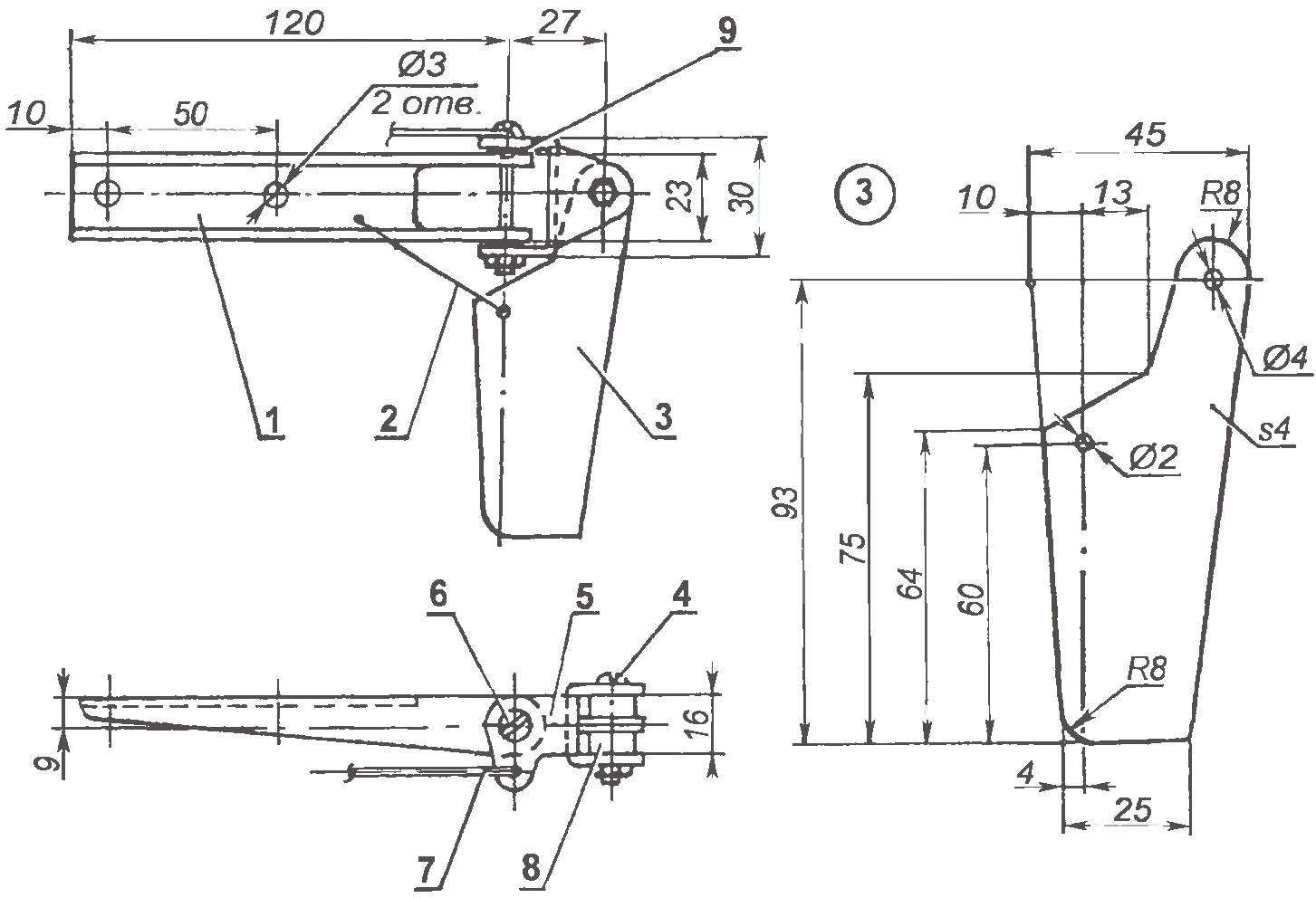
Steering gear:
1 — bracket (made of anodized aluminum, the channel 23x16x2); 2 — quickdraw (model aircraft rubber); 3 — steering pen (plate of four layers of 1 mm plywood); 4 — axis steering of a feather (M3 bolt with nut and spring washer split); 5 — shaft (duralumin, sheet s2); 6 – the hinge shaft (M3 bolt with nut and spring washer, split); 7 — longitudinal steering rod (dural needle Ø3); 8 — bushing (PTFE); 9 — washer
The process first starts, you should set the axis of the screw thus to partially compensate for the torque of the engine that deploys the airboat. A good method to counter torque is to install uprights of the pylon mounting the engine at an angle 3 to 5 degrees so that the airflow rejected an airboat to the right.
By the way, the design of the pylon is a good straightener, stabilizing the air flow from the propeller aerolizer.
In conclusion, I would like to quote from letters to a longtime reader of the magazine “modelist-Konstruktor” and an active enthusiast of aircraft and ship modeling A. I.Bokova from the village Mikhailovka, Kursk region, which in recent times actively builds and promotes aerolizer and performs with them at the regional competitions: “We successfully held competitions modelers on aerolister in the form AA:
— the stage “D” — racing at maximum range, walkable model, in 3 minutes from one buoy to another, located at a distance of 50 m;
— the phase “C” race at the maximum speed developed by the model at the same distance that the model must pass 4 times; winner is the athlete whose model is 4 laps in minimum time;
— stage MB — sea battle, during which the athlete must hit a steel needle, mounted on the nose of the model, for no more than 3 minutes at least three balloons, manufactured by waters; the winner is the one who will do the exercise for the minimum time;
— stage G — the most exciting and interesting when the waters start several models with the objective to show the minimum passage time of the ten laps from one buoy to the other.”
I. TEREKHOV
Recommend to read
 “PANTHER HUNTER”
Shortly after the outbreak of the Second world war, the Germans faced a serious crisis in the anti-tank artillery. Their primary 37-mm gun Cancer 35/36 was completely powerless against... RADIOSONIC CONTROLS THE PUMP
The creation of remote electronic devices control various actuators were promising direction in the radio even during my "pioneer" childhood in the 1980-ies. Then, under the guidance of...
