Next, the billet is marked with the aid of a planning template, which can be fixed with a small nail in the center of the future screw with a pencil, after which the template is rotated 180° and is marked with the planned projection of the second blade. The excess wood is removed chorus or band saw with fine teeth.
The most critical part of the work — giving the airfoil blades. As can be seen from the drawing of the screw, one side flat and the other convex. In accordance with the position of the reference cross sections on the workpiece and mark the location of the templates, and semicircular semicircular a chisel and a rasp break “beacons” in accordance with the configuration of the upper and lower templates.
The main tool for handling rotor blades of a small axe from a good steel, sharpened literally to the sharpness of the razor. When you remove wood it is recommended to do a small notesy — this will prevent splitting of the workpiece. Followed by pre-treatment of the workpiece with a plane and rasp.
Followed by final finishing in the stocks. The latter is a carefully ottogo-the bathroom Board with a minimum thickness of 60 mm, which are made lateral cuts to a depth of 20 mm for installation in them of lower templates of the rotor blade profile. The Central core of the bench is machined from steel, or duralumin, its diameter should fit the hole in the propeller hub. The rod is glued in the center of the stacker Board perpendicular to its surface.
Further working surfaces of the lower patterns are rubbed with colored pencil or methylene blue, billet screw fits over the Central rod and pressed against the templates — first one blade and then another. In this case, the workpiece is imprinted the traces of the templates in those places where they come into contact with the lower surface of the propeller. “Dirty” places with the help of a planer, plow, rasp or a piece of wood glued to it with sandpaper, clean off, the workpiece is again placed in the stocks and treatment of the blades is repeated. When traces of colored pencil will be imprinted over the entire width of the blade, machining the bottom surface can be considered finished.
The upper part of the screw is processed in the stocks by using the top templates (also called contrabanda). First with a semi-circular rasp blade is fitted to contraband (as the professionals put kontrabandy), causing the template and contraban should be in contact at the plane of the connector, tightly covering with this very blade. Then treated areas are rubbed with a crayon and processed zone between the test sections. In this case, the coloring is necessary in order to eliminate double handling of the blade at the locations of the control sections. The correct treatment checks are made to ensure smooth steel ruler, apply to the one percent points of the neighboring sections. On a properly made blade clearance between the line and the surface should not be.
If in the process of work awkward movement of the tool led to chipping of the wood, this does not mean that the work is spoiled. Fix it with putty, mixed with epoxy glue and fine sawdust.
The finished screw is carefully balanced. This is best done, by inserting tightly in the Central hole of the metal roller and installing the propeller on the balancing line. If one of the blades will be easier, it is recommended to load lead for the first glued small strips of this metal, and when the propeller is balanced, the strips are melted and poured into a mold, for example, in a section of steel pipe. The resulting rod (or rods) vkladyvayasj in a hole drilled in the wrong place of the blade, where the pasted strips of lead. Hole on both sides of the blade should be lightly razzenkovku.
Finish propeller is pasting two layers of thin glass, followed by grinding, final balancing, primer and paint topcoats.
Housing aerolizer consists of two major parts — upper and lower. Assembly it is best to start from the bottom. To do this, in accordance with theoretical drawing of the hull and drawings of plywood with thickness of 12 mm are cut forming the frames and rails with cross-section 20×20, 30×20 and 30×30 mm — stringers and keels. The frame is assembled on a level floor. Previously on it are laid out diametrically plane and the location of the frames. The frames are fastened to the floor using wooden sticks and strips-braces. Adjustment of the longitudinal rails set in place, fastening the rails to the frames with epoxy glue with temporary fixation elements for locking wire. The curved rails for the front part of the frame obtained by pre-steaming them in boiling water and fixing the wire on the frame. After drying, strips the latter are fixed to the frames with epoxy glue.
After malkivka (alignment) frame specii filled with blocks of construction foam that are captured using the same epoxy resin. After treatment of the foam surface (if necessary, it podsalivaya the familiar composition of epoxy glue and sawdust) housing glued with two layers of fiberglass, puttied, sanded and painted with enamels. Inside the foam is cut flush with the frames and also glued with fiberglass.
The theoretical drawing of the lower shell.
The design of the frame the bottom of the hull.
The manufacture of the body:
A — frame Assembly; B— filling space foam blocks; – covering of the hull with fiberglass
The design of the frame upper part of the body.
Propeller.
Section of the billet air screw (a — billet-monoblock; — procurement glued).
Pre-treatment of the propeller:
A — marking of the workpiece with a template of the side view; B — the markup using the standard template; In — depth “beacons” to rough cutting of the blades; G — processing of the blades of a plane; D – processing a rasp and sandpaper
V-belt drive power unit of aerolister:
1 — bolt M10; 2 — washer; 3 — the screw of the air; 4,17 — bolts M8; 5 — lock washer; 6,7 — bearings 204; 8 — axis console; 9,10 — sleeve remote; 11 — 205 bearing; 12 — a remote washer; 13 — a lock ring; 14 — nut M8; 15—a bolt mechanism for the belt tensioning; 16 — a pulley driven; 18 — transitional bushing, 19 — bracket reducer (2 PCs); 20 — V-belt (4pcs); 21 —pulley leading; 22 — rivet d5 (steel, 10 PCs.); 23 — plate-spacer; 24 — engine “Whirlwind-30”.
The slipway for final processing of the propeller (0-6 — bottom templates control sections).
Control of the correct processing of the propeller in the stocks with templates and contraband:
1 — Central rod; 2 – the screw of the air; 3,4 — contraban; 5 — Board stacker; 6 — lower templates.
Under engine frame (welded rectangular pipe section 30x24x2,5; ears, engine mounts and struts are welded in place).
Top manufacturer of aerolister differs little from the bottom. However, the frame is assembled not from plywood frames, and harvested curved slats and not on the floor and ready the bottom of the hull.
The frame on which the engine mount attaches the engine has an increased cross-section and reinforcement in the joints of the rails — plywood gusset plate. The frame itself is fastened to the crossmember of the square steel tube cross-section 40×40 mm and is fixed by struts of pipes with a diameter of 22 mm.
Shaping is also performed with the help of the foam with subsequent covering with fiberglass.
Glass door — Plexiglas 4 mm thick, and windshield glass from a rear door of the car “Moskvich-2141”. The door itself was part of the cabin.
Door aerolizer consist of a wooden frame and plywood sheathing. Inside and outside they are covered with fiberglass. Door hinges — home-made, overhead. In the ceiling of the cabin (or if you want logging) is removable manhole cover, manufactured from the cut part of the roof.
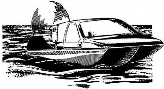
At the rear of aerolister installed two keel that organize air flow and also performing the function of the fence propeller.
The airboat is controlled through the steering wheel, the shaft of which is secured to steering drum associated with the cable runs traverse on ballerinas steering box. Management of the “gas” lever located under the left hand of the driver.
In the cabin are seats for passengers and driver. Seat frames and backs are glued together from wooden slats and sheathed 4 mm plywood. Cushion — foam and artificial leather.
I. KHOROSHEVSKAYA
Recommend to read URAL VS “RHEINMETALL” The victory of the Soviet troops in the forty-second and forty-third years had tipped the scales of war in our favor. The enemy got an object lesson. Failing two consecutive critical... PIPE — HAMMER There are cases when after oblique impact arm break in two next to the hammer, resulting in not only loss of the tool or of the workpiece, but also serious injury. To avoid this... 
 The propeller, or, as at the dawn of aviation, the propeller is experiencing a rebirth. The reason is the emergence of daltelecom and motor paragliders with very advanced rotor settings. The pilots quickly learned that they can be used in ground form.