
 Winter in our Northern lands long. Roads are not so thick, and those on time do not have time to remove snow from. It turns out that no trails of cars people here do not easy, moreover, often have to travel entirely off-road (e.g. forest wood) — recorded directly on virgin soil. However, the acquisition of a snowmobile, not everyone can afford, even the not-so-expensive—simple. So we have those who are able to make a machine with their hands, designing it according to your project under those parts that the craftsman. The snowmobile, which, the story goes, I was not the first (see “modelist-Konstruktor” No. 11 for 2004).
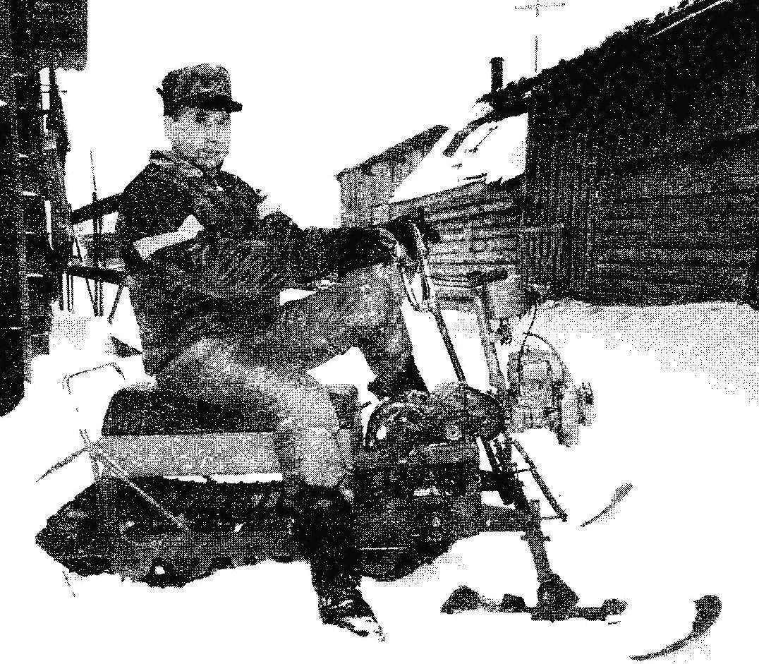
For the manufacture of the second snowmobile was inspired an old petrol-powered saw Ural, which has long been lying idle in the garage due to complete wear of a tire and chain.
However, the engine itself was fine — I repaired before the bookmarks for safekeeping. In health was and reducer. Here both and decided to use the snowmobile. Thoughts ripe and design—or rather, the layout of the power unit, and transmission scheme. Possibly picked up and was getting other parts and components: ski decided to adapt from the snow baby, the caterpillar from the old snowmobile “Buran”.
Based on the size of major components and assemblies, began to design conceived winter car. Although the word “design”is must, in this case too loudly. Rather, it was the process of estimating the mutual arrangement of the mechanisms, since no drawings and sketches are not fulfilled. Are the same as those given in the material, made using a pre-made design to represent the snowmobile readers, as pictures of the General form does not give a complete picture of the car.
The story of the design of the snowmobile will start with the frame. It is based, as, indeed, and crawler unit consists of two welded longitudinal. The middle part of each of them is made from a steel angle 50×36 mm, and front and rear — steel plate 2 mm thick bent at 90° edges (for rigidity). In each of these plates is formed through the grooves of the holes in the front under the drive shaft caterpillars, and in the rear under the axle guides (and also tension) of the gear wheels of the caterpillar. In this tensioning device mounted on both ends of the spars. The cutting device is used to stretch the 2nd stage chain transmission and also ensures the adjustment of track tension in a wider range than if only one rear.
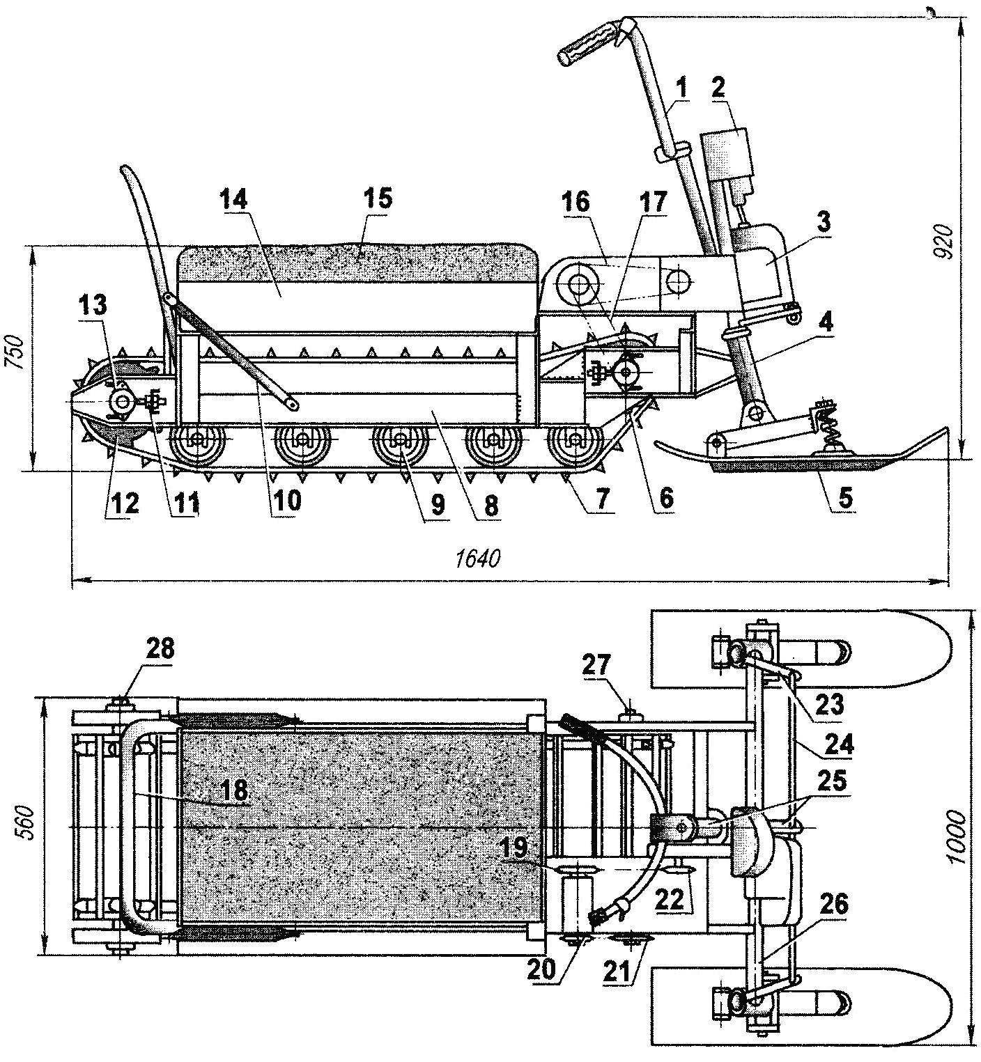
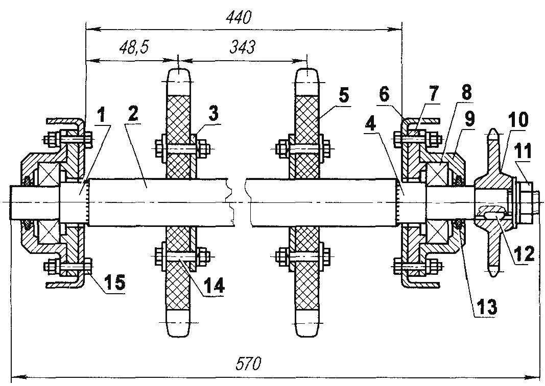
Light motonarty with benzinmotoren from the saw “Ural”:
1 —wheel; 2 — fuel tank (from a chainsaw “Friendship”); 3—power unit (from a chainsaw “Ural”); 4—bushing rack steering skis (pipe Ø30, 2); 5—steering ski (2 pieces): 6—drive gear tracks (nylon, sheet s15. 2); 7—the caterpillar (from a snowmobile “Buran”, cropped); 8—frame; 9—track roller (from potato sorting 18 pieces); 10—brace back-restrictor (pipe 1/2″); 11—tensioner caterpillar (2); 12 — stretch the gear tracks (nylon, sheet s15. 2); 13—the bearing № 80204 in the housing (4 pieces); 14—box-trunk (bottom—plywood, s4 bead—Board s20); 15—seat (cover—s4 plywood, foam, leather); 16 — 1st stage chain transmission; 17 — the 2-nd stage of the chain transmission; 18—back-limiter seat (tube 1/2″); 19—driven sprocket of the 1st chain (a large sprocket of Horomerice—intermediate shaft), z = 38; 20—sprocket 2 stage chain transmission (small asterisk hodomantimer), z = 10; 21 —sprocket driven 2-stage chain transmission (drive sprocket drive shaft caterpillars), z = 18; 22 is the drive sprocket of the 1st stage chain drive (sprocket output shaft of the gearbox), z = 12; 23 —knuckle; 24—tie-rod (2 PCs); 25—steering shaft with a plow; 26—beam front axle (tube Ø30); 27—drive shaft caterpillars; 28 — tension axis of the caterpillar
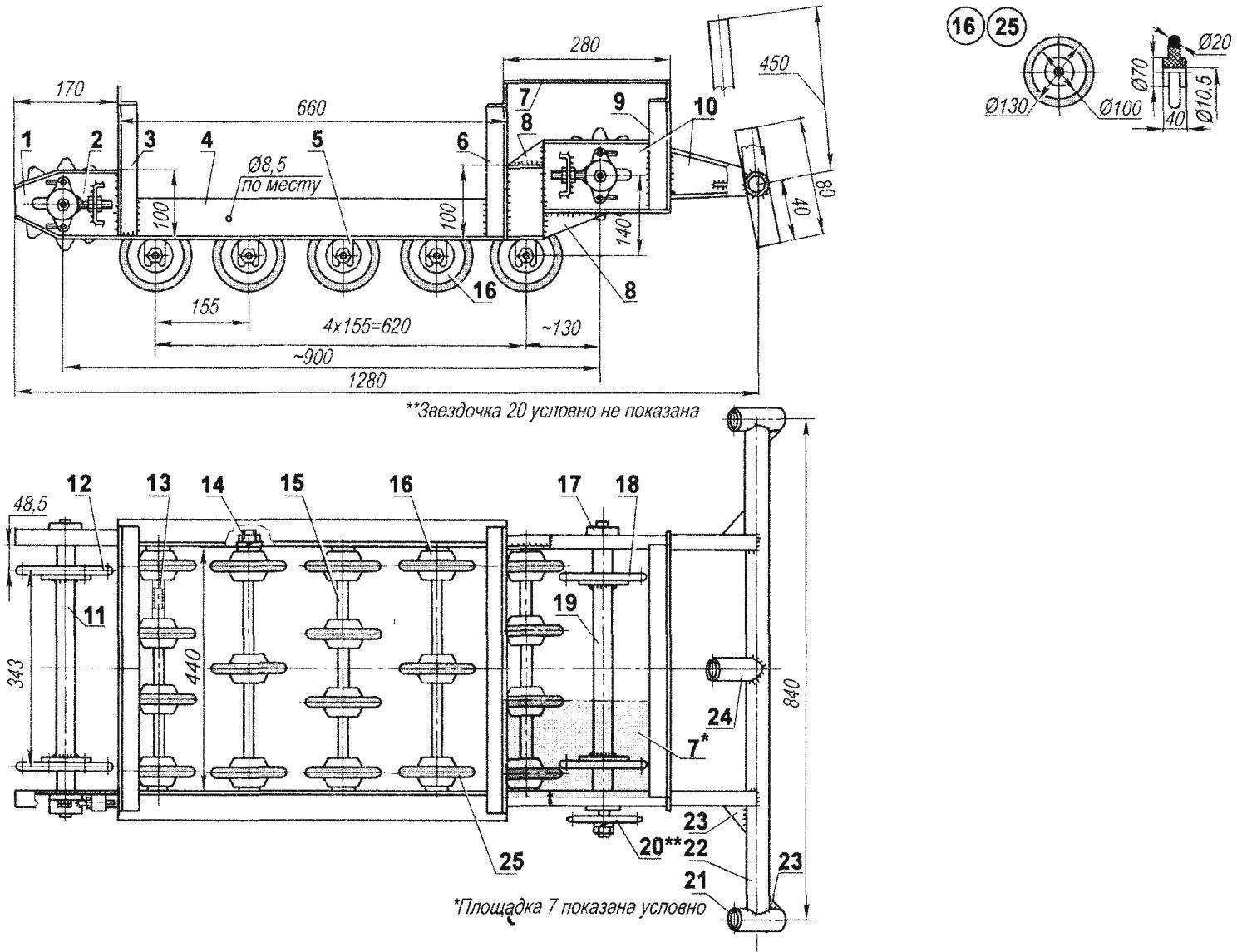
Motoart frame with track unit:
1 — the rear part of the spar (steel sheet s2, flare, 2); 2 — tensioner (4 PCs); 3 — posterior portal (30×30 area); 4—middle part of the spar (the area 50×63, 2 pieces); 5—bracket-plug installation of the axis rollers (steel sheet s2, 10 items); 6 — middle portal (30×30 area): 7—sites for attachment of the gearbox to the power unit and the intermediate shaft-Horomerice (sheet s2); 8 — gusset plate (steel sheet s2,4x); 9— anterior portal (30×30 area); 10—front part of the bulkhead (steel sheet s2 flare); 11 — axis tension gears; 12—stretch gear caterpillar (2); 13—axis of rollers (steel, circle 10, 5 items); 14—fastening axis (M10 nut and spring washer, 20 kompl.); 15—remote sleeve (dural tube); 16 — ice rink (18 PCs.); 17—bearing unit (4 PCs); 18—gauge cog-wheel tracks (2 PCs.); 19—drive shaft caterpillars; 20 — gear shaft sprocket (sprocket driven 2-stage chain transmission), z = 18; 21 —hub steering knuckle steering ski (tube Ø30, 2); 22 — beam front axle (tube Ø30); 23 — gusset plate (4 PCs.); 24 — under engine front (tube Ø30); 25–bandage roller (rubber ring, 18 PCs.)
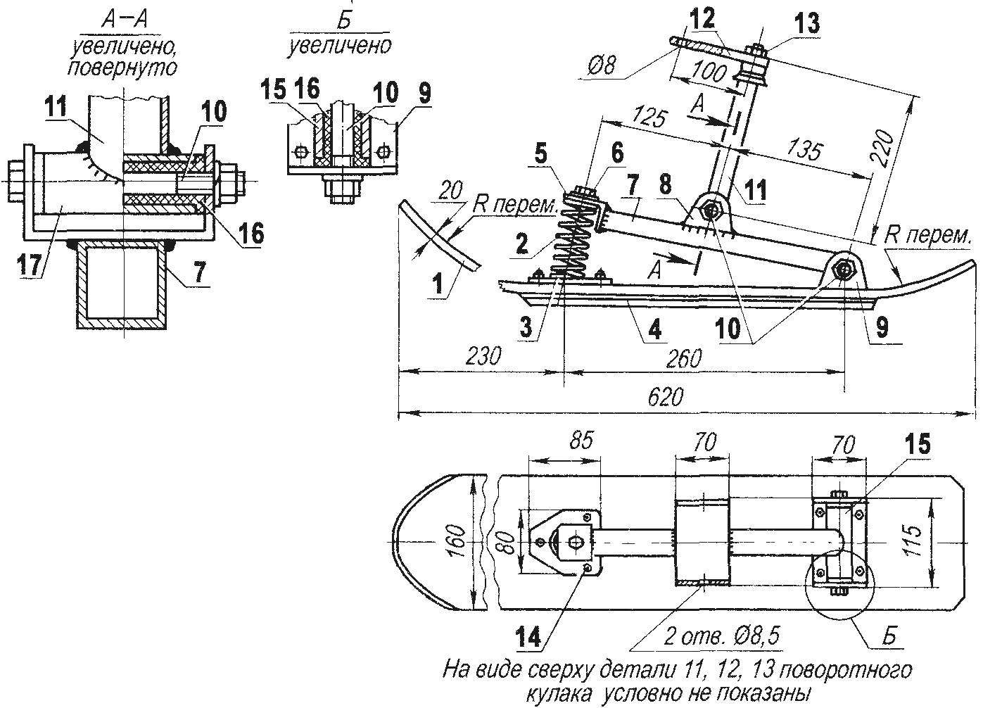
Steering ski:
1 —snake (nylon, sheet s20, from the snow child); 2—spring (normally stretched, the rear shock absorber moped); 3—support bearing of a spring; 4 — the undercut (dural area 20×20); 5 — spring cap (area 35×35); 6— fastening the springs to the cover (bolt M8 with washer); 7 — support arm (pipe 30×30); 8 — lug mounting-plug to lever the ski (steel, sheet s2); 9 — eyelet cradle support arm to the ski (steel, sheet s2); 10 —axis (bolt M8 2 PCs); 11—front steering knuckle (steering bike stand with a crown and a part of the plug); 12—a Pitman arm (steel, sheet s4); 13— mount steering Pitman arm (nut M16); 14 — mount bearing spring and the lugs of the lever to the ski (M5 bolt with countersunk head, 7 pieces); 15 — bushing-lever (steel pipe Ø30); 16 — bearing (nylon bushing, 2 PCs.); 17 — bushing strut (steel tube Ø30)
From the bottom to the side members are welded at equal intervals in the brackets in their open bottom sides of the grooves are inserted the axis of the rollers. Rolls are placed on up to five axes (three or four), and on the edges—each, and in the middle is staggered.
Since we are talking about the supporting rollers, here I note that only 18 pieces and they borrowed from decommissioned potato sorting unit. Rollers are made of nylon and “shod” in rubber tires.
The axis of the rollers is also taken from the agricultural unit of—another— potato digger. The ends of the axles had to let go, in order to be pierced and cut here thread is M10. Between the rollers on the axles wearing spacer sleeves of the dural tube of suitable diameter. The axle brackets are fixed on each side with a nut and lock nut. Add to this that each axis additionally serves as a crossbar, keeping the spars at a certain distance from each other — because of other locking elements in the middle and rear parts of the side members no.
Each side member is welded at the three stands from a steel angle 30×30 mm, United by the same crossbars. Two stands and a crossbar between them to form a small portal. Between the front and middle portal on the right side made of steel 2 mm sheet — it is subsequently mounted reducer chainsaw and the intermediate shaft of the chain transmission. Between the middle and rear portal is a pretty large box, the lid of which serves as a seat, but they will talk about later.
The front ends of the side members are welded to the cross beam (girder) front axle (although a single axle, because the rear is simply no). The beam is made from steel water pipe outer diameter 32 mm with its ends welded to the sleeve tail of the ski, and in the middle front, serving with engine sub-frame. And sleeve, and strut made of the same pipe with the beam. The joints of the sleeves and stand with the beam reinforced with welded gussets made of steel 2 mm sheet.
As has become clear from the above, the propulsion of the snowmobile — tracked. The caterpillar, as mentioned earlier, used from an old “Buran”, but shortened by two feet cut and stitched to the belt.
Gears of tracks like drive and tensioning, made of a nylon sheet with a thickness of 15 mm. are Cut they are in the “image and likeness” gear wheels from a snowmobile “Buran”, one of which was used as a template.
Drive shaft caterpillar tube (outer diameter 28 mm). Him wearing and welded on circular flanges with holes in them and mounted crawler drive gear. At the ends of the shaft, into the outlet pipe are assembled and tack-welded by the welding tips solid-axle, machined for bearings 80204. Thus the right tip is slightly longer than the left. Lengthening performed on the keyway for landing here, driven sprocket 2 stage chain drive (also the drive sprocket shaft caterpillar). Fixed sprocket nut M14—this at the very end of the tip end machined boss that has a corresponding thread.
Tensioning shaft of the caterpillar is exactly the same as the drive, only its both tip the same (as the left drive shaft without the keyway and thread). However, the shaft I call it only for the similarity of power and function is an axis, because this element is not transmitted no torque.
The power unit is a gasoline engine from the saw “Ural” together with its frame mounted on under engine front (it is hinged at the top and the gas tank) welded to the cross beam. Reducer chainsaw is deployed on 180° and is fixed to the platform, which has more “odomenter” (as we in the circle of the local homebrew called intermediate shaft), two-stage chain transmission, from which, indeed, is the whole transmission. Sprocket driven 1st gear (the large intermediate shaft) has 38 teeth and the sprocket 2-tier (small intermediate shaft)-10 teeth. Circuit both stages are the same—are the same as those of motorcycles “Minsk” or “Sunrise” — with a step 15,875 mm.
Steering consists of a supporting steering skis, the levers are connected by rigid rods to fry the steering shaft, that is on the car. The wheel—motor type, double arms. It near the right arm and mounted the control lever gas lever. The brakes on a snowmobile is not—it stops quickly by itself—due to friction in the drivetrain and chassis.
The power of a small motor (5 HP), nevertheless, the snowmobile can reach speeds up to 30 km/h-trodden snow, and even towing a skier or a sled with a weight of 70-80 kg.
Drive shaft caterpillars (idler shaft is the same, only POS.4 is replaced by POS.1):
1—left (in the direction) tip (steel, lap 22); 2 — shaft (steel, pipe Ø28×2); 3 — flange of fastening of a cogwheel to the shaft (steel sheet s4, 2); 4—right (in the direction) of the shaft tip (steel, lap 29); 5—drive gear caterpillar (2); 6—longeron (2); 7 — cover housing bearing (steel, 2pcs); 8—bearing 80204 (2 PCs.); 9 — the bearing housing (steel, 2pcs); 10 — drive sprocket shaft; 11 —fastening the sprockets on the shaft (with extended M12 nut and lock washers; 12—dowel (steel 20); 13—seal (felt, 2); 14—fastening gears to a shaft flange (bolt M8 with extended and spring washer, 8 sets.); 15—mount the bearing housing to the bulkhead (bolt M6 spring washer 4 set).
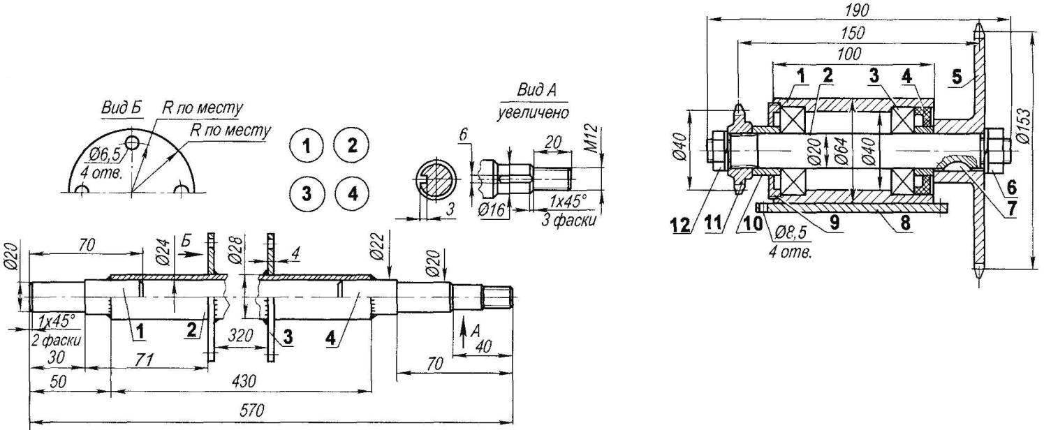
Intermediate shaft bearing support:
1 — bearing housing; 2 — shaft; 3 —the bearing 80204 (2); 4—gland; 5 — the big sprocket z = 38; 6 — nut M20 mounts a large sprocket with a spring washer; 7 — segment dowel; 8 — base; 9—screw cover on the M60; 10 — spacer sleeve (2 PCs); 11 —small sprocket z = 10; 12—nut M14 mounts a small sprocket with a spring washer
The mass of the snowmobile a little more than 40 kg—so its better to call motonarty — that would be more accurate. Fuel consumption not exceeding 1 litre per 6 km, although usually it is enough for 8 km and a Lot of cargo fits in a drawer under the seat; there are usually 5-liter canister with a supply of gasoline (volume of standard tank—2 liters), tool kit, axe and other equipment.
When traveling into the forest for firewood or timber in the trunk of the saw taking the bus and gearbox—benzinmotor removed from the sled and installed on the saw.
The walls of the box under the seat is made from boards-twenties, and the bottom is from four-layer plywood. The lid serves as a seat. It is made from 6 mm plywood, overlaid with several layers of foam, covered with leatherette. To the walls of the box cover is mounted on two card loop (locked) window latches. Seat leans back and the rear arc serves as a limiter.
Unpretentious and the engine starts fairly easily even in 30-degree cold, but because the car was really winter. Although to drive it in this cold is risky; it is easy and bitten—because motonarty-open.
A. STARTSEV, p/o Monastyrskaya Pashnya, Arkhangelsk region.
Recommend to read
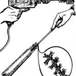 USLUZHLIVYE BRUSH
To clean the inside of the tube or a long narrow cavity is not so simple. This can help "brush" like how to wash their bottles, only to make it necessary from segments of a steel cable....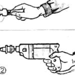 FIRST, GLASS CUTTER
To drill from the opening in the wall, lined with tiles, for example in the bathroom, I first clean lazurevy layer rotational motion of an ordinary glass cutter, carbide wheel pressed in...
