“I intend to build a car for widespread use. It will be large enough to fit an entire family, but small enough for one person to operate it. It will be made of the best material and constructed using the simplest methods possible in modern technology. Despite this, its price will be so low that anyone who receives a decent allowance will be able to buy themselves a car in order to enjoy a vacation with their family in the free, clean air.”
These words do not belong to me, but to one of the most famous automobile manufacturers – Henry Ford. They were written about 70 years ago, but the basic principles of design – no matter industrial or amateur – remain the same today.
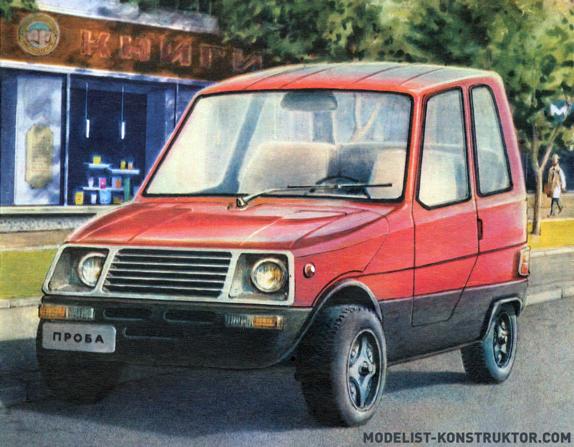
Extreme simplicity, minimal weight, minimal dimensions with optimal convenience; the most affordable materials, components and assemblies; the most simplified (without compromising quality) manufacturing technology – all this became the basis for the design of my car, which later received the name “Yauza-035”.
It became possible to construct a light and rigid body from a cheap and durable material – hardboard; frame – made of readily available steel pipes; power plant – based on a two-cylinder motorcycle engine IZH-Yu4 with a displacement of 350 cm3 (hence the index 035 in the name of the car) with a power of 27 hp. With. However, it is probably worth introducing readers in more detail to the design features of this miniature city car.
The FRAME of the minicar is flat, tubular, welded. Its basis is a power “triangle” welded from Ø42X3 mm pipes, on which the suspension rockers of the front and rear wheels are mounted. The joints of the frame elements are reinforced with steel gussets 3 mm thick.
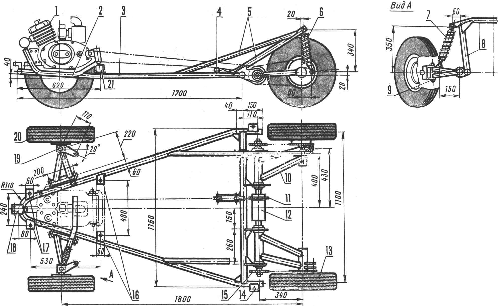
1 – engine of the Izh-Yu4 type with a power of 27 hp. pp., 2 – sub-engine frame (cut from the old frame of the Izh motorcycle), 3 – frame (steel pipe Ø 42X3 mm), 4 – tension sprocket, 5 – rear shock absorber support (pipe with a diameter of 42X3 mm and 30X2 mm), 6 – rear shock absorber (from the Izh motorcycle), 7 – front shock absorber (from the Izh motorcycle), 8 – front shock absorber support (pipes with a diameter of 36X3 mm), 9 – front suspension rocker, 10 – rear suspension rocker, 11 – central intermediate sprocket of the chain drive. 12 — double overrunning clutch, 13 — rear wheel (from the S3D motorized stroller), 14 — rear docking support of the body, 15 — side intermediate sprocket of the chain drive, 16 — rear supports of the sub-engine frame (steel strip 5 mm thick), 17 — front supports of the sub-engine frame frame (steel strip 5 mm thick), 18 — front connecting support of the body and frame (steel strip 5 mm thick), 19 — steering knuckle (steel channel No. 12 and steel strip 5 mm thick), 20 — front wheel (from the S3D motorized stroller ), 21 — rubber cushion.
The REAR AXLE of the machine is designed according to a differential-free design using roller overrunning clutches interlocked into a single unit. It should be noted that the installation of the rear axle requires special precision; It is necessary to ensure that the axes of the rocking chairs are strictly on the same line. To do this, pre-prepared brackets are placed on a flat steel rod or pipe and in this form are secured to the transverse element of the frame with 3-4 welding points each. If after tacking no significant distortions are observed (that is, the technological rod can be removed quite freely from the holes in the brackets), the joints are finally welded. If welding causes the knot to become loose, it can only be corrected by straightening.
Each of the longitudinally swinging arms of the rear suspension is welded from tubular blanks, as shown in the pictures. First, grooves are made in the central pipe for bearing No. 204 and for the sliding bearing on which the rocker is suspended. The plain bearings themselves are stepped bronze bushings, secured to brackets using M6 bolts and nuts.
The rear wheels are driven by a two-stage chain transmission. Two intermediate sprockets are mounted on intermediate shafts (fixed with keys), which rotate inside the central pipes of the rocker on bearings No. 204. The third intermediate sprocket is welded to the overrunning clutch housing.
The double overrunning clutch is a tubular body; On each of the end sides, stepped bushings are pressed into it, machined from a material with high surface hardness (for example, 45 steel – hardened), and fixed in the pipe using so-called “electric rivets”. This method of fixation consists of cutting two or three holes Ø8…10 mm in the pipe and welding them using electric welding. Welding should be carried out promptly to avoid tempering of the hardened bushing.
The mating parts of the overrunning clutch are also made of material with high surface hardness. They are fixed to the intermediate shafts using electric welding. As rollers, pieces of silver wire (material – 50HFA) Ø6 mm (hardened) are used. Of course, it is better to select rollers of the appropriate diameter from the bearing, but during the manufacture of the overrunning clutch I did not have such parts on hand. However, homemade videos also performed well.
1 – diagonal cross member (steel pipe Ø34X3 mm), 2 – cross member (steel pipe Ø34X3 mm), 3 – steering knuckle sliding bearing (bronze bushing), 4 – steering knuckle bearing housing (steel pipe Ø40X3 mm), 5 – M14 bolt with nut and washer; (the connection is fixed with a cotter pin), 6 — shock absorber mounting ear, 7 — suspension arm bracket (steel strip 5 mm thick), 8 — side of the car frame (steel pipe Ø42X 3 mm), 9 — bearing housing of the rocker arm, 10 — plain bearing lever (bronze bushing).
Each of the rollers is pressed by a spring – if you can’t find a ready-made one (with an outer diameter of 5.5 mm from Ø0.5 mm wire), you can wind it yourself on a suitable rod using a simple device consisting of two planks, between which it is clamped in a vice this rod.
It should be noted that the operation of the overrunning clutch significantly depends on the care taken in its manufacture. Its main element – the body with rollers and springs – must be absolutely symmetrical. It is advisable to mill it using a dividing head, turning the workpiece strictly 90° each time. An indispensable condition for satisfactory operation of the coupling is, as already mentioned, strict alignment of the intermediate shafts. A well-made and assembled overrunning clutch ensures almost instantaneous engagement of the driven shaft at the start of movement and equally instantaneous separation of the housing and the axle shaft during advanced rotation of the latter. I also note that there are many designs of overrunning clutches, and the choice of any of them is a matter of the technological capabilities of the amateur designer. According to reviews from home-made workers, good results are obtained by using a “ratchet” designed like a similar device for sports and light-road bicycles.
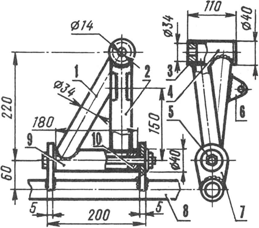
The FRONT AXLE of the microcar is also homemade; it is a device with independent suspension on oblique arms and shock absorbers of the rear wheel of an IZH motorcycle. Each of the levers is assembled by welding from pipes Ø34 mm and Ø40 mm. It is best to weld workpieces on a simple bench, on which the bearing housings of the rocker arm and steering knuckle should be clearly fixed. Please note that the latter is installed so as to ensure a camber of 3…4° (with a horizontal position of the suspension arm axis) and an inclination of the steering knuckle pin axis of 5°. In this case, the front wheels are not perpendicular to the plane of the road, but inclined at an angle of 3…40 to the vertical. This reduces the torque required to rotate the axle around the king pin. The tilt of the steering knuckle pin provides a significant increase in stability when driving: after the influence on the steering wheel ceases, the latter “on its own” returns to its original (neutral) position.
The housings of the swing arm and knuckle are equipped with plain bearings – stepped bronze bushings.
The steering knuckles are pieces of steel channel No. 12 (its height is 120 mm, width is 52 mm, the thickness of the vertical wall is 4.8 mm, the average thickness of the horizontal flange is 7.8 mm), to which the turned axles of the front wheels are welded. To do this, a hole Ø30 mm is cut in the steering knuckle, and the axle is made in the form of a stepped roller with a seat diameter of 30 mm. The trunnion and knuckle are welded using two circumferential seams on both sides of the channel. The steering linkage steering arms are cut from 5 mm thick steel sheet and welded to the lower areas of the steering knuckles.
ENGINE of a miniature passenger car – type IZH-U4. This is a two-cylinder two-stroke engine with a power of about 27 hp. s., equipped, like all two-stroke motorcycle power units, with a clutch, a four-speed gearbox (unfortunately, without reverse gear) and an alternator. In addition, to operate the engine, a rectifier-regulator unit and a 12-volt motorcycle battery are required.
The engine is installed on a special subframe, consisting of part of the frame of the old Jupiter, welded to two steel channels about 70 mm high. The engine is attached to the subframe using standard fasteners, and the subframe itself is attached to the car frame through rubber pads, as shown in the pictures. To attach the subframe to the frame, support platforms are provided, cut from a steel sheet 4 mm thick and welded to the frame pipes.
The DRIVE of the driving wheels, as already mentioned, is a two-stage chain transmission, and the intermediate sprockets are located on the intermediate shafts and on the body of the overrunning double clutch. This design of the rear axle ensures its independent suspension without the use of labor-intensive and low-tech differentials with cardan drives in a home workshop (with a record low coupling weight).
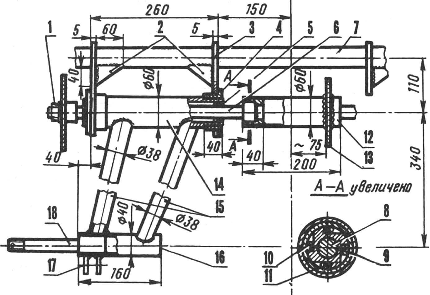
1 — sprocket mounting nut (fixed with a cotter pin), 2 — gussets (steel strip 3 mm thick), 3 — suspension arm bracket (steel sheet 5 mm thick), 4 — lever sliding bearing (bronze bushing), 5 — ball bearing No. 204 , 6 – spacer bushings (steel pipe with an internal diameter of 20 mm), 7 – frame cross member (steel pipe Ø42X3 mm), 8 – intermediate shaft of the chain drive, 9 – overrunning clutch bushing (fixed in the body with electric rivets), 10 – roller and spring clutch, 11 — driven part of the overrunning clutch, 12 — overrunning clutch housing (pipe Ø60 mm), 13 — overrunning clutch sprocket (welded to the body), 14 — bearing housing of the rocker lever (steel pipe Ø60 mm), 15 — longitudinal elements of the lever (steel pipes Ø38X3 mm), 16 — axle shaft housing (steel pipe Ø40X3 mm), 17 — rear shock absorber mounting fork (steel strip 4 mm thick), 18 — axle shaft (fixed with electric rivets).
The chain drive sprockets are homemade, they are cut from steel sheet blanks 5 mm thick. They were manufactured using well-known technology using a drilling machine, hacksaw and files. A hole was cut in the central intermediate sprocket along the diameter of the overrunning clutch housing, after which the sprocket was welded to it. The other two side sprockets were fixed by welding to a steel bushing with an internal keyway. A corresponding groove was milled on the intermediate shafts. The rear wheel sprockets are from the Izh motorcycle.
STEERING – from the S3D motorized stroller. The transverse rod is split, using a steering lever – a “triangle” similar to the “Duet” car of the Vologda designer A. Krylov (by the way, much in the “Yauza” was borrowed from the developments of this designer – the minicar “Verblyuzhonok” (“M-K” No. 6 for 1987) and “Duet” (“M-K” No. 8 for 1990).
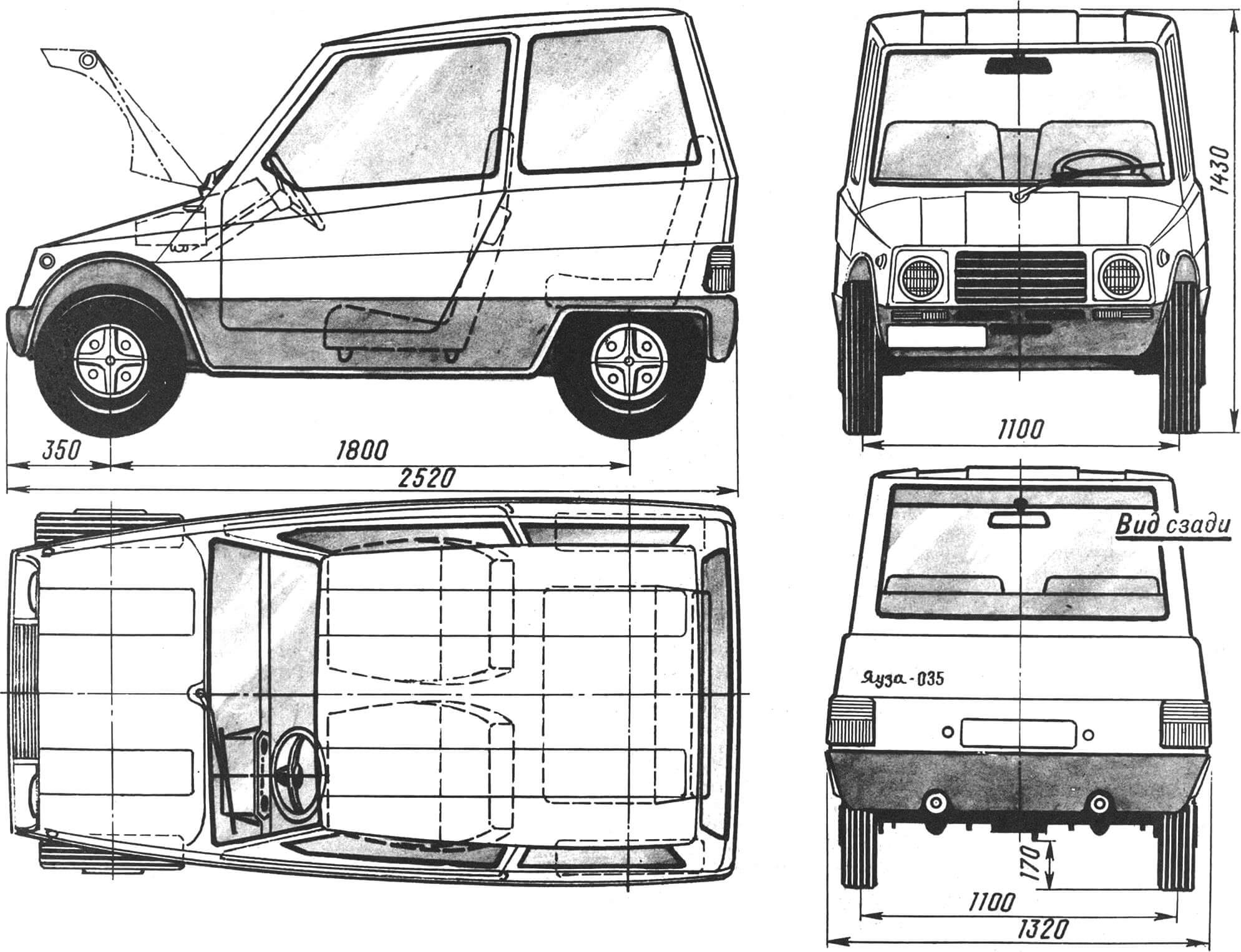
The BODY of the Yauza-035 car is with a wooden frame and hardboard casing. Work on manufacturing the body begins with drawing a plaza on a sheet of plywood on a scale of 1:1. Next, blanks for frames and stringers are cut along the plaza. It should be noted that the central frame is glued together from five wooden blocks and reinforced from the inside with plywood gussets.
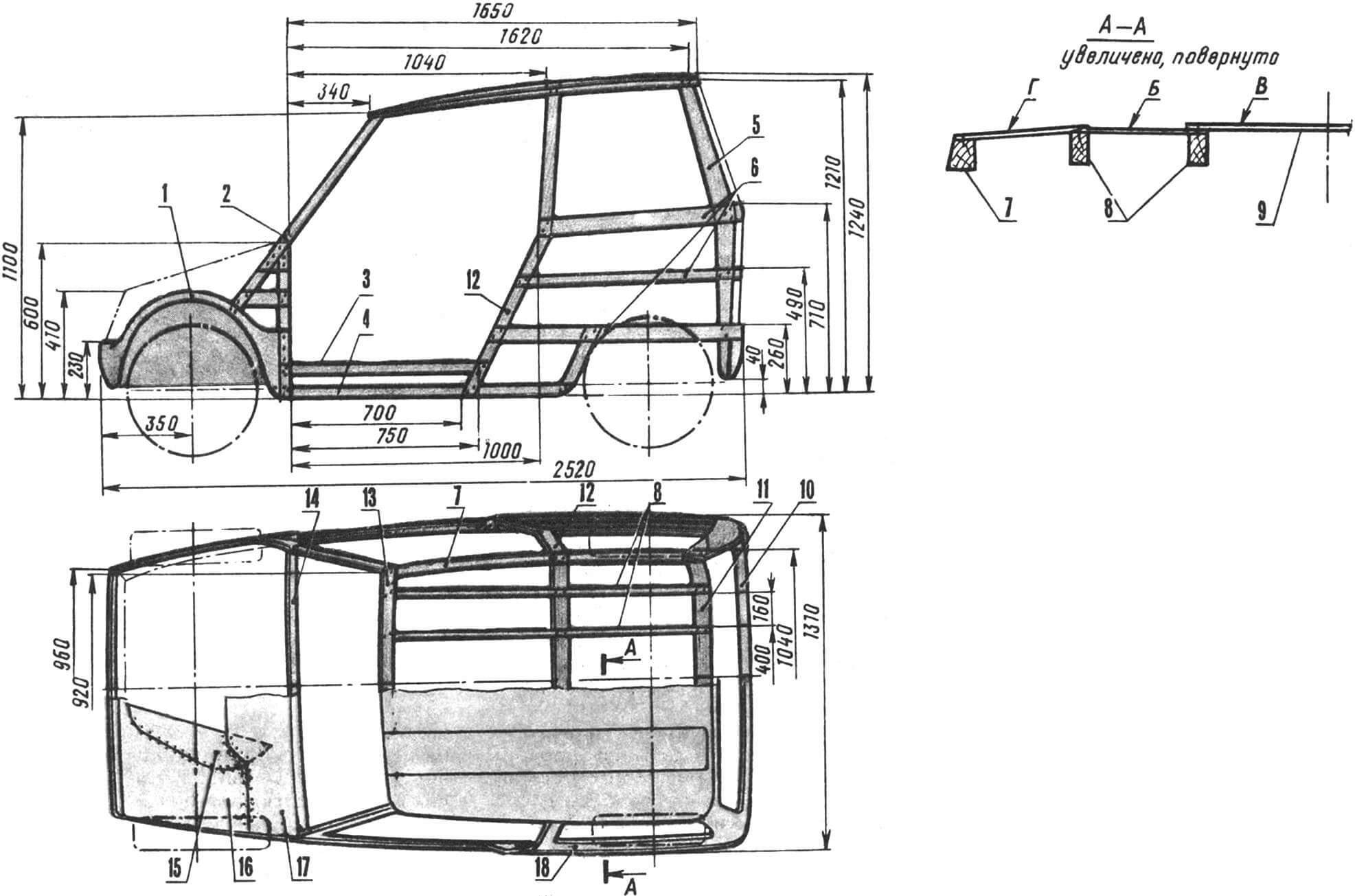
1 – elements of the wheel niche frame (plywood 20 mm thick), 2, 13 and 14 – elements of the front frame (wooden slats 25 mm thick), 3 – sill (rail with a section of 25X40 mm), 4 – block of the body base (section – 40X40 mm), 5, 11 – elements of the rear frame (wooden slats 25 mm thick), 6 – longitudinal frame of the body (wooden slats 26 mm thick), 7 – longitudinal side elements of the roof (slats 25X40 mm), 8 – roof stringers (slats thick 25 mm), 9 — roof lining (hardboard strips 4…5 mm thick), 10 — cross members of the rear part of the body (3 pieces, slats 25 mm thick), 12 — central frame (glued from 30X40 mm slats and plywood), 15 , 16 and 17 – trim of the wheel niche and engine compartment (plywood 6…8 mm thick), 18 – trim of the sidewalls and rear of the body (hardboard 4…5 mm thick).
The door frame is also wooden. The glazing of the door, as well as the rear side and rear windows is made of plexiglass. The glass in the doors is rigidly fixed and cannot be lowered, but there is a round window cut into the glass itself, covered with a lid made of the same plexiglass.
The surface of the body is formed by ruled (single curvature) surfaces, however, thanks to its rather impressive shape, the body of the Yauza-035 does not give the impression of being simplified or primitive. The fact is that the skin of the roof, sides and hood consists of several sheets of hardboard, connected to the frame so that the impression of a single surface is created with stampings to increase rigidity. Each of the cladding elements is a ruled surface, and the entire cladding has the appearance of a double curvature shell.
How this is done is easy to understand using the example of roof molding. To begin with, two strips of hardboard are cut out and they are used to seal zone B, as shown in the figure. Next, a blank is cut out for covering zone D and carefully adjusted to the frame. Pay special attention to the adjustment of the joints of the hardboard strips. The sheathing is secured with small screws and epoxy glue. The hardboard strip is also adjusted to the central zone of the roof (zone B). After installing the sheathing strips in the places where they join, a rounding is made using epoxy putty – a fillet.
The sides of the body and the hood are trimmed in the same way. I note that before sheathing the sidewalls, the doors are temporarily secured in the openings using clamps or screws and sheathed integrally with the sidewalls. After the resin has cured, the trim between the door frame and the door “frame” is cut from the inside with a fine-toothed hacksaw. Together with the body, the alligator-type hinged hood frame is sheathed with hardboard and then cut off from the body in the same way as the doors.
Covered with hardboard, the body is puttied, sanded and covered in one layer of fiberglass with epoxy resin. Then its surface is sanded, primed and painted with synthetic (for example, alkyd) enamels in three or four transitions with intermediate puttying and sanding.
The inside of the body is covered with strips of packaging or construction foam, which significantly reduces the noise level in the cabin. Then the foam is leveled to the height of the stringers and covered with artificial leather. The inner surface of the doors is also filled with foam plastic, after which it is sewn up with laminated plastic and covered with artificial leather.
As an instrument panel, it is best to use the Izh-U4 motorcycle unit, which contains the ignition switch, speedometer, as well as control lamps for the “neutral” of the gearbox, turn signal, ignition switch and high beam. This unit can be easily installed in a convenient area for the driver on the panel.
The driver’s and passenger’s seats and the rear (children’s) sofa are homemade. All of them are lightweight tubular frames (made of duralumin pipes Ø22 mm), covered with nylon cord. Foam rubber was glued over the cord, after which the chairs were covered with furniture fabric.
A few words about the car controls. As you know, a motorcycle engine (including the Izh-Yu4) is equipped with a foot kick starter, a foot switch for the gearbox, and also has cable drives for the carburetor throttle, fuel corrector and clutch mechanism. All this had to be converted into a typical car combination of pedals and levers.
The clutch drive remained cable, but it connects to the pedal located under the left foot of the driver. Under the right foot – the pedal of the throttle shift of the carburetor (accelerator) connecting the cable in the Bowden shell with the carburetor. On the right side of the driver’s chair is a gearbox lever that connects with a traction with a cutting regular engine gearbox. A hand-to-hand gear shift lever can only move back and forth. In this case, the first gear is turned on from neutral forward; Consistent movements of the lever back include second, third and fourth gears.
The engine is launched by a kickstarter, however, instead of a standard launch pedal, a steel pulley is fixed on the shaft, around which two turns of a nylon cord are transferred. One of the ends of the cord is fixed on the pulley, and the second is displayed under the dashboard and fixed on a convenient textolite handle. The launch of the motor is carried out by a sharp jerk for it, after which it is fond of the return spring of the starting device under the dashboard.
The floor of the salon is from plywood with a thickness of 12 mm, soaked in hot olifa (by the way, all the wooden and organ parts of the body are subjected to the same processing), and then Movil. A trapezoidal box in the cross section is built between the chairs of the driver and the passenger, inside which the drive chain passes.
And one last thing. Cooling of the micro -automotive engine occurs in the same way as on a motorcycle – with a oncoming stream of air, especially since hot cylinders are located directly behind the air intake. Indeed, in the process of movement there is no overheating of the motor, but in the absence of blowing (for example, on long -term parking at traffic lights, in jams, with a strong high wind), its temperature increases rapidly, the danger of jamming the pistons in the cylinders appears. To prevent this from happening, an electric fan is located in the engine compartment – a duralumin impeller, mounted on the engine axis from the glass cleaner of the motor -coolae. Its power is enough to ensure cooling in critical situations.
Technical characteristics of the car “Yauza-035”
Overall dimensions, mm)
length 2520
Width 1320
Height 1430
Base (mm) 1800
Track (mm) 1100
Clearance (mm) 170
Mass minor car (kg)
Dry 400
Full 620
The highest acceptable speed (km/h) 80
IZH-Yu4 engine
Engine power (p.) 27
Transmission from the engine is chain, two -stage
The front suspension is independent, on oblique levers with shock absorbers Izh-Yu4.
The rear suspension is independent, on longitudinally swinging levers with shock absorbers “IZH-YU4”.
Fuel tank capacity (L) 18
M. Yaroshevich, engineer, Minsk
Recommend to read
 GUM TO RESTORE ORDER
To the power cord with the phone charger and other appliances compactly laid down in his place, his need to tightly wrap around the body of the plug or charger, and the end with the plug... SCHOOL OF AIRCRAFT (PART 5)
GLIDER OR GLIDER? Unpowered gliding flight has long attracted man. It would seem that what is easier is attached to the back wings, jumped down the mountain and ... flew. Alas, many...
