 When employees of Institute of petrochemical and gas industry named. Gubkin turned in a circle electronic automation of the Moscow Palace of pioneers with a request to produce thermostats for chemical experiments, it is to no one’s surprise. Is not the first creative activities of the children’s team, led by F. Y. Yerokhin, goes jobs scientific institutions and industrial enterprises of Moscow. So this time they decided posed a technical challenge.
In the development and manufacturing of the prototype took an active part Vyacheslav Nogin was a pupil of the Moscow school № 71. Here is what he said about the design of the device.
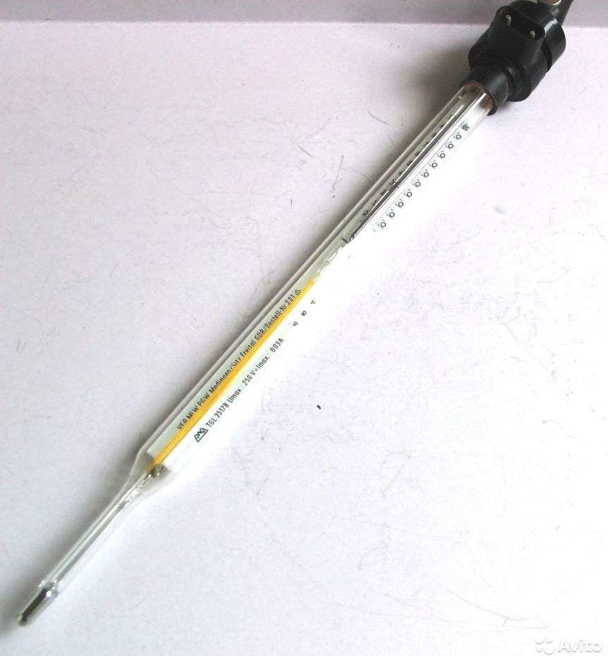
The thermostat’s signal contact with a mercury thermometer needs to turn on and off the heater. It was a condition to using the contact thermometer was leaking a small current fraction of a microampere. Otherwise, it may occur electric discharge, and the thermometer goes down.
Scheme of a simple thermostat (Fig. 1). It contains two transistors, diode, relay, resistor four; powered by a DC source voltage of 12 V.
The current through the contacts of the thermometer is 0.2 µa. The device is included in the open circuit bias of transistor T1. Moreover, the resistor R2 is connected to its base, otherwise the current flowing through T1, may be sufficient for opening the transistor T2.
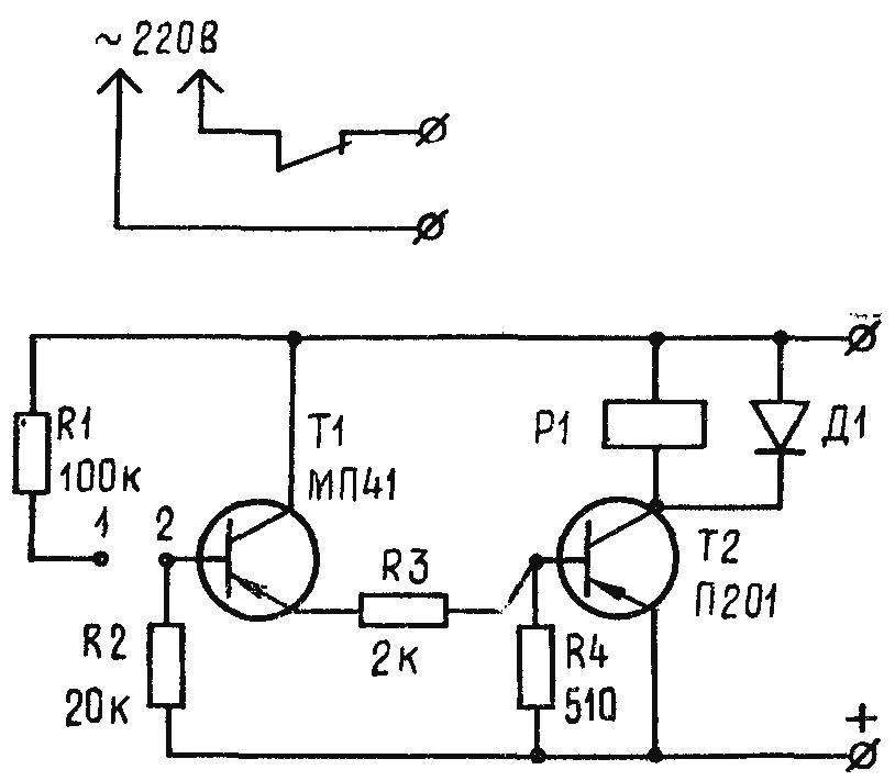
Fig. 1. Schematic diagram of the temperature controller.
In the initial state when the contacts of the thermometer are not closed, both transistors are locked and the relay includes a heater. When the temperature reaches a certain value, the contacts of the thermometer short circuit 1-2 and the transistor T1 opens. This, in turn, causes opening and the transistor T2 in the collector circuit of which relay R1. Its contacts disconnect the heater. When the thermometer’s contacts open, the circuit returns to its original state, and the heater turns on again.
Resistor R3 prevents T2 from the big base currents, and the resistor R4 speeds up the output of the same transistor from saturation mode when turned off. Diode D1, connected in parallel to the relay coil R1, dampens EMF of self-induction, preventing T2 from the breakdown.
Going device on the PCB with size 110X70 mm foil fiberglass or Micarta (Fig. 2).
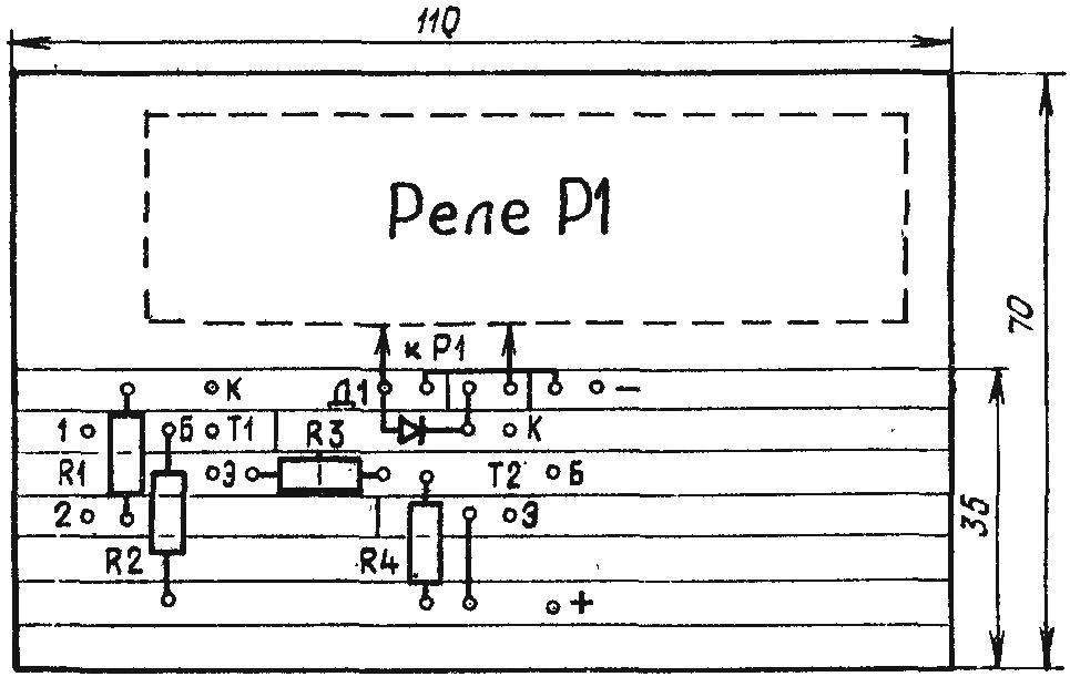
Fig. 2. Printed circuit Board with the location details.
Parts used in the controller available. Transistors: T1 МП13 — МП16, МП39 — МП42 with any letter designation, T2 П201 — П203, П213 — П217. Resistors — sun or MLT. RCN relay R1 must operate from 12 V at a current of 40 mA (passport RF4.530.810). Diode D7, D226, Д202 — Д205.
The device is housed in a plywood or plastic case size 120X90X80 mm. On the top cover installed terminals to connect the heater and thermometer.
To establish the thermostat is easy. Connect the 12V power supply and short out the circuit at the points 1, 2. If the relay does not work, connect the emitter and collector of T1. Relay on indicates a fault or a small gain of T1. Otherwise, the faulty transistor T2, or it has a low gain.
Recommend to read
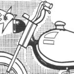 WARNING LIGHT-IMPROMPTU
If your old moped or motorcycle there is a warning light that tells the driver about turning on lights, it is not necessary to open the harness wiring and to connect additional warning... WHERE TO PUT THE WRECKAGE OF THE SAWS?
And really, where? To throw away? It is a pity, after all, made of fine steel, they may be able to provide for drilling in the sheet material of large diameter holes. The holder design...
