
 On the instructions of the enterprises of Dzerzhinsk-khimpromenergo in the design office of the school # 2 of Dzerzhinsk, Gorky region, the guys have designed and built a device for measuring the pressure of neutral media in the pipes — an electronic pressure gauge. One of its founders, a student of the tenth class Sergey Whalin, said that the installation or repair of compressors necessary to carry out Express-analysis of the condition of the equipment. Devices, testifying to the extent necessary for a specific production, yet.
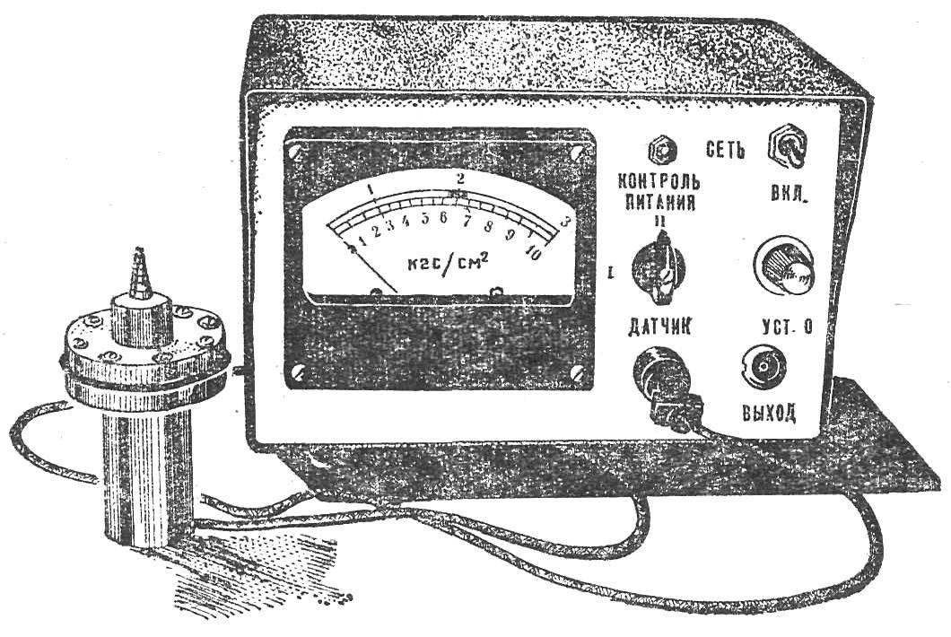
The company made technical specifications for the manufacture of non-standard electronic gauge with interchangeable probes. The device should be portable, powered by an Autonomous power source (battery, battery). The measurement accuracy in the range of 3-10 kgf/cm2 — up to 1.5%. Measurement range from 0.1 to 10 kgf/cm2.
During the past academic year, the device was designed, manufactured and delivered for testing to the customer.
Now how does this electronic gauge. The generator on the transistor V2 is assembled according to the scheme of inductive treatacne. Stability of the oscillations of the oscillator amplitude and frequency is provided by a high q resonant circuit L1, C1 and the introduction temperature stabilization. This base V2 is enabled through the divider, and the transistor is selected with a small reverse collector current.
Through the capacitor C3, the oscillation frequency of 2 MHz received at the resonant amplifier of high frequency (V3). The amplitude of the voltage from coil L3 of the connection depends on the configuration of the resonant circuit L2, C4.
From the amplifier-detector V4 DC voltage is supplied to the measuring bridge, assembled on the transistor V5. With the help of variable resistor R18 produces zero. Switch S1 has three positions: two first — change the measuring range, the third control voltage.
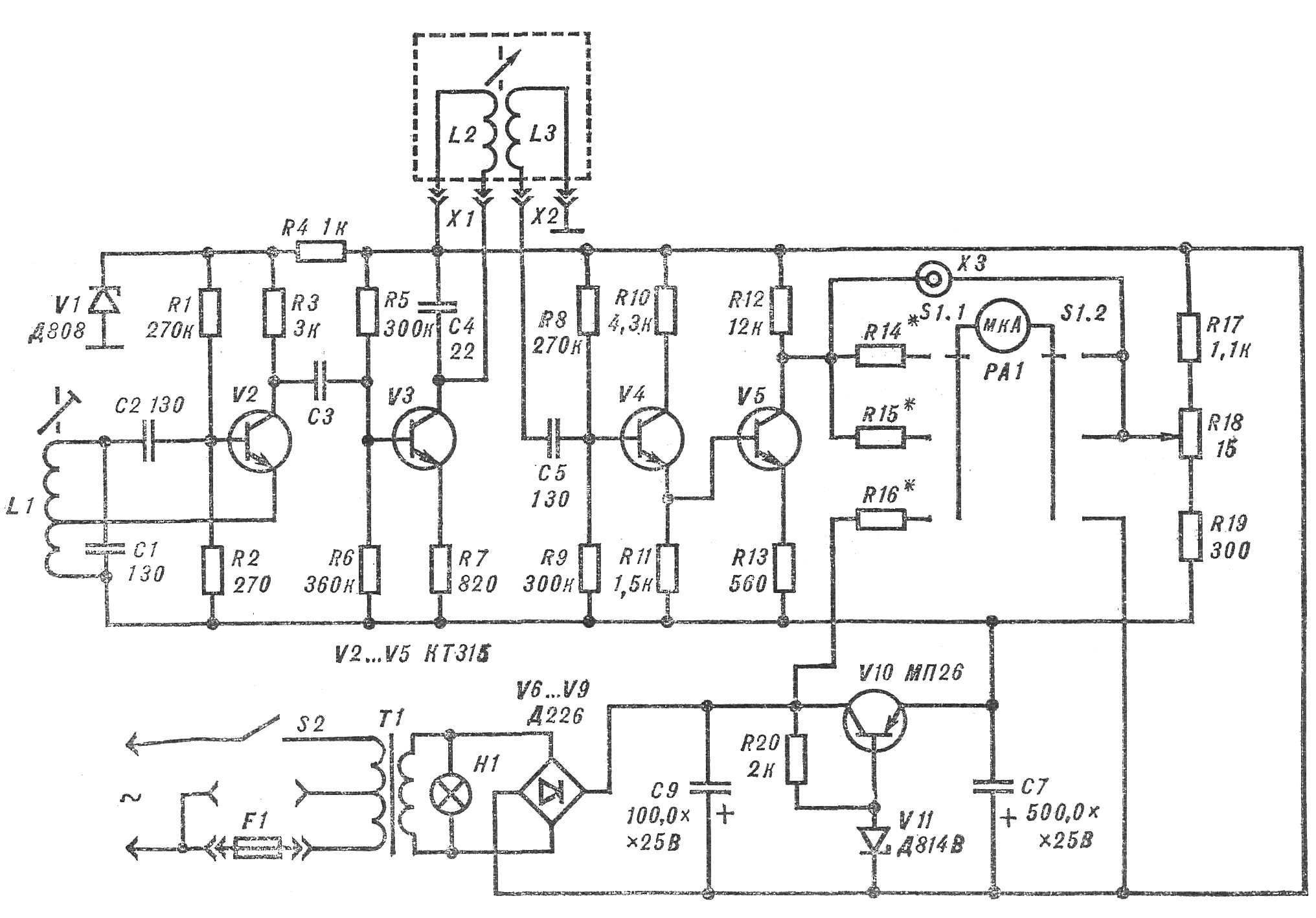
Schematic diagram of the device for measuring pressure.
When the pressure on the diaphragm increases, the natural frequency of the circuit L2, C4 begins to approach the frequency of the oscillations produced by the generator. The amplitude of the AC voltage from the coil when L3 increases, and the needle of a milliammeter is rejected.
The measuring bridge is set to zero when the oscillation frequency of the circuit close to 1.8 MHz. Since the resonance curve has no straight sections, and the scale of the instrument is nonlinear. At the bottom position of the core frequency oscillation of the circuit L2, C4 does not reach the inflection point of the resonance curve, so the nature of the nonlinearity of the scale is not changed. In this device the optimal frequency is in the range of 1.8— 1.9 MHz (the frequency of the oscillator 2 MHz).
A stabilized power supply. Consumed from the mains power — no more than 5 watts from batteries — 1 watt.
The transducer of the diaphragm type. The membrane is made from Dacron impregnated with rubber, and is connected with a spring-loaded rod, at the opposite end of which is mounted a ferrite rod — core coils L2, L3.
All the details of the sensor are made of non-magnetic materials.
Recommend to read
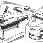 HYDRAULIC PIPE BENDER
The main element of such a tool is a hydraulic Jack used for lift trucks. The lift is rigidly fixed on a steel baseplate to fit. On the rod of the Jack is put on a mandrel of aluminum...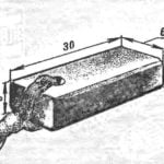 NO WORSE THAN FACTORY
Brush motor run relatively short. And if not in stock new, home "helper" comes the forced inaction. Meanwhile, a new brush it is easy to make from coal cores extracted from the...
