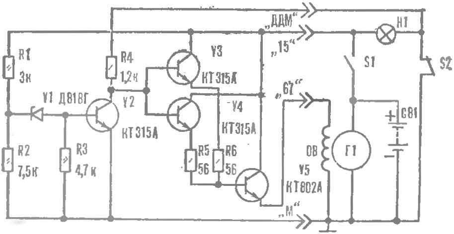
In the case of ERN on the signals of the rotation causes large changes in the excitation current of the generator than at normal voltage regulator. This indicates that ERN has time to follow all the changes of the load of the vehicle electrical system, did not cause a significant overvoltage on the field winding having a large inductance. The reason is that at the moment of locking of the transistor V5, the EMF of a winding applied to its emitter in a polarity otricatelniy, not allowing a sharp lock V5. Thus does not occur over-voltage of the collector and the reliability of the output transistor increases.
Of the resistors R1 and R2 are selected from a calculation that ERN was supported by the battery voltage (in the on-Board mains of the vehicle) is 13.5—13.8 V regardless of load changes. At this voltage the battery will not charge above the allowable standards, not “boiling” the electrolyte. To raise the voltage of the generator is sufficient to reduce the resistance of the resistor R2 or R4 to 1 Ohm.
Check serviceability ERNE, measuring the voltage at terminals “15” and “67”. With the ignition on and the engine off, the voltage at the first the same as that of the battery, and the second it is equal to 0 V. When the engine is running, voltage at terminal “15” at any speed should be at 13.8 to 14.2 V (depending on the settings of ERN).
Circuit Board of ERN with a scheme of arrangement of parts.
Electronic voltage regulator as part of the V5 is permissible to use the transistors КТ803, KT805, КТ817. and instead of two semiconductor triodes V3 and V4 can be set to one n-p-n conduction with a collector current of at least 150mA and the voltage’ on it above 15 In (eg. series КТ503, КТ815). The transistor V2 (КТ315А) can be replaced by КТ312Б, V. Zener Д818Г replaces a similar device brand Д814Б, Д818Д or Д818Е.
Elements of the ERN placed on the Board, made of one-sided foil fiberglass method of cutting the foil on the conductive areas. Contact petals of the connector is made of sheet brass. Through the holes in them cost attached to getincome bracket (base ERN). The other two holes are used to install the radiator of the transistor V5, the Radiator is ribbed, size 35 40×45 mm. to the Top screwed plastic case from a standard voltage regulator with vent holes in the upper and lower parts of the side walls. You can use any other container with similar dimensions.
When you exit failure warning lamp or oil pressure sensor transistors V3—V5 are locked and the lamp control of the generator. The same result is obtained by reducing davlenia oil below norm. This reduces the possibility of engine run with a faulty lubrication system.
 Many motorists available means, to improve the performance of various components of your machine. Considerable help in providing them electronics. To take at least a variety of electronic ignition system, which “M-K” repeatedly told. Today we offer the owners of “Lada” and “Cossacks” to build a simple electronic voltage regulator (ZRN), constructed in Kharkiv by B. Krutikova.
