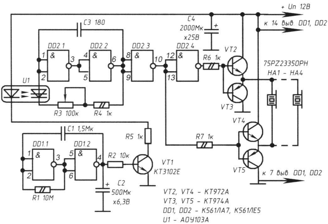
On the elements DD1.1 and DD1.2 collected waveform generator subsonic frequencies (INCH), “loaded” on the transistor VT1. This transistor acts as a current amplifier and at the same time an electronic key to control the optocoupler U1. As applied optocoupler thyristor optocoupler, performing the role of a managed key.
The shape of the pulses at the output of this generator is rectangular, so the transistor VT1, depending on the edge of the pulse periodically opens and closes slowly (with a frequency generator INCH). Optocoupler U1, included in the collector circuit of the transistor VT1, smoothly changes the time constant of the second generator, implemented on the elements of DD2.1 and DD2.2. Therefore, the frequency range of the second oscillator varies within wide limits: 20 to 80 kHz.

The elements of DD2.3 and DD2.4 included in the scheme of inverters in order to be able to “rock” amplifier transistors VT2 – VТ5. At the amplifier’s output included several similar piezoelectric elements NA1-NA4. Their total number is unlimited and can in this scheme to achieve 6-8. The more piezoelectric elements, the large area could be protected from the invasion of rodents and the like. When you connect to the output devices 4 piezo transistors VT2 – VT4 need to be installed on different heat sinks (since the collectors of these transistors are combined with their body).
As a NA1, you will need to use the piezoelectric with resonance frequency 20 – 80 kHz. At resonance one element consumes a current of about 30 – 50 mA, so the power source for the design must be of appropriate power, stabilized output voltage in the range of 10 to 15 V.
In establishing the device does not need and serviceable details starts to work immediately.
The variable resistor R3 sets the range within which the device is to change the oscillation frequency of the oscillator.
To check the efficiency of the device easy. Since the human ear (including the individual) captures the lower limit of the frequency of the generator uzch around 16 – 20 kHz, properly operating device will periodically “heard” by the human ear for several moments. It will be a quiet sound similar to a whistle. Then the sound jumps back to a higher frequency oscillations that have a negative impact on pests.
DETAILS
The VT1 transistor — silicon, low-power. Is specified in the scheme can be applied КТ503, КТ312, KT315, 2N5551, ВС547 with any alphabetic index. Optocoupler U1 can be replaced by АОУ10З with indexes B or similar.
The piezoelectric element – type НС0903А, НСМ1206Х, SLN and the like calculated at the resonant frequency 20 – 80 kHz.
Electrolytic capacitors of the type K50-29. Non-polar capacitor C1 -type КМ6Б, K10-17 or trivial. It is also possible to make (as appropriate) of the two electrolytic capacitors with a capacity of 2 microfarads, enabling them to consistently positive (or negative) plates to each other.
All fixed resistors type MLT-0,25. Variable resistor R3 -type, SPO-1, SPZ-1ВБ or similar.
A. PETROVICH, Saint-Petersburg
Recommend to read
 DRAIN… ON “A LEASH”
To collect rainwater from the drain flooded the bottom of the wall and the Foundation, it usually put a barrel or descend from the roof a chain, playing the role of a "ladder" to calm... GARDEN TABLE
Two plastic pails, metal tube, sheet particle Board or boards required for the manufacture of a simple table for a garden plot. To the table is not overturned, the bottom of the bucket...
 Protection of your house and garden from small rodents, insects relevant today. Various industrial devices “repellents” are on sale, but this same device is able to produce hams with a medium level of training. Unlike many schemes of such devices listed below are quite original. Known schemes are based on the ultrasonic frequency generator (uzch), “loaded” to the piezoelectric capsule. The frequency of these generators can be tailored (adjusted by changing the values of the RC circuit), but it is invariant under the operation of the device, and therefore of the generator. That is, any rodents, insects, birds or animals would not be “programmed” generator uzch (all of these entities are afraid of the discomfort of pulses of a certain frequency), over time, the device ceases to be effective due to rodents or insects exposure.
