 (Continued. Beginning at No. 1′ 2005)
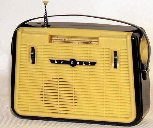
Instruments based on the radio. Modification of the receiver “VEF-Spidola”
The radio is a transistor superheterodyne (Fig.For the; scheme of the old GOST) and is designed to receive the stations in the bands long, medium and short waves. The receiver contains a mixer, separate local oscillator; three stages of the Ombudsman, the amplitude detector and uzch the complex except “spidoly” is universal prefix for testing semiconductor devices and the measurement (determination) of their basic parameters. Since the complex devices will be used in stationary conditions, power is supplied from a network source, is a separate external unit.
Of the vacant battery compartments you must remove all the valve — spring contacts and getincome plank with contacts. The wires running from the straps to unsolder. The power cord 9 (see Fig.2) going to the switch (interlocked with volume control), keep. The second end of the switch to connect one of the bottom connectors on regular round panel located on the back of the receiver. The second lower connector to connect the housing (+9). These connectors will be connected to the stab contacts from the power supply (±9 V). From connector “external speaker” to unsolder the wires to the secondary winding of the output transformer TP2. To one of the vacant connectors is provided with a voltage — 15 V from the same power supply universal consoles (along with V — 9).
Power supply
The power supply is assembled by the classical scheme and contains a network step-down transformer TR1, the diode bridge VD1 —VD4, filter capacitor C1, C2 of the regulating transistor VT1, the base voltage across the resistor R1 and the Zener diode VD5 and protection against short circuits, performed by the resistor R2, the transistor VT2 and resistor R3 (Fig.1).
As the transformer TR1 can be used the transformers of vertical sweep of the TV types TCEs or TVL or any low-power (5 — 10W) unified network transformer types TPP, TAN, TN, or any other power transformer with a voltage on the secondary winding 11 -12 V. the Diode bridge — any of the series KC or KD or four diode type D226 or old samples — D7. Filtering capacitance C1, C2 is regular. The Zener diode VD5 can be replaced by any other voltage stabilization 9. VT1 must be installed on a heat sink with an area of 50 cm2.
Resistors — MLT or sun with a power dissipation of 0.25 — 0.5 W resistor R2 — homemade from a piece of wire with high resistance — manganin, Constantan. You can use a small cut of a heating element from an old electric iron or tiles. The transistor VT1 can be replaced by KT814 KT816 or old samples П213, П216. П217, П203, П203Э, P4 (П4М, П4Э); the transistor VT2 is on П40, П41, П42, tribe-apparatus P15, R16, П116; KT315 — any low-power. The power supply is going in a plastic box of suitable size.
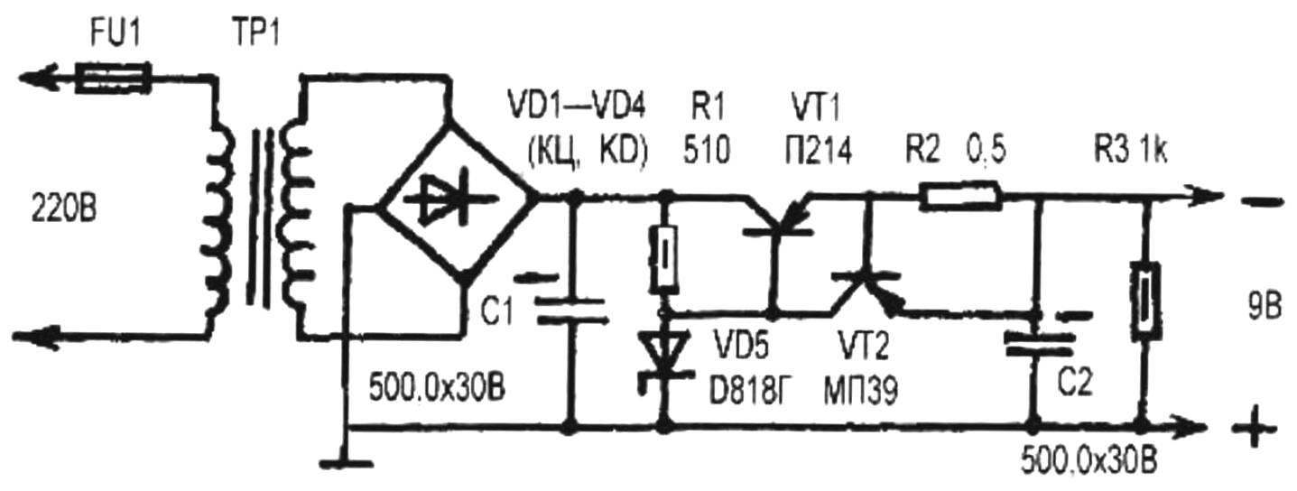
Fig.1. The power supply unit of the measuring complex
Power cable made of three wires with a length of 0.5 m each in isolation. Wire size — 0.25 — 0.5 mm2. Stab plug to connect the power cable to the complex devices are made from the contact records staff contact getincome current collectors and soldered to the cable ends. Places close ration stamps.
At the end of the Assembly of the power supply check the installation and connect the power supply to 220 V by using DC voltmeter, check for output voltages and their values —they should be in the range of 8.9 — 9.5 and 15 — 17. Test the protection — cut wire short-circuit output conductors of the power supply (±9 V). The output voltage should be almost zero. Subtract the shorting conductor — the output voltage should recover. Disconnect the power supply from the mains and close the box lid. Stab a plug inserted into the socket of the regular panel of the radio located on the back side. Soldering the wires on the regular panel are described below.
Alteration of the receiver will start processing in the HS oscillator with amplitude modulation.
Signal generator and amplitude modulator
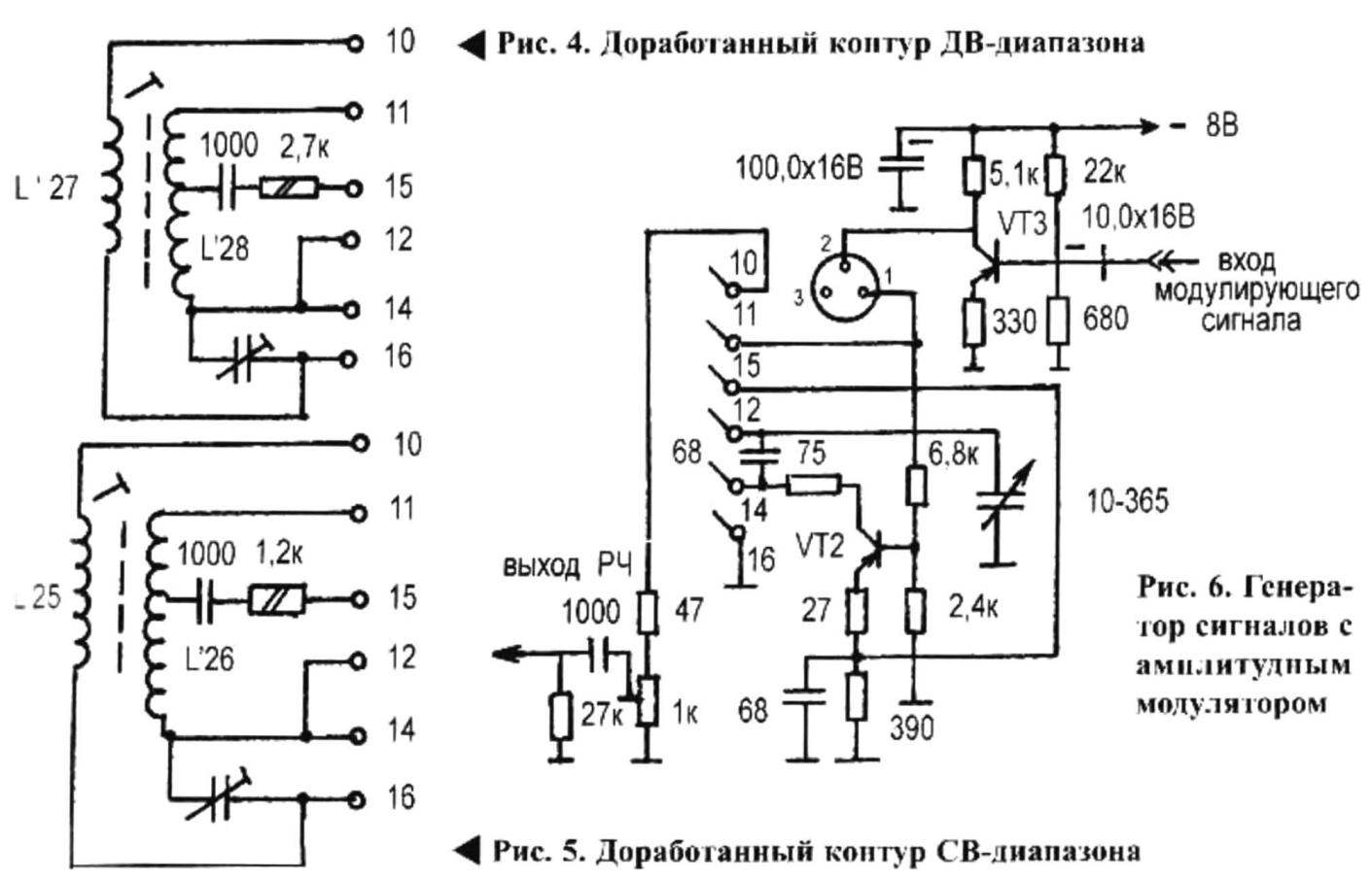
Signal generator (Fig.6) is assembled on the basis of a separate local oscillator operating on the transistor VT2 by the scheme inductive treatacne. Transistor VT3 blocking included in the circuit of the oscillator and acting as a voltage regulator, will take over the role of the amplitude modulator. The schematics of these cascades need to remove capacity of 20.0 µf from the power supply circuit of the collector VT2 and the 220 Ohm resistor.
Capacity of 0.05 microfarads in the base circuit VT2 ground, capacity 0.05 UF from the feedback circuit to exclude from the base circuit VT3 to eliminate the diode VD1, instead solder the resistor (ULM) is 0.125 to 680 Ohms In the circuit of the collector VT3 is to introduce a resistor ULM — 0,125 5.1 kOhm, power VT3 to implement bus — 8. Very the bus bridged to the unit with the capacity of 100,0×16 V. power Wire lo from the slats No. 11 range switch (AP) (slats located behind the black background of the scale plate under the drum PD) and the base end of the resistor 6, 8 ohms of the transistor VT2 is not yet connect. The connection of the collector of VT3 with a capacity of 0.05 UF base of the VT2 transistor and a capacitance of 0.05 µf feedback removed.
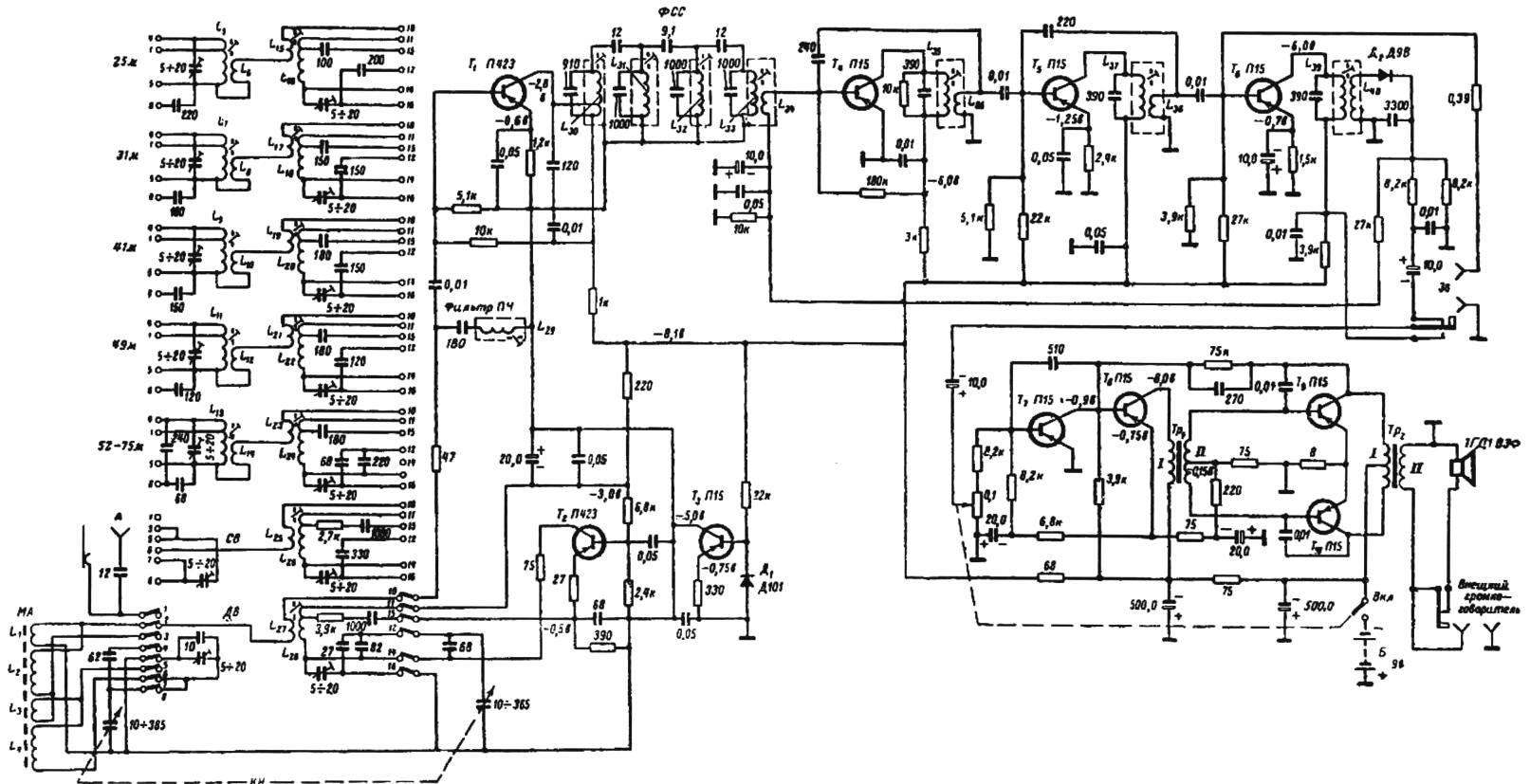
Fig. 2. Schematic diagram of the receiver “Spidola” (the image of the old GOST)
Track on the PCB going to the collector of VT3 behind the branch cut. Keep grounding the emitter of the cell (capacitor 0.05 UF and a resistor of 1.2 kOhm) transistor VT1 (see Fig.2). The transistor VT3 to solder the capacitor 10,0×16 “minus” to the database. Capacitor 180 pF of the if filter (L29) to remove. The connection of the resistor 47 Ohms and a capacitor of 0.01 µf base /T1 alienate.
On bars DD need to perform the following operations related to the restructuring of the circuits of local oscillator and RF output voltage. In the local oscillator band frequency of the oscillation higher than the frequency of the received signal at 465 kHz (FC). In this regard, the use of scale radio when installing a frequency generator and configure any radio receivers within normal ranges impossible. It is therefore necessary to reduce the frequency of all circuits of the local oscillator to 465 kHz.
Indicated on the diagram (Fig.2) turn trimmer capacitors 5 — 20 PF on many models is replaced by a constant capacitance in the range of 9.1 — 15 PF. These containers with all planks of PD need to be removed and installed in their designated sockets trimmer capacitance type KPK-MN for surface mounting, which will be made to adjust the ranges of the generator. However, to rebuild the oscillator frequency through these capacitors is possible only in the HF. At these ranges the ratio of the frequency FD to the frequency of the generated oscillations is approximately 3.8% at 25-m range of up to 10% on the 75-m range. On LW and MW bands lo frequency above the desired:
((150+465)/150 kHz = 4 to (1600+465)/1600 kHz = 1.22 times).
To reduce the frequency of these ranges, you must rebuild and coil circuits. For reshaping the contours of DV and SV ranges it is necessary to increase the inductance of the circuits. In the LW-range this is achieved by winding a greater number of turns of the coil circuit. Regular winding coil is completely removed. The new winding consists of 50+450 turns of wire PEV-2. Diameter of 0.09 and 0.12, the connection coil 50 turns of the same wire (diameter 0.2 mm), the resistor in the feedback circuit (OS) is replaced by ULM-0,125 2.7 kω, the circuit capacitance 82 pF is removed and instead put the jumper. The end of the new coil (127), previously running on contact No. 2 strap PD is soldered to terminal No. 16 (housing). After completion of the contour DV-band has the form (Fig.4).
In the range SV with the contour of the coil winding is also removed completely. New winding has 20+135 turns of wire sew-2 diameter of 0.09 — 0.12 mm, connection coil — 15 turns of wire sew-2 with a diameter of 0.2 mm, the resistor is replaced by OS ULM-0,125 1.2 kOhm, 330 PF capacitor removed and the contacts 12 and 14 are connected by jumper straps the end of the new winding connection 1.25 soldered to terminal No. 16 (housing). Circuit diagram of the SV-range is shown in figure 5.
The HF 25,31,41,49, 52 — 75 m. In these ranges, the contours remain almost unchanged. In addition to the installation setup of the capacitors, it is necessary (on all straps KV) to the grounded ends of the coils connection, L15, L17, L19, L21, L23 — unsolder from pin No. 9 and solder to the pins No. 16.
For switching the freed ends of the coils connection L6, L8, L10, L12 and L14 connected to pins No. 9 on bars of the drum PD, it is necessary to install additional lamella under that contact (in the performance of normal radio is missing). For this you need to remove the black plate in front of which moves a reticle scale. Under the contact No. 9 of the straps on the plastic fittings need to have a groove depth of 1 — 1.5 mm triangular needle file (type “dovetail”). From the old Electromechanical relays of the RES series pick up spring contact length of 33 — 35mm and a width of 4 mm and bend it so that the rotation of the drum strap with contacts smoothly “ran” at him. Insert (tightly) the slat in the groove and a hot soldering iron using a razor blade, heat the plastic — it should be slightly melted and firmly to strengthen the slat in the valve. Connect the slats, and slat # 2 and 6 DV and SV ranges will be discussed below. Adjusting the output voltage of the RF of GS is carried out smoothly with the help of variable resistor 1 kOhm, which should be placed in the vacated upper-left compartment (when viewed from the side of the PCB). The potentiometer may be of any type from series SP, but not the wire.
On average, the left compartment over the formed round hole socket is installed to output the RF signal connected to the engine control level of the RF signal through the capacitance of 1000 pF the Socket is grounded to the housing through the resistor 27 kOhm
In the lower left compartment bring the hole up to a diameter of 15.5 and insert a three – or five-pole connector from the VCR (TV). Drill two holes at the ends with a diameter of 3.1 and with the help of screws and nuts M3, fix the connector on the valve behind the ears. Lamel No. 11 and the end of the VT2 base resistor of 6.8 kω connect to the leg No. 1 of the connector to the leg No. 2 solder the wire and connect it to the collector of VT3 blocking. The output socket of the TOS, connect with resistor 47 Ohm cut thin cable RK. The shield connect with the body nearest to the resistor 47 Ohm grounded track. Next to the output socket to the braided cable, solder the resistor 27 ohms.
About setting and the basic characteristics of the HS will be discussed in following publications.
R. HAKOBYAN
(To be continued)
Recommend to read
 THE PERFECT CASTLE
Many people know or realize that any lock, even the most expensive, it is possible to open, having certain skills and tools. Design offer of the castle is simple, but will provide a...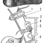 BRAKE light FOR BICYCLE
Agree to see ka road in the evening time the cyclist is not easy, even if the two-wheeled machine and is equipped with reflectors-reflectors. Especially fraught with danger moments...
